Graupner’s Almost-Ready-To-Run Smit Rotterdam – reviewed by Terry Small.
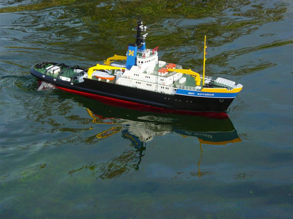
Announced and on full display at the 2006 Nurnberg Toy Fair was a completed 1:76 scale model of the well known tug Smit Rotterdam, launched under the Graupner Premium line product range, part number 2006. This and other future models are to be based on a series of particularly high quality ready-made models incorporating an unprecedented level of detailing and just requiring radio and batteries to complete. The core of this high quality model is the robust moulded grp hull, complemented by a strong superstructure and deck constructed from laser-cut ABS parts. Many of the small items are constructed from metal and almost everything is factory assembled by hand or machine. All has been spray finished using semi-mat paints, including all decals applied. The many details and scale fittings give the boat an impressive scale appearance on or off the water.
Article continues below…
Enjoy more Model Boats Magazine reading in the monthly magazine. Click here to subscribe & save. The large deck openings assist in an easy installation of the radio control components, and the procedure is quickly completed. To prepare the boat for running all you have to do is install the R/C components and the drive battery, carry out a little soldering, and the model is ready for the water. But is it really! Model Specification BackgroundSmit International, sometimes just referred to as Smit, has a proud tradition of nearly 165 years of service to maritime shipping, earning themselves an excellent reputation in salvage rescues, harbour towage, transport and heavy lift, all by combining expertise and experience from around the world, and calling upon the highest quality of materials and equipment to complete the job under the highest standards – not forgetting safety and the protection to the environment. Smit Rotterdam and her sister ship Smit London, were built in 1975 to Lloyds 100A1 tug ice class 3; Smit Singapore was built in 1984 to almost the same specification as regards engine power. Propulsion is provided by two Stork-Werkspoor TM410 turbocharged four stoke, single acting, unidirectional diesel engines producing 22,000 ihp each, driving a four-bladed variable pitch propeller turning within a fixed nozzle. This gives the boat tremendous power and manoeuvrability combined with two rudders and a 650hp bow thruster, plus a top speed of 16.5 knots. The wheelhouse is situated amidships, Giving the crew an excellent viewpoint over the deck and afterdeck. It has two main towing winches, each consisting of one storage drum and two friction drums, all electrically powered. The steel towing cable is some 1,400 mtrs long by 74 mm diameter, ready and waiting for instant use, and it can pull 80 tons at 15 m/min. Their own powerful anchor handling winch is capable of pulling around 100 tons at 6 m/min. There are two other tugs, Smit New York and Smit Houston; these share the same general build shape and size with a very similar equipment specification – the one exception is the all important engine rating of 16.000 ihp, nevertheless still very powerful tugs.
|
|
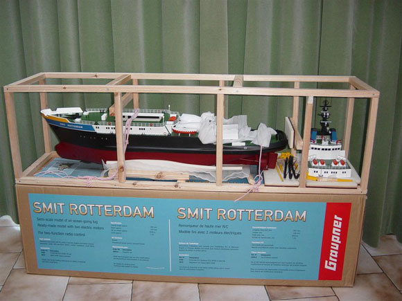
Pic 3: Very substantial packaging protects the model. Pic 4 & 5: More examples of the protective packaging – note the excellent paint finish. Assembly startsThe first job is to carefully unpack the model from what must be said is some excellent packing by the manufacturers – you even get a very nicely made wooden boat stand with the tug’s name on it – always a good start whether a kit or a pre-built. As stated there is some assembly work involved along with fitting the radio gear and batteries, following the outlined specification given. The basic equipment required to get the model on the water is a 2-channel radio set, either 27 or 40 MHz, one fully proportional speed controller, minimum 20 amps rating, and possibly an extension lead for the rudder servo, good quality connecting wire, connectors for the main power and two 6 Volt 10 Ahr lead acid dryfit batteries – oh, and not forgetting the all important associated charging setup. Graupner have chosen well in their method of packing the model for long journey’s – externally it looks like any normal large box containing a model boat kit, but once open you are confronted with a very sturdy wooden framework to which the model is well anchored with the use of ‘elasticated rope’. This is in addition to being secured down at two points with extra wooden plates. It’s a case of gently cutting each cord with a pair of light weight cutters or scissors, making sure the elastic cord does not spring back and damage anything, and once all have been cut and plates unscrewed the hull can then be gently slid out. The superstructure plus the three lifting arm cranes, tow bows, cable guards and deck house, are strapped down separately using similar cord. On removing each part the high quality of the build and components used is very noticeable, enhanced by the very good quality paint finish. Good access to the inside of the hull has been well thought out; the rear hatch cover is held in position by two plastic clips underside which once removed reveals a well for the location of the rudder servo – big enough for a standard servo. First thing is to set the servo position to centre with the use of the transmitter, then to fit the servo simply drill four small but not to deep pilot holes as per the position of the mounting lugs on the servo, then with the normal mounting kits supplied with the servo screws and rubber shock grommets, secure the servo. The servo control horn requires drilling out to accept the supplied pre-bent control rod; this is secured to the horn with the use of twisted solid wire as per instructions. Once fitted make sure on executing right and left turn both rudders give the same amount of movement and maximum throw, also check that nothing can foul the deck or underside of the deck hatch. If this should happen, bend the rudder arm downwards, carefully. Do remove the arm from the rudder plate and servo first, and then carefully bend it. Wiring Up StageFirst make sure when carrying out any wiring you keep all polarities the same and terminated in the correct place on to the controllers, etc., otherwise you will melt or blow something up and that means expense. Graupner’s instructions are very clear in their method of wiring and connectors to use although they do not indicate if the two 6 Volt batteries stay as 6 Volt per motor or are wired in series to give 12 Volts operation to both motors and controllers. I have changed the parameters slightly by introducing two speed controllers which will run on a 6 Volt system (one battery per speed controller) and a separate receiver battery. This is because I do like full independent control of both motors so I have chosen to use two superb performing speed controllers from ACTion – these being Condor 20/2 Autoset Speed Controllers. I have used these in the past with excellent control results, well suited to this type of model and motor. They are available to purchase as kits which require making up as per ACTion’s very clear and concise instructions as long as one has good practical soldering skills – however if this is not the case, then they are available ready built at a slight extra cost and there is no setting up required – you just connect them up and use. For the layout I decided to place both speed controllers as low down as possible at the bow end in front of the main drive battery position, mounted on Velcro for easy fitting and removal. I decided the batteries would fit into a fixed tray in the bottom of the hull. the tray was made out of styrene plastic and fixed permanently with glue once I had finalised the ballasting/trim of the model. This makes for easy removal of the batteries for charging and lighter transportation. Also, the last thing you want whilst sailing is for the batteries to move around hence the tray. Packing material-like foam would do but not for me. All connectors used were of the Amp type, not Tamiya as stated, but only because that’s what I had available at the time. The connecting wires for power are colour coded and correctly current rated for the job – I use Automotive twin multi-stranded flexible red and black wire available from good car spares shops. All wire connectors are crimped and also soldered to be double sure of a good solid connection. I always try to lay the wires out as tidy as possible which helps in reducing any RF noise. It’s also good to see that Graupner have pre-fitted motor suppression capacitors to each motor to eliminate any airborne high frequency noise that could effect the radio signal. The wiring instructions supplied show both motors to be wired in parallel to one speed controller operating from a 2-channel radio set and a standard 4-cell receiver NiCad pack, with the main motor power source as two 6 Volt 10 Ahr dryfit lead acid batteries (these can be purchased from model shops or Maplin stores). Also note one motor will be wired the opposite to the other as they need to be contra-rotating – or you could/reverse the function of the transmitter control stick for that channel if available.
|
|
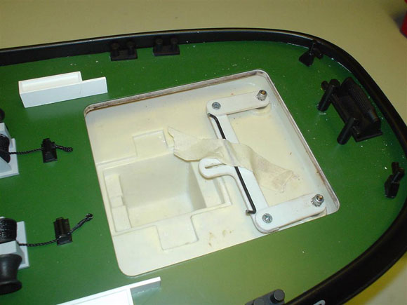
Pic 6: Well for the rudder servo. Pic 7: Rudder servo installed and connected up. Pic 8: Fitting the pre-bent control rod to the rudder servo. Pic 7: Rudder servo installed and connected up. Pic 9: Motors installation – see notes in text concerning the coupling screws and motor alignment. Pic 10: Cheesehead screws replace the original coupling screws. See text for details. Pic 12: The two ACTion speed controllers are positioned. Pic 13: The batteries are installed in the tray. Pic 14: Underside of the superstructure. BallastingThe position for the batteries is as shown and it should be borne in mind at this stage that the two drive batteries are the main ballast – in fact the only ballast required, so their final position can only be set once all is complete with all fittings and superstructure in place. The best place to carry out this operation is, yes, the bath. Ignore the politics that this might cause. Drive line checkAnyway, before that it’s a good idea to check that the propellers and shaft couplings are positive and tight, as they may have come loose in transit; re-tighten them if necessary with a very small sharp flat-bladed screwdriver. This was the first problem I encountered as both couplings and screws were not tight on both the motor and drive shaft, and not made easy to tighten due to the fact that some sort of glue or sealing wax covered the screw heads. After much sweat and toil plus a few cross words, the screws in the couplings were got at and removed and standard small cheese head screws with the same thread were fitted which, with their better screw head, makes for better maintenance and a much easier life in the future. These were then ‘locked’ in place using Tamiya Thread Lock or even easier, nail varnish can be used. I do use this in the workshop from time to time as an ideal sealer/lock (what must you be thinking my dears!?) This is placed on the thread part only as it is being done up – not the screw head. I also decided to check for motor alignment as if this is incorrect it will increase current consumption/power from the batteries, thus reducing on-the-water running time – and was I right in doing it as one motor pulled over 3 Amps and the other kept binding up, mainly due to the motors being too low within the mounting saddles at the wire end of the casing. Also the motor aluminum retaining strap was screwed down too tightly – in fact I actually found it to be placed too far forward, so after some readjustment and a little cardboard packing between motor casing and saddle whilst checking the motor current being drawn with an in-line Ammeter, I managed to decreased the current being drawn to 1.85 Amps, a considerable reduction. It also gave a marked reduction in noise. Well worth a couple of hours work. It’s also worth noting that Graupner have fitted oil tubes to both shafts, so a few drops of ‘3 in1’ oil was applied. On further investigation the motors are 540 3-pole type, made by MAKA whoever they are. Admittedly there are better alternatives but as these are supplied why not use them.
|
|
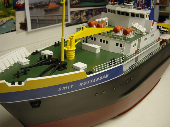
Pic 15: Almost complete. Pic 20: Ready for the water. One or two other pointsI would advise that the following text within the supplied instructions should not be carried out – quote ‘if the coupling hose slips on the shaft end, remove the coupling and clean it carefully, then glue the hose to the end of the shaft using a drop of Superglue gel or liquid’. This is not a wise move! The connecting wires to the drive battery terminals need to be terminated in the correct type connector push-on automotive spade type. All solder joints if made should be insulated with pieces of heat-shrink tubing which makes for a neater finish – alternatively insulating tape can be used. Next it’s just a matter of connecting all leads up to the receiver. The aerial wire was secured around the underside of the deck superstructure opening with the use of tape which is my normal way of fitting aerial wires. It should be said that this method only has a very slight adverse effect on the radio signal received and I have never had any problems so far. The other alternative is to make up a vertical aerial (whip aerial) from thin wire that can in some way be secured to the top of the deck. If you do this you must shorten the flexible receiver aerial wire by the same length as the whip, as the receiver is tuned to a certain length of wire. Placement of fittingsThis part is the easiest to action – you just need to look at the colour box pictures. The main mast is simply placed into the pre-drilled hole on the bow deck, adding a little Superglue gel for a permanent fix and making sure it is at the right angle – just hold still and wait for the glue to work. The rear deck house just gently slides over the coaming then the tow bows or guard rails push-locate in position by a locating pin and hole in the stern deck. Two of the tow bows are the same with three ‘ A‘ frame legs – these go directly after the deck house, working to the stern. The other one is different with two ‘A’ frames – this is the stern or end one. Do not glue it in position for access reasons. The three cranes just sit over three mounting lugs – once again do not glue. Final ballasting and checkAs stated earlier this is best carried out in the household bath. The main ballast for this model is the two 6 Volt lead acid drive batteries which are easily placed inside the model at the bottom of the hull via the superstructure hatch. These then sit upright side by side in my made up tray, requiring some adjustment from bow to stern to achieve the correct working trim. The only way to do this is to keep removing and replacing the superstructure and adjusting the battery tray a little at a time, then checking all around at the hull waterline until the trim is correct. Remove the superstructure, draw around the tray marking its final location, then remove all and glue the tray in as marked. As I also said earlier, packing foam can be placed in and around the batteries to wedge them in place to try and prevent any movement. But they are heavy and may move around. My way is just slot the batteries into the tray, connect up and away you go with constant trim. With all connections made a radio range check was carried out, a check that everything moved freely and in the right direction, and that the propellers contra-rotated in the right direction for forward and reverse movement – and she was ready for the water.
|
|
On the waterAlthough after many years of making and running models the very first launch is always the most nervous – just like actors or performers before going on stage. You know what should happen and expect that it will. The best advice is no matter whether it be a pond, lake or small river, always keep near to the bank at first, then as one’s confidence and trust begins to build, venture out a bit at a time, making sure no floating weed or debris is around. Power from both supplied motors and brass props was excellent with the added bonus of ACTion’s reliable speed controllers both at high and low revs. The turning circle was very positive with same direction power and rudder movement. If one motor is in full reverse and the other full forward, and with no rudder applied, the model turns in its own length, and of course even quicker if full rudder is applied. On going full forward turning looked very realistic, including the wake, and even steering astern is positive – so 10 out of 10 for manoeuvrability and power. As for time on the water, from a full charge I obtained 28 minutes, which all depends on how good the batteries are and how you control the model. In my case it should increase as I did put it through its paces a bit. Other thoughtsIf controlling both motors with two separate transmitter sticks is too much then I would advise the use of a motor mixer, which our friends at ACTion produce – the P40C Autoset is the kit version and price is around £16.00. This allows differential speed control of twin motors in conjunction with the steering/rudder position – in other words it will slow one motor and speed up the other, which when turning gives a more positive and controllable tighter turn. I can confirm it does what it states extremely well as I have now installed one in the Rotterdam. Contact ACTion electronic kits on 01767 681564 or see the their full range at www.actionkit.co.uk or email craig@action.co.uk. If you, like me, intend to add some figures then I would suggest Preiser 1:72 scale figure sets 72406 and 72409 from On Tracks ConclusionGraupner started the trend of good quality RTR models with their Southampton Tug, which I reviewed a while ago and came to the conclusion that it would be hard for any manufacturer to better. Well little did I know that Graupner were to do it themselves. The Smit Rotterdam, in my opinion, is a very suitable subject to produce as a RTR model; the scale and size make it a very easy model to transport with very little work to do to get it to the water. Billing Boats were the first to produce a full kit of this boat at a very similar scale some years ago – however it was all in wood including the hull and did contain a little more added detail, and would take many hours of top quality workmanship to get it anywhere near to the finish that Graupner has achieved as an almost ready-to-run boat straight out of the box. The down side is the price. At around £600 plus it is certainly not cheap, but if you consider how many hours it would have taken to build, perhaps not that bad a price really. It’s a very high quality and clean built model that lacks little details here and there like handrails down the stairs, ladders, handles and hinges on the doors, and even to handrails on the superstructure – all of which can be added as extra detail by the modeller with not enough time to build it all from the keel upwards, but does have the time add bits and bobs – better still his or her own touches. At the end of the day it is expensive but you are getting a quality model to be proud to use and display and if you look after it should hold its price too. And as this one is launched another RTR model from Graupner is to be coming down the slipway soon, this time a WW2 German Navy heavy warship cruiser, Prinz Eugen. At some 1470 mm long this promises to be some model that will include many detail features like aircraft, guns rigging and wood planked deck. Details regards these and other models at very good prices are available from A Model World, Tel: 01606 76513 – or see their excellent website www.amodelworld.co.uk. Graupner’s web site is also very informative, especially the English text version at Graupner. First published in Model Boats Issue 5, May 2007 |