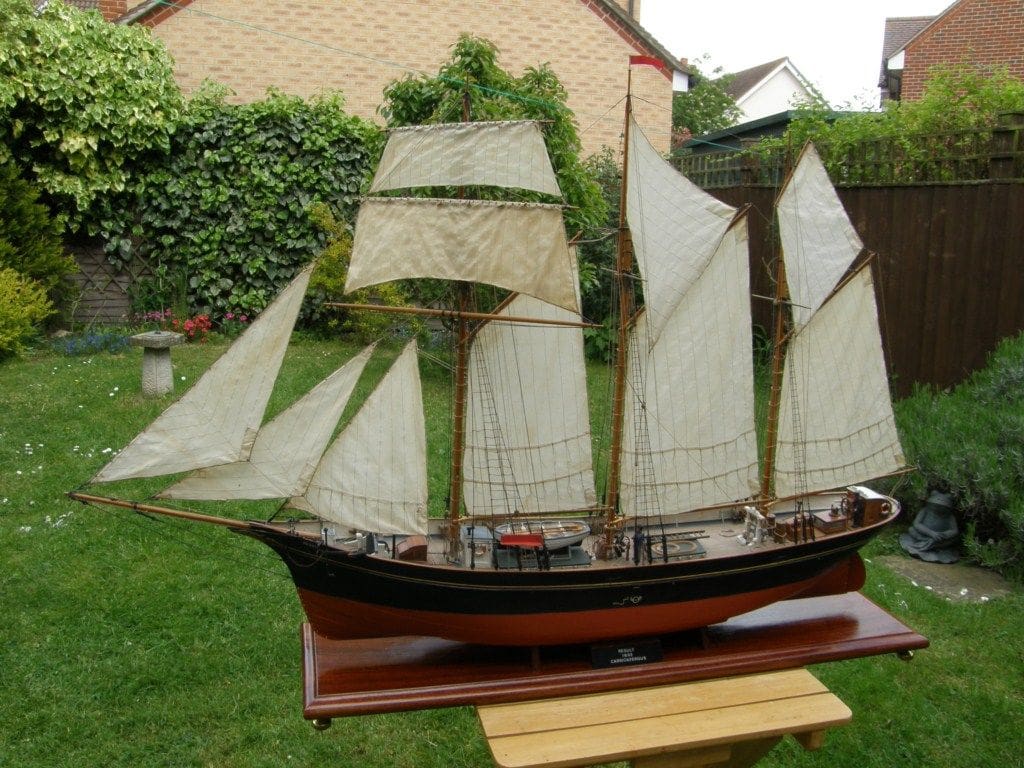
The Reverend PETER SPENCER describes his scratch built topsail schooner
Brief History
The topsail schooner Result was built of steel at Carrickfergus, Northern Ireland, between 1892 and 1893. She was designed to sail quickly and turned out to be one of the fastest and most successful schooners ever to sail in British waters. Her registered dimensions were: Length, 102.0ft; Beam, 21.7ft; Draught, 9.1ft.
Enjoy more Model Boats Magazine reading in the monthly magazine.
Click here to subscribe & save.
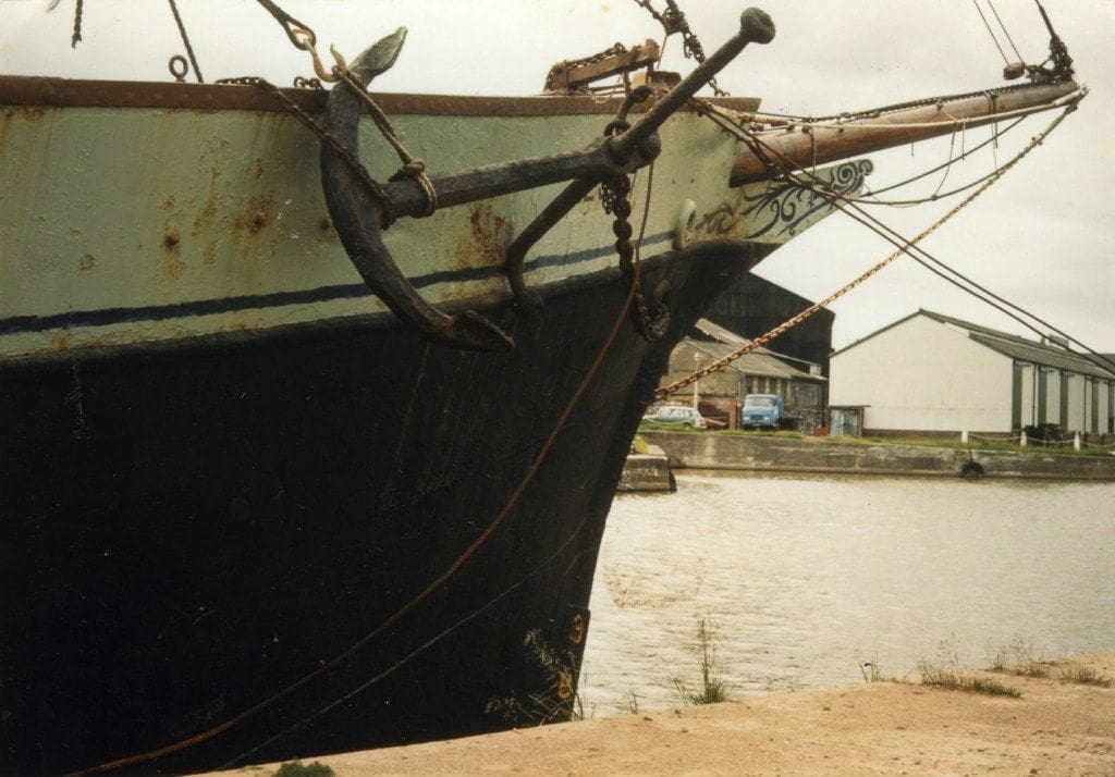
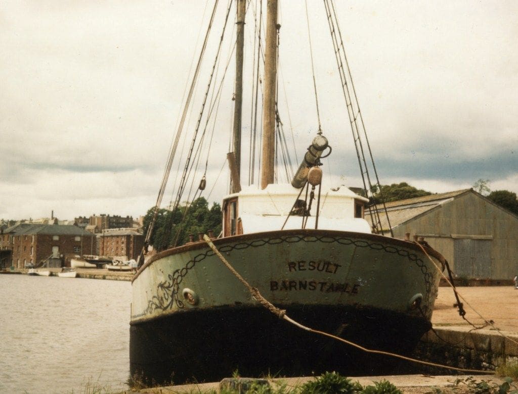
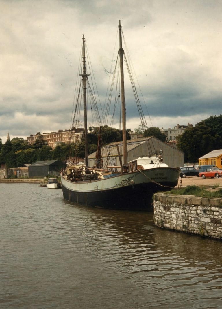
During World War Two, Result was requisitioned by the Admiralty. In later years her rig was reduced and she was converted to a motor-ship, and was based at Barnstaple. Photos 1 to 3 (I am sorry about the quality) show her in harbour at Exeter around that time. In 1970, in a very battered state, she was purchased by the Ulster Folk and Transport Museum to be restored back to a schooner and to be exhibited on land. She was subsequentially transported from Belfast to the Cultra site in 1979 and her importance is signified by being listed in the UK Historic Ship Register of Core Collection Vessels. The National Museums of Northern Ireland, website: www.nmni.com, have a link to the Ulster Folk and Transport Museum and what it possesses.
When first built, Result was a beautiful ship with a lovely sheer, which is why I wanted to build a model of her. Another reason was that with her fairly large rudder and bilge keels, I thought a model was likely to sail well without resorting to a false keel and an out-of-scale rudder.
I used plans drawn by David MacGregor (published in The Merchant Schooners by Basil Greenhill, 1951), scaling them up to 3/8 inch equals one foot. The Ulster Folk and Transport Museum supplied some very useful photographs of the ship out of water showing the run of her plating and the position of her bilge keels.
The model
This is not a ‘blow by blow’ account of its construction as the model was built more than 15 years ago. Consequentially, few step-by-step constructional pictures exist, but I hope the following notes will provide some inspiration to readers of this magazine to have a go at something a bit different and of the ‘scale sail’ variety.
Materials
These were rather an odd assortment, consisting of a vandalised garden seat with teak slats, a discarded spruce mast, mahogany rudder and copper buoyancy tank salvaged from a derelict clinker-built dinghy and various other bits and pieces. In other words, most materials were re-cycled.
The hull
The hull was built out of teak from the garden seat with the frames formed by steaming and bending over plywood moulds. Initially, the stem, keel and sternpost were assembled and placed in position, after which the shaped frames were glued into position with Araldite epoxy adhesive. The stern was built-up from solid wood to act as a convenient foundation in that difficult to plank area. What was to be unusual were the sheet copper bulwarks. Remember this was a model of steel hulled vessel, therefore sheet metal for the bulwarks was not inappropriate.
The planking was straightforward, but the copper bulwarks and stem were rather more difficult to accomplish. A very powerful soldering iron managed to overcome the rapid loss of heat caused by the conductivity of the copper. With the hull removed from the building board, the copper was cut into sections and glued, screwed and soldered in place, with holes cut for the freeing ports as necessary. A narrow strip of copper was soldered to the inside of the bulwarks and stern to support the main capping rail.
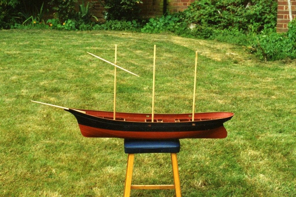
Photo 4 shows the hull planked and with the copper bulwark screwed to starboard side. The fully completed hull, ready for deck planks to be laid, is shown in Photo 5. I apologise once again for the lack of constructional photographs as this model was constructed some years’ ago, before I decided to put pen to paper, but I hope they give you some idea of what was involved.
Shell plating
The shell plating for the hull was represented with strips of Bristol Board above the waterline and below by thin wooden strips with car body filler between them to cover spaces. The use of Bristol Board proved to be a mistake, since if the edges lift at all or become exposed, water can get into and underneath it, causing swelling and leaks and disintegration of the material. Fortunately, this has seldom happened thus far, but has not been repeated since! The rivet heads on the shell plating were simply represented by small spots of glue. Tedious to apply, but once the correct ‘blob’ size was determined, it was just a matter of getting on with it.
The rudder
This, seen on the finished model in Photo 6, was made from sheet brass with plastic (styrene) sheet added to each side to bring it up to the correct thickness. It was given two brass bearings, one at the top of the rudder and the other at the bottom, the remainder being dummies. A brass tiller arm on the top of the rudder post inside the hull was connected to a brass rod and in turn joined to a servo output arm.
Radio control and winch mechanism
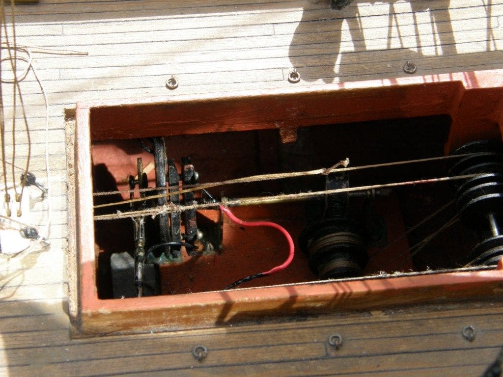
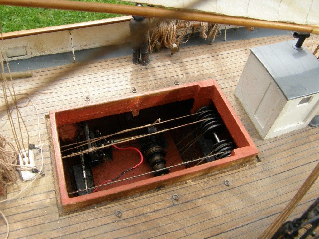
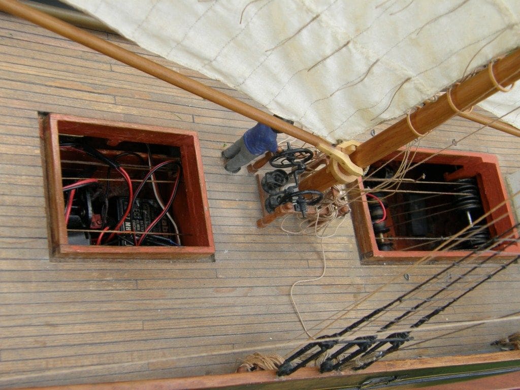
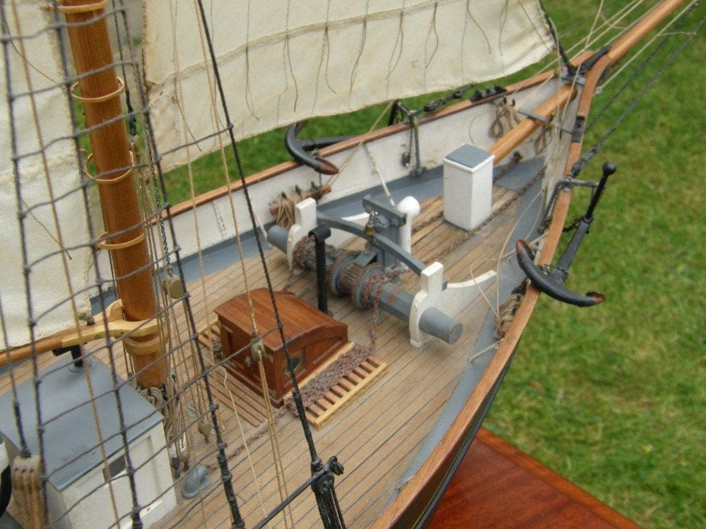
The model is equipped with just a two-channel radio system. To enable this to operate the sails, I adapted a design by Alastair Brown in which one of the main features for switching on and off the winch is a brass plate with a non-conductive strip down the centre, Photo 7. This is rotated back and forth by the servo, making and breaking electrical contact. Wires then lead to the motor which drives the winch. This has three drums with lines, leading fore and aft over pulleys, connected to the various sheets and the braces of the lowest of the yards, Photos 8 and 9. Thus, the sails on a particular mast move as one.
Deck planking
Spruce was chosen for its lightness, the planks being made with a small plane and glued to the deck beams and to one another, with black paper representing caulking. Result actually had cement waterways, so probably a bit risky to follow exactly the example of the full size vessel!
Deck fittings and crew
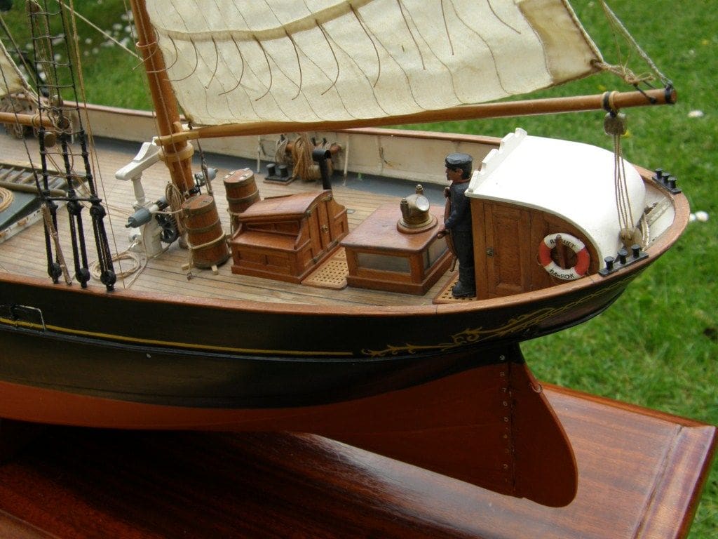
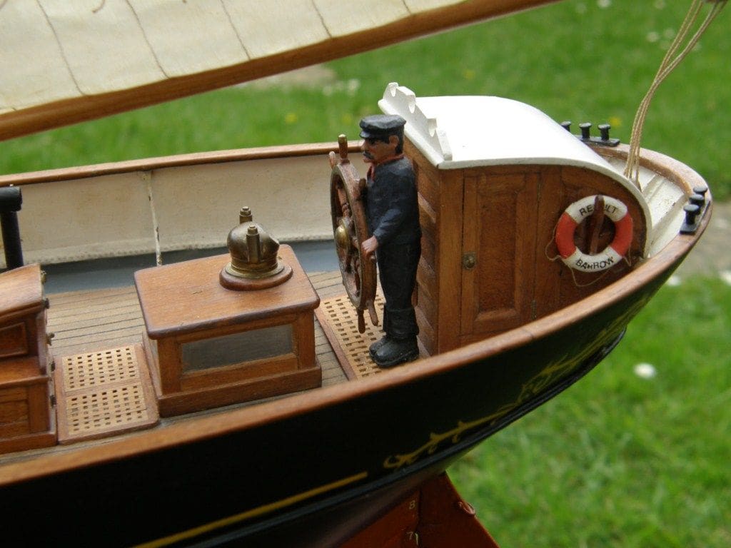
The steering wheel, Photo 10, was constructed in the same way as the real item, in wood and with detail fittings from brass sheet. The strips of brass round the rim, both back and front, were annealed before bending.
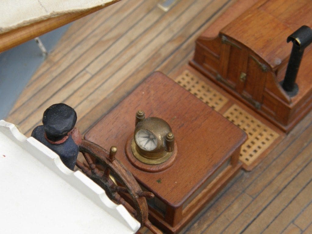
The binnacle, Photo 11, was turned on a small lathe from brass and hollowed out with a burr. Its lamps were turned separately on the lathe and soldered in place.
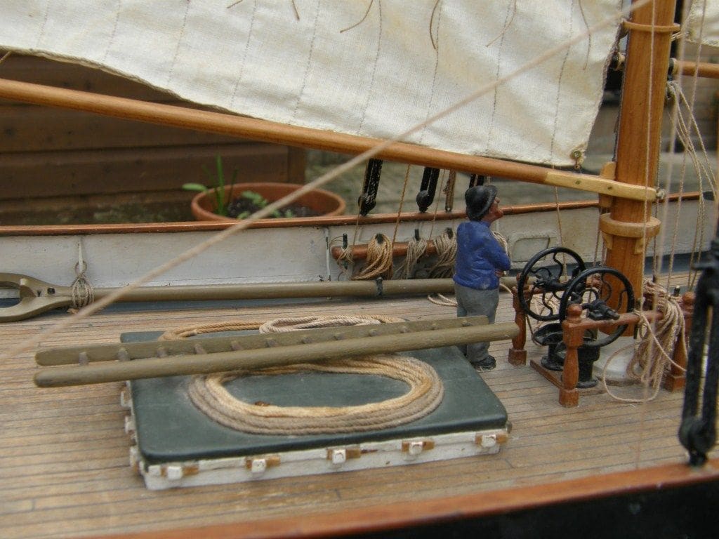
The hand pumps just behind the mast, Photo 12, were made from copper, brass and plastic.
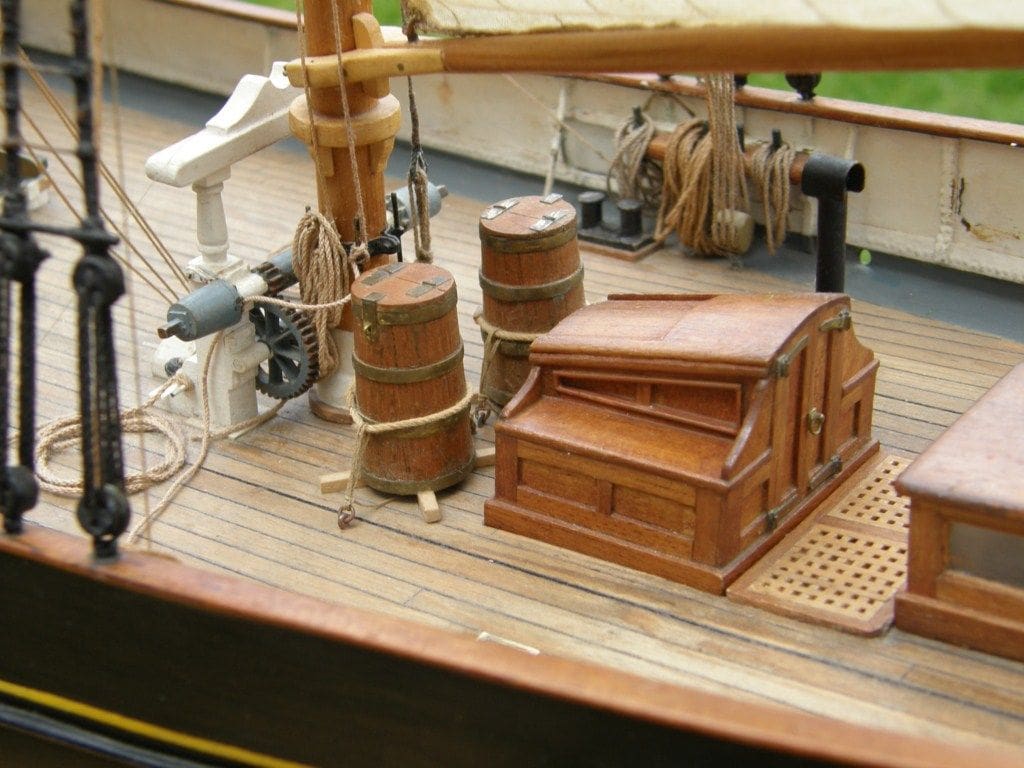
The after hatch was built up from mahogany, while the two large water storage butts were planked from mahogany with brass fittings, Photo 13. Various companionways and skylights were also built up from mahogany with their windows from clear plastic that was lightly sanded to give a ‘frosted’ appearance.
The windlass was built from wood with the pawl and ratchet gear made from plastic, Photo 14.
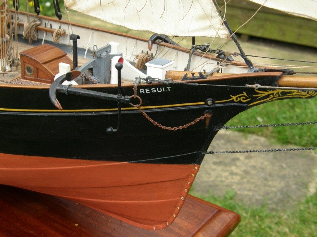
The stud-linked anchor chain was formed from short lengths of copper wire, each link having its joints soldered together once in place. Photo 15, is of the starboard anchor and the stud-linked chain can just be seen. The bending of each link was done with a small pair of half-round pliers.
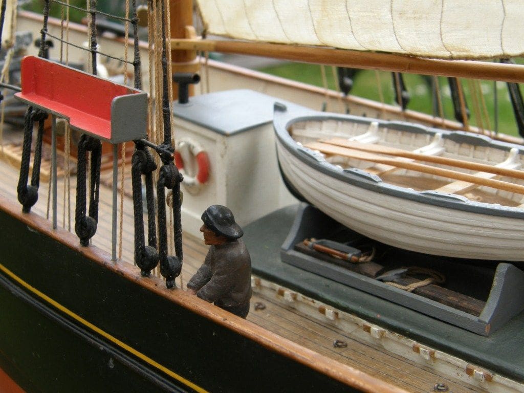
The anchors were carved from lime and fitted with brass stocks and likewise, the crew were also carved from blocks of lime.
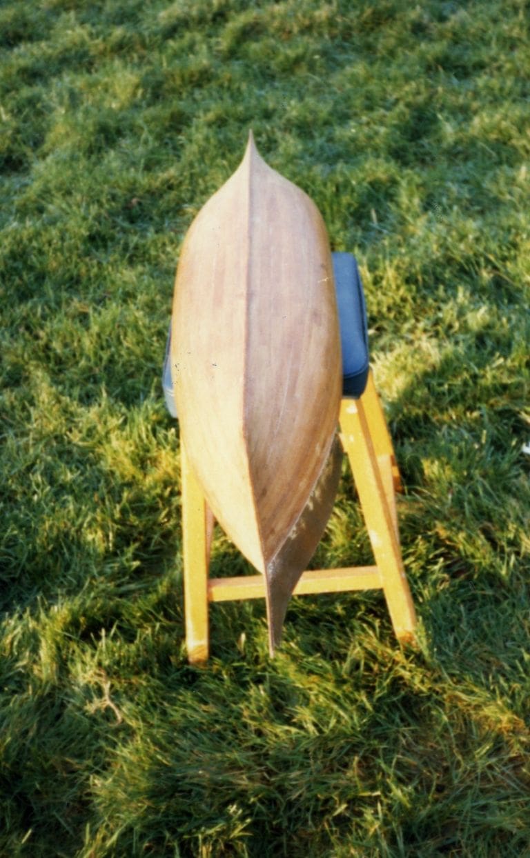
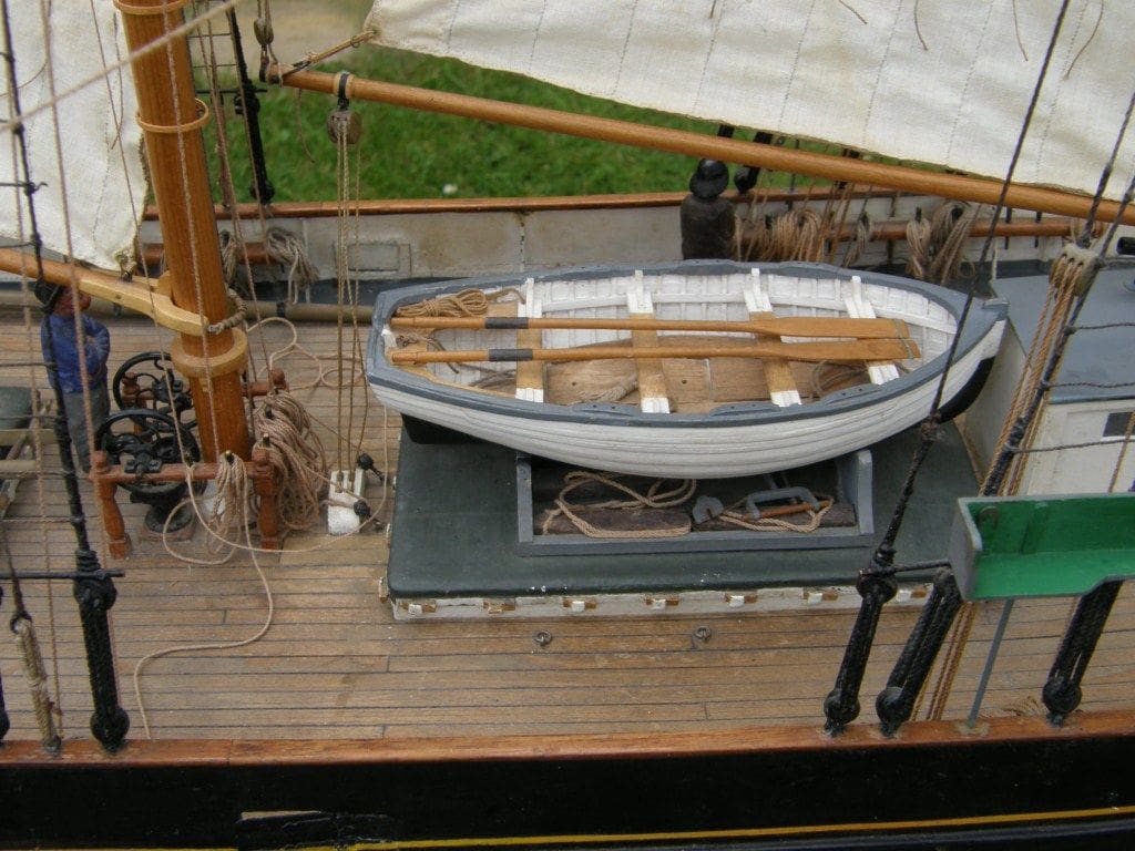
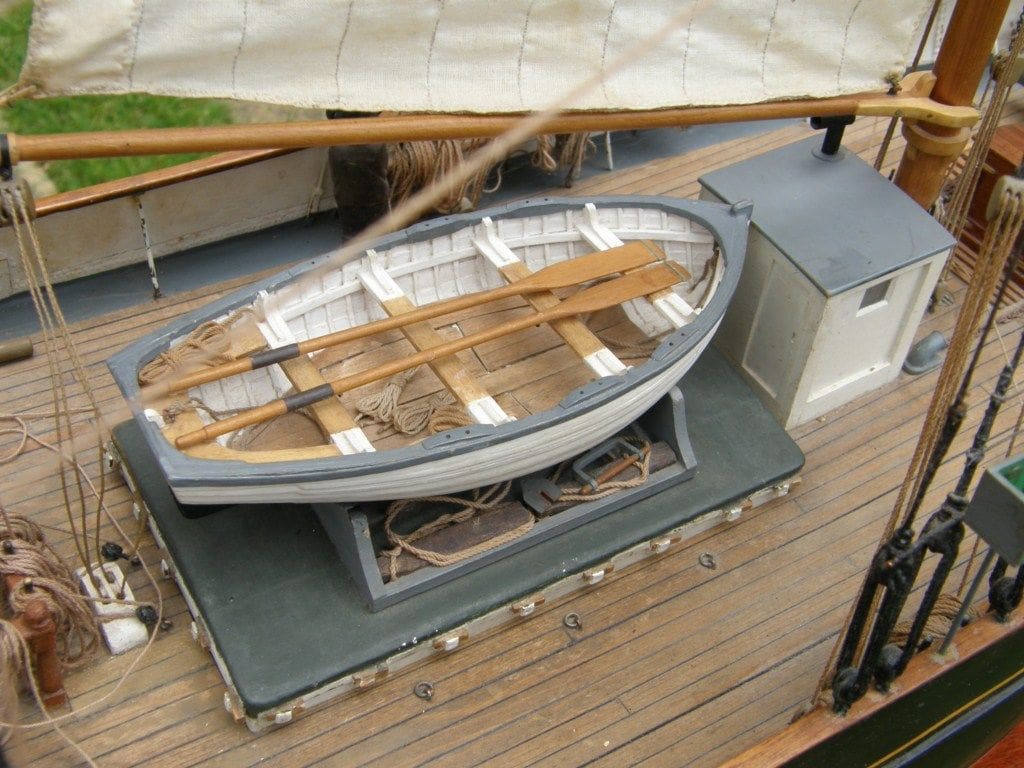
Ship’s boat
Photos 16 and 17, show this quite well. It was built from lime, the hull being carved into a very thin shell, and then the two halves were glued to the transom, keel and stem. This shell was then planked both inside and out with Bristol Board, to give the appearance of a single planked hull. For this ‘mini-model’, I used a plan of a smack’s boat obtained from the Science Museum, London.
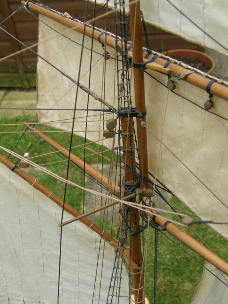
Mast, spars and rigging
Harold Underhill’s books were (and are) a valuable source of information as to fittings and other details for these types of vessel which the plan did not give. Masts and spars were as is usual built from carefully shaped dowel and the deadeyes were made from a length of wood turned on a lathe, Photo 18. Once the manufacturing process was established, it didn’t take too much time to produce enough of these, plus a few extras.
The cord for the rigging I made on my own rope making machine. From time to time at model shows there are demonstrations of this. It is great fun and you will end up with exactly what you want rather than a compromise which can be the case with commercial cord.
The rigging blocks were cast using Araldite in moulds that were made from an impression material widely used by dentists and called Vinylpolysiloxane. The moulds were made using master copies of the blocks made from wood. Here, only one of each type had to be manufactured as copies could then be produced almost ad-infinitum from Araldite adhesive, which because it is slow setting (and weight is not a problem on this model) will fill a mould completely without air bubbles and set very hard.
Sails
A ladies’ cotton nightdress provided the material for these. They were sewn by hand, the seams being represented with fine stitching in grey Sylko. Bolt ropes were sewn on with invisible thread. The sails were dyed with weak tea to give a used and worn appearance, Photo 19.
Ballast
Nothing complicated here, as this just consists of cast lead blocks and lead sheet distributed evenly around the hull as low as possible.
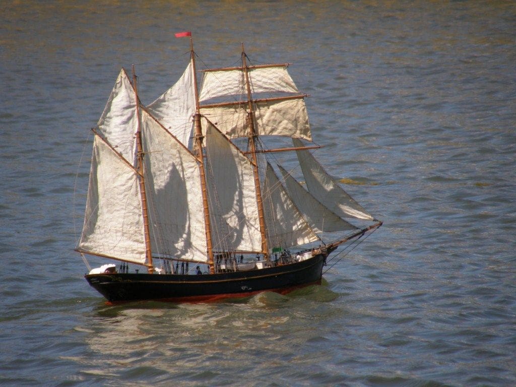
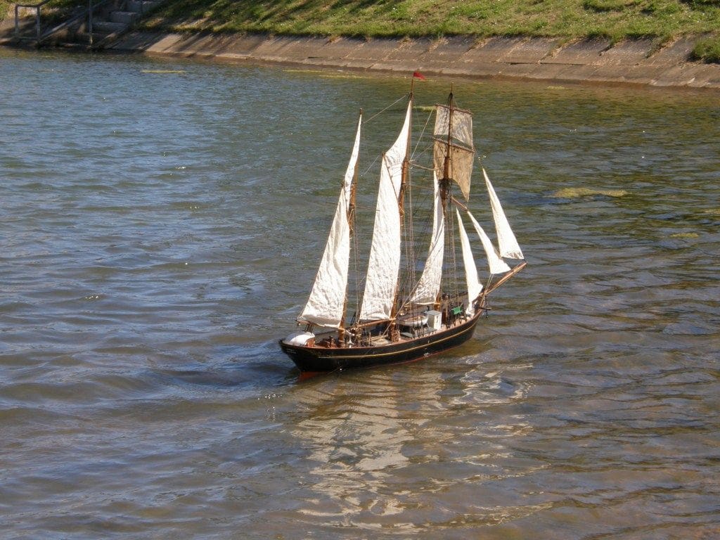
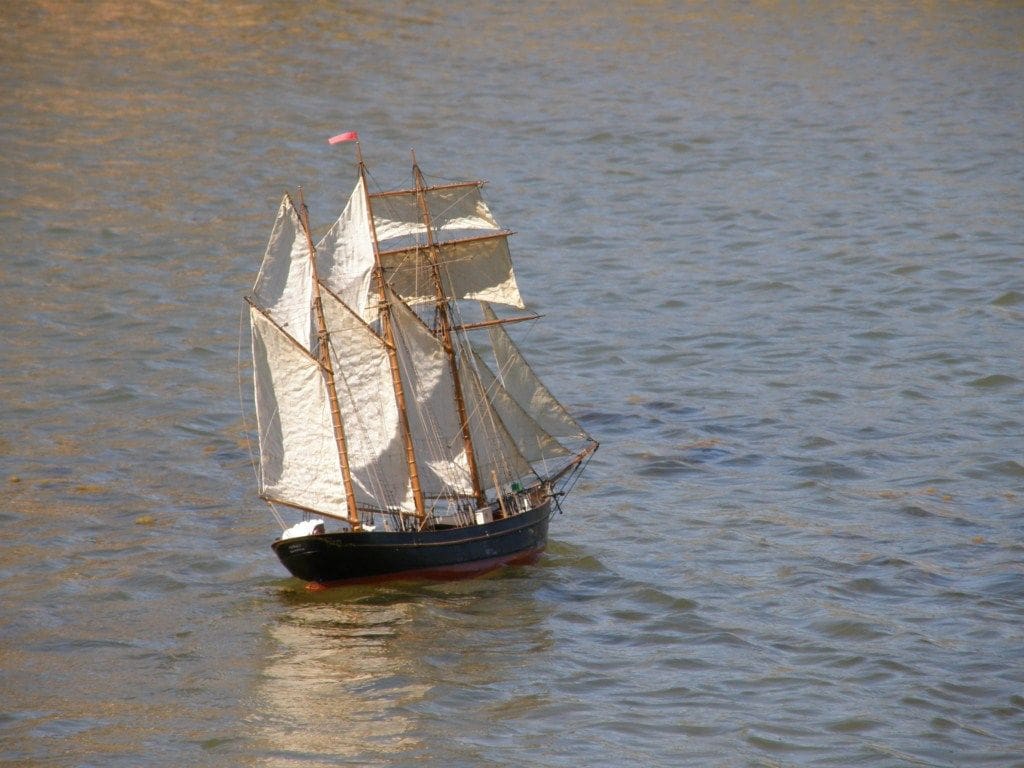
Performance
The model sails well on all points of the wind and looks splendid going fast in a good breeze, Like the full-sized ship she can be a bit wet and so I made hinges for the freeing ports which work very well at getting rid of water from the deck. However, she takes her time when altering course which can be worrying when operating on a hard-edged model boat pond. To minimise the risk of damage, I altered the support for the bowsprit so that hopefully it will collapse aft in the event of a direct serious encounter with an unforgiving concrete wall. Otherwise, I am very happy with the model and enjoy sailing her. The completed model, Photo 20, was awarded a Gold Medal at the International Model Engineer Exhibition of 1995 and has remained fully serviceable since then and is still in current use.