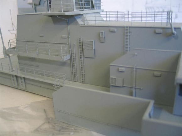
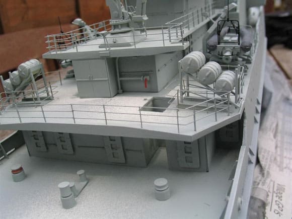
Pic 1. The main parts of the superstructure completed with some of the fittings placed in position. Pic 2. A simple and useful method of identifying the structural detail against the drawing. Pic 3. The laptop allows images to be enlarged and highlighted. Pic 4. The digital card viewer is also a useful tool that easily fits into a workshop environment. Pic 5. Like the laptop pictures can be selected and enlarged.
Part Three – HMS Mersey
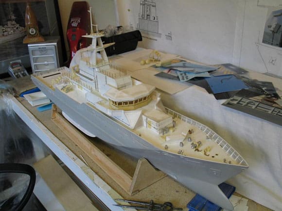
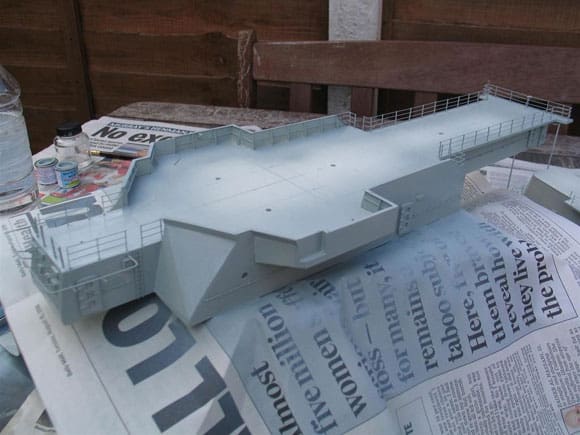
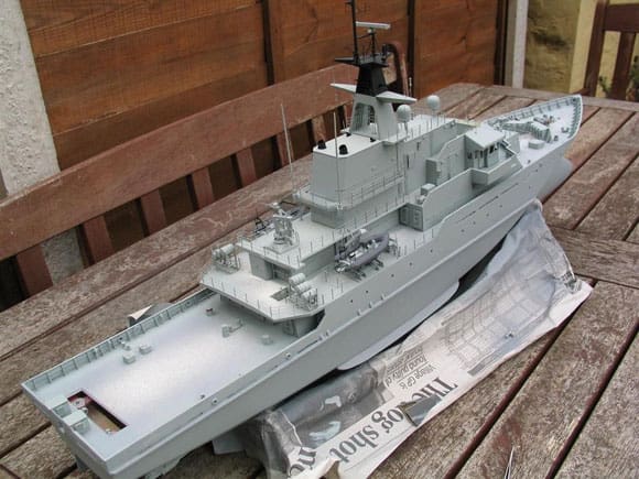
In part two much of the construction and preparation work had been completed and the superstructure had been temporarily placed in position along with many of the larger fittings. Other fittings, such as the marker lights, life ring dispenser, deck eye plates and associated marker lights were left till much later in the build, Photo 1.
Some useful aids to building
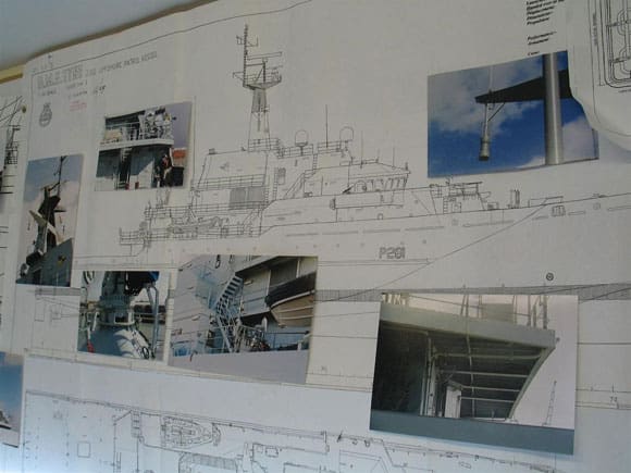
Before continuing I’d like to mention three of the methods used as aids in identifying parts of the vessel in relationship to the drawings. Photo 2 illustrates a well tried low-tech method whereby photos of the original vessel are ‘Blu Tacked’ as close as convenient to the relevant part on the drawing. I understand that this is not always possible because of availability of photos or access to the vessel but none-the-less it is a very useful aid to building.
Enjoy more Model Boats Magazine reading in the monthly magazine.
Click here to subscribe & save.
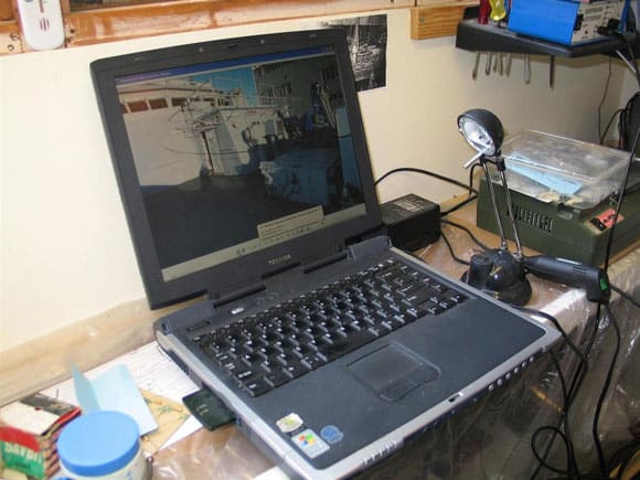
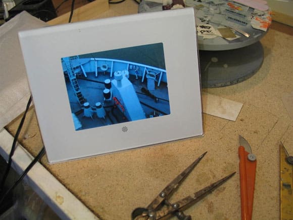
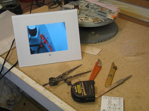
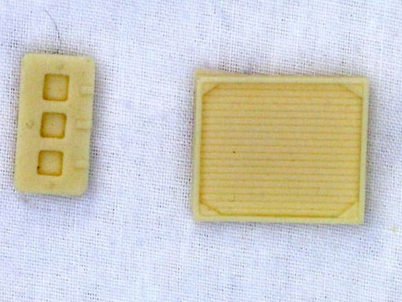
Another method gaining favour is in the use of a PC, or laptop, as shown in Photo 3. Pictures can be shown from a CD or those stored on the hard drive and can be brought up for viewing as and when required. There is also the PV or Picture Viewer which retains some of the advantages of a laptop for displaying pictures yet alleviates the need to bring a laptop into a workshop environment. Here pictures of a vessel can be brought up direct from the card / scan disc with individual pictures being selected and displayed as in Photo 4. Having a zoom facility you can go right in to the picture to pick out the fine detail, Photo 5. This in no way replaces the CD or even ‘hard copies’ but it is an additional tool for the job and a less expensive alternative to the PC or laptop, but does have the single disadvantage of only operating with the camera memory card.
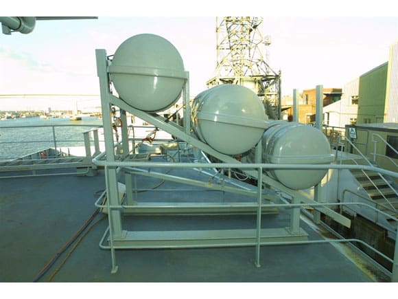
Pic 6. The front of the forward deck housing taking shape. Pic 7. Sloping front of the forward deck housing on Mersey. The rails surrounding this area can be fitted with netting. Pic 8. This large 25 ton capacity container crane is sited aft of 01 deck. Pic 9. A single piece resin moulding of the container crane. The hydraulic arms are cast in white metal. The remainder of the detail is at the discretion of the modeller. Pic 10. Spray-painting a light primer coat on the superstructure using WEM RN modern grey.
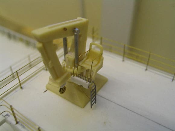
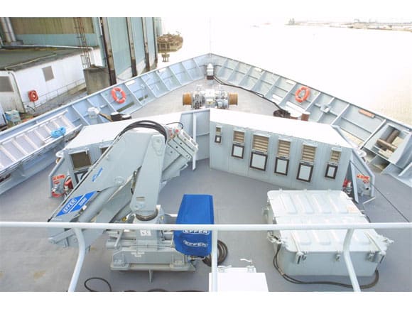
One-piece resin moulded crane
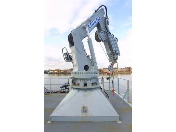
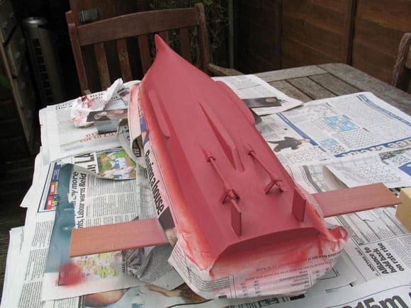
Once again and as a reminder Photo 6 shows the stage of construction reached as per last month. At this stage various deck fittings, such as vents can be positioned prior to giving the whole model a primer coat, with Photo 7 focusing on the same position as shown in Photo 6 . Sirmar produce the two distinctive ‘Effer’ type extending jib cranes. This is a one-piece moulding and like much that is resin there is room for enhancing the basic fitting. Photo 8 shows a good view of the crane that is fitted aft. The starting point is to add to the basic seating arrangement. Other item such as hydraulic piping, operating fitments, will to be added later, Photo 9.
Preparation for airbrushing
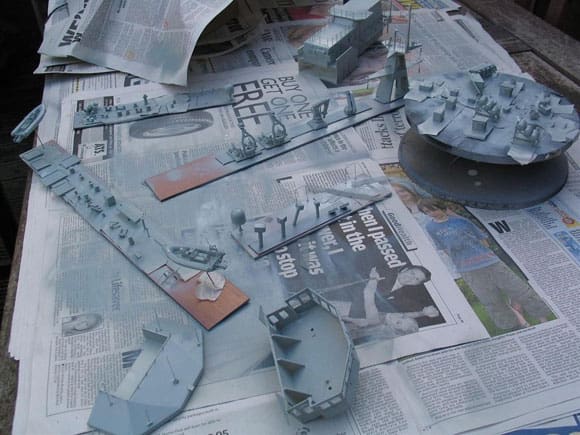
Mixing the right shade of RN grey can be rather problematic. Modern paints used by the RN have a high degree of reflectivity, so getting the formula right is important to achieve the best results. To circumvent the need to mix, White Ensign produce an excellent range which includes modern RN paint finishes MO-1 light grey and MO-2 deck grey which will be discussed later; both match exactly the shades in current use. Preparation for air brushing follows a well-trodden path where most of the essential deckhouse fittings, as demonstrated in part 2 are fitted into place, Photo 10. For individual fittings the use of short lengths of timber and or a revolving turntable helps in allowing each fitting to be air brushed evenly. The fittings can be mounted on double-sided tape, masking tape or even Blu Tack, Photo 11.
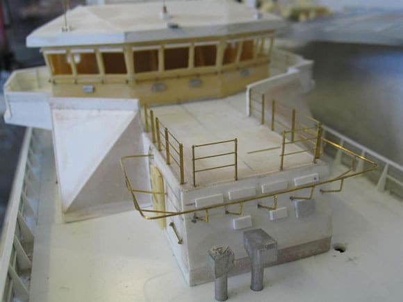
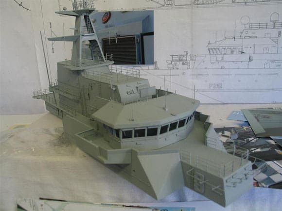
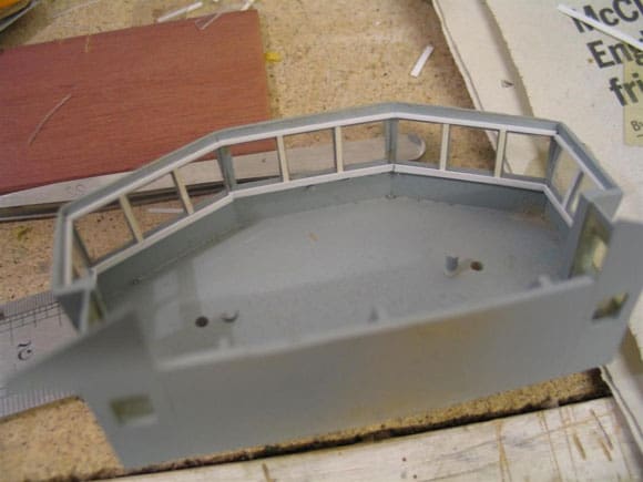
The next stage is to put all of the superstructure temporarily together, Photo 12. Using Photo 13 it will be noted that the open area above the bridge has a glass screen. For the model this was made up using evergreen 1mm sq. strip that forms the screen supports and strips of 10 thou acetate, 4mm wide, and cut to conform with the surrounding edge – being aware the screen slopes outwards, Photo 14.
Deck and deckhouse fittings
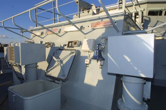
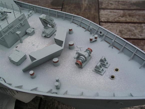
Many of the deck fittings such as the bollards and winch can be prepared with each of the bollards and winch gypsies painted in a ‘rust type’ shade to represent that seen in Photo 15 , the results of which can be appreciated in Photo 16. Incidentally none of the deck fittings are positioned until the deck laminate is fitted in place. In part 2 mention was made of the shape of the breakwater (difficult to determine on the drawing). Photo 15 help to define its true appearance. Akin to many ships Mersey has much exposed pipework, ladders and other smaller fittings like bulkhead lights, all of which were fitted prior to painting. A single coat is applied, which can be called a primer coat, but essentially it’s the same paint that will be used throughout the model (see above). Photo 17 shows the results of a single coat with the fittings being highlighted and not submerged as can happen if too many unnecessary coats are applied.
Pic 11. Various methods used for spray painting, see text. Pic 12. Once the superstructures are prepared each part is placed in position. Pic 13. 02 deck on Mersey directly above the bridge, with the binnacle in the centre of the picture. Pic 14. Atop of the bridge. Here the bridge roof is slotted into place to marry with the outer side of the superstructure. Pic 15. The forecastle deck as seen on all the Batch 1 River class. Note the shape of the breakwater.
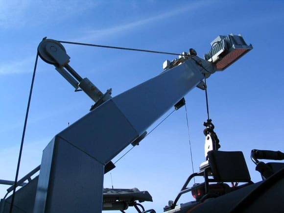
Davits
As shown last month the davit arrangement comes as a one-piece moulding but as stated above does not consist of the floodlight at the head of the davit. Also added was the pulley wheel for the topping lift, Photo 18. This can be seen from a position looking aft on the starboard side. Note in the foreground the power pack and controls for operating the davit, Photo 19. The partly completed assembly for the davit arrangement can be temporarily put in place. Note the power pack in this photo which is made up from styrene strips and aluminium tube seen to the right in Photo 20.
Further aft on the main deck
Moving aft on the main deck is the opening and stairway down to the cargo deck. Once again all of these fittings are temporarily placed in position, Photo 21. However for those wishing to build one of the River class I’ve included a detailed photo of the area adjacent to the stairway opening. As you can see there is more detail to add. In fact having such pictures can be an advantage or a curse as there is so much that has to be taken into account. The hose dispenser is but one example, Photo 22.
Life raft dispensers and vents
The construction of these was shown in part 2. Photo 23 however shows the frame in detail.
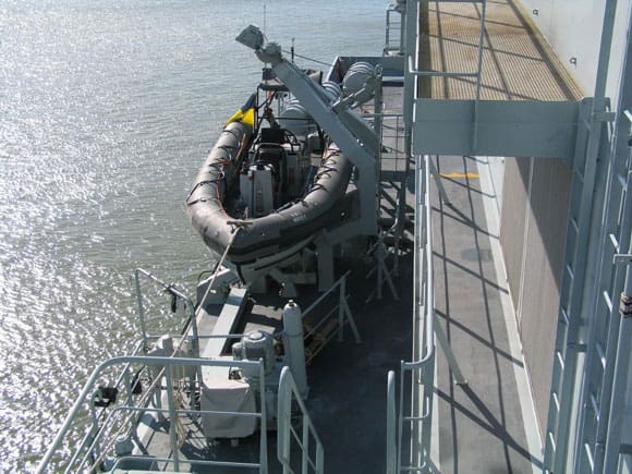
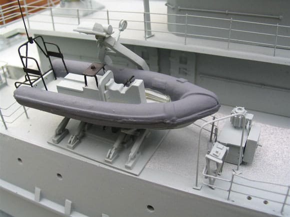
Pic 16. Some of the fittings placed in position on the forecastle deck. Pic 17. Starboard side of the superstructure. The smaller vent grills are painted in situ, see text for colour mix. Pic 18. The topping lift for the davit, also the red floodlight on the head of the davit. Pic 19. Looking aft on to the starboard Pacific 22 RIB. Pic 20. In their basic form the moulded RIB positioned (but not fixed) along with other items that form the davit arrangement. The sides of the rib are painted a base WEM dark grey, see text.
The areas covered thus far can be appreciated in Photos 24 and 25. There are a number of items that are best left until a later stage. For example the large vents seen just beneath the walkway around the uptake. Sirmar/PSShips provide these as part of the fittings pack, Photo 26, and can be prepared using a mix of Humbrol Matt 94 and 180 for the vent panels and Humbrol 11, metallic silver, for the outer frame. The results of this can be seen in Photo 27 with two of the vents set in place. Note the effect of the light conditions on the paintwork.
Fitting out the bridge and glazing
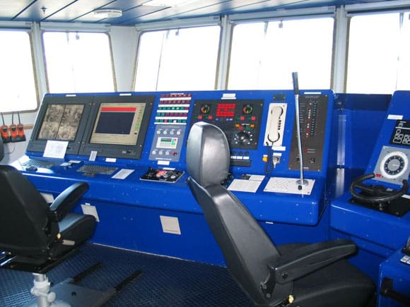
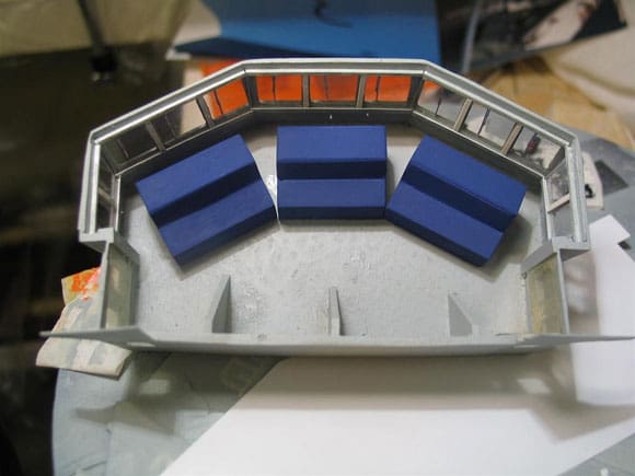
Originally the aim was to just glaze the bridge windows and fit the wiper blades, leaving aside interior fitting, as it was assumed these would be hidden. However on viewing a picture of the bridge it became clear that part of the interior was indeed visible. The reason for this is simple. The interior is fitted out with control consoles finished in a bright blue coating, clearly visible from the outside, Photo 28.
Pic 21. The first primer coat applied and some of the larger fittings placed temporally in place aft. Pic 22. Aft of the main deck (see pic 21). This picture highlights the details that’s yet to be added. I wish BECC could add more HS signage to their expanding range in 1:96 scale as per that shown in this pic. Pic 23. The type of life raft container and the storage rack seen on the River class. Pic 24. Looking aft towards the starboard RIB position on Mersey. Note the intake grills beneath the walkway surrounding the uptake. Pic 25. The entire model is coated overall in WEM RN modern grey.
Glazing the bridge windows.
Glazing can become a problem as any adhesive, even Clear Fix, can be seen if exposed on the acetate glazing. The solution was to make window frames that the acetate sheet cut to size could slide into, and the frame sealed in place, Photo 29. The glazing fits between the horizontal members whilst the vertical sections slot tightly into place against the acetate. A very small drop of styrene cement is applied to the back of those joints. No adhesive whatsoever comes into contact with the acetate. Each of the control consoles were made (not accurately I hasten to add) from styrene sheet. So long as they were just visible from outside they would fulfil their purpose. Accuracy here was problematic as much of the real detail is certainly invisible when viewing from the outside, Photo 30. Thus only the bare outline painted blue (Humbrol 25) was necessary. Of course the interior could be taken that one step further but the top of the bridge would have to be removable, which was not considered practical.
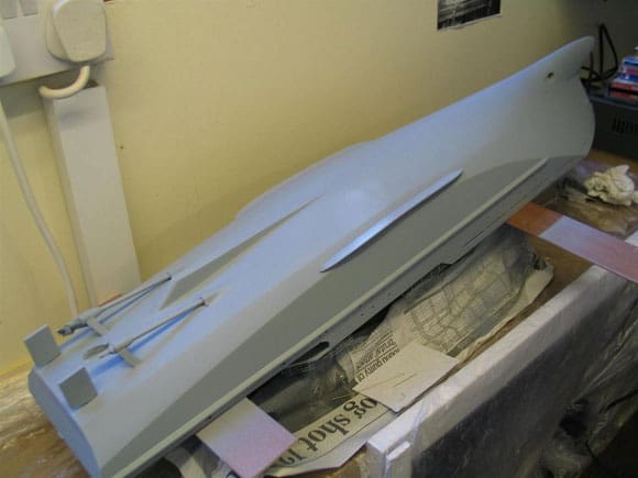
Anti Foul
The hull was air brushed for a second time and left to dry. Unlike the Humbrol paints WEM enamels are based on a different formula and require no thinners. However the curing time can be as much a six hours. In so doing the preparation for the anti foul did not take place for at least 24 hours. The underside of the hull was made ready to receive the Humbrol 73 (matt wine), the prop end of the shaft was sealed and the hull was given a light rub down with flour paper, Photo 31.
Preparation
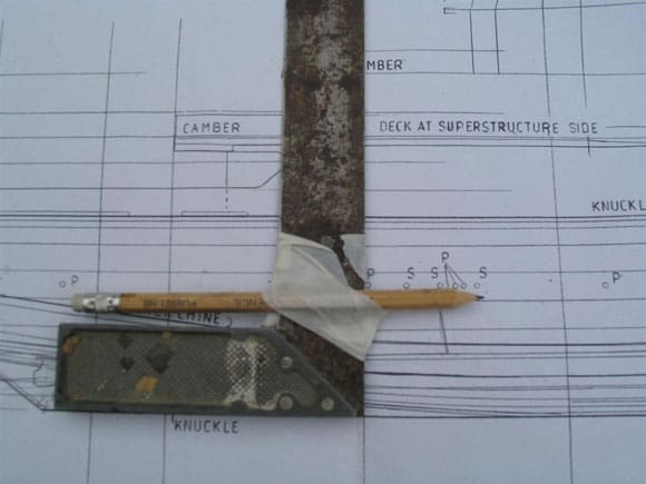
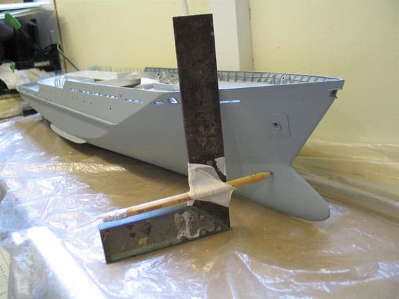
Marking out the position of the anti foul is a straightforward task. Here simple tools are used together with the drawing to set the exact level of the anti foul up the side of the hull, Photo 32. The hull is placed on a level surface and the pencil is used to mark various points along the hull. A low tack tape (Tamiya type) is used with the tape being fed from one mark to the next. At first it may not look at all level but if the hull is on a level surface it will in fact be correct, Photo 33. The upper part of the hull can be covered over with the underside now ready to be coated with Humbrol 73. It’s worth noting that the hull is lifted well clear of the work bench, Photo 34. That’s it for part 3. In the concluding part of this short series there are more tips on finishing, presentation, making a simple carry case and of course the all-important sea trials.

Pic 26. The various sizes of vents seen on the side of the superstructure and uptake are available from PSShips/Sirmar and moulded in resin. Pic 27. This picture is an example of the effect of light on the type of paint used. This is the same effect seen on the full size vessel under the same conditions. Note the vents in position. Pic 28. Part of the bright blue coloured control console seen on the bridge of HMS Mersey. Pic 29. Glazing the bridge windows. Pic 30. As the bright blue of the control console is clearly visible this was reproduced in the model. Pic 31. The underside of the hull being made ready for air brushing the anti foul. Pic 32. The level of the anti foul is lifted from the profile drawing. Pic 33. Each side of the hull is marked along the length to the level of the anti foul. Pic 34. Using low tack tape the level of the anti foul is masked off, the upper part of the hull covered over and the underside sprayed Humbrol 73.
References and Acknowledgements
WHEC 33 Duane; ref. Ships and Aircraft of the US Fleets 13th edition by Norman Polmar, pages 501 to 502.
US Warships of WW2 by Paul H Silverstone, pages 373 to 375.
Furieux; ref. Conway’s All The World’s Fighting Ships 1860 –1905, page 300.
TF 72 Australia – Michael Brown.
First published in Model Boats number 4, April 2007


