Pic 1: Single channel set (photo by Dave Wiggins). Pic 2: Multi channel set (photo by Dave Wiggins). Diagram 1. Frequency hopping diagram.
The widespread availability and rapidly dropping prices of the new 2.4GHz radio control equipment seems to have raised many questions on the various web forums about how different this equipment is from the older sets and the benefits or otherwise of using it in boats, so this seems to be an appropriate time to offer an overview of the situation.
Brief history
Lets first do a quick gallop through the history of radio control. The story takes us from 1950s and 1960s single channel sets, Photo 1 (by Dave Wiggins), with the earliest using valves and rubber or clockwork powered actuators to the present generation of equipment using integrated circuits and containing a substantial amount of computer power. Transistorised single channel sets were commonly available in the 1960s ( I had one, a MacGregor set -Editor).
Enjoy more Model Boats Magazine reading in the monthly magazine.
Click here to subscribe & save.
I first came across r/c gear in the 1960s, when single channel bang-bang sets were the only thing available. By the way, the bang-bang referred to the noise the actuator made when changing from one state to another. The rudder actuator stepped through the sequence Centre – Left – Centre – Right – Centre at each press of the transmit button, so if you steered left and then wanted to steer left again you had to flick quickly through right first. The first multi-channel sets, Pic 2 (by Dave Wiggins), relied on transmitting different tones for different channels and separating these in the receiver by using a set of tuned reeds (rather like tuning forks), but these still didnt allow proportional control as we know it. The big breakthrough came with digital proportional sets using servos and allowing accurate control of steering and throttle via joysticks. Developments since then have refined and expanded the capabilities of this technology.
Digital proportional control
The earliest sets used the 27MHz band more or less successfully until the craze for illegal American CB radio occurred. Then the imported CB rigs, which used the same frequency band, caused havoc with model r/c sets. This led to the introduction of two additional bands, 35MHz specifically for aircraft and 40MHz for surface vehicles (including boats). The 27MHz band originally used AM (amplitude modulation) and FM (frequency modulation) was only introduced later, whereas the 35MHz and 40MHz bands used FM from the start. AM sets are much more prone to interference than FM and are now largely superseded, except for use in some cheap RTR models.
AM, or amplitude modulation, relies on varying the level or size of the signal transmitted on a fixed, crystal controlled frequency, to transmit information to the receiver. This is very susceptible to fading, in a similar way to a weak medium wave broadcast signal and to being overridden by a stronger unwanted signal.
FM, or frequency modulation, uses a special circuit to slightly alter the frequency of the transmitted signal in response to changes in the information to be transmitted. This is much less susceptible to fading as the received signal strength can vary quite widely without preventing the receiver decoding the changes in frequency. An effect known as capture also helps to make the signal more resilient in the face of another signal.
With improvements in technology, in particular the miniaturisation of receivers, this was the situation until the 21st century. There had been another couple of bands available for many years, but the technology to exploit them hadnt been available at reasonable consumer prices. In recent years, equipment for one of these bands, 2.4GHz, has started to become available with Futaba, Pics 4 and 5, and Spektrum, Pics 6 and 7, first in the field. The practical use of this band has been driven (as has so much else) by the computer industry. Computer wi-fi and Bluetooth equipment uses the same 2.4GHz band and so a lot of money has been spent on research into the associated technologies. The spin-off from this research is benefiting model radio control users. In fact many professional remote control units have been using similar technology for years.
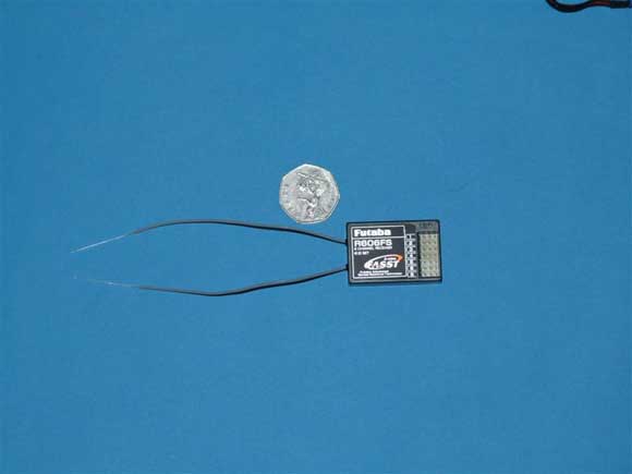
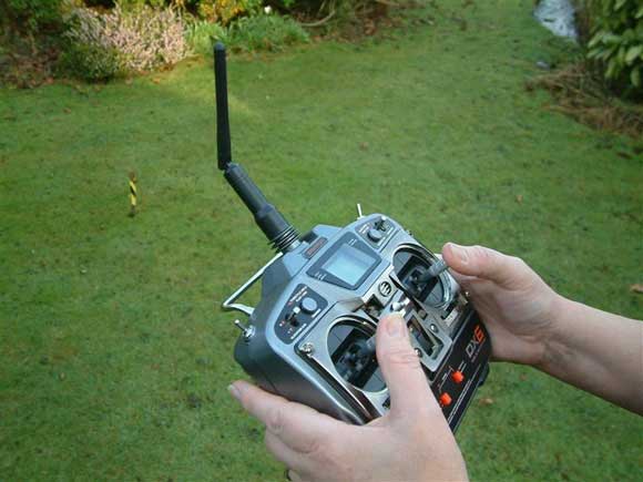
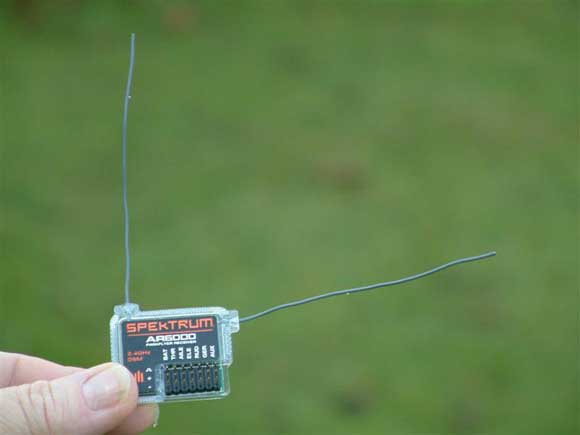
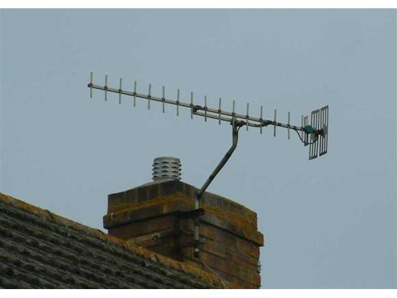
Pics 4 & 5: Futaba 6EX 2.4GHz transmitter and receiver (Photos by Dave Brumstead). Pics 6 & 7: Spektrum DX6 transmitter and receiver. Pic 8: Vertical TV aerial. Pic 9: Horizontal TV aerial. Diagram 2: DSM spreading diagram. Diagram 3: DSM despreading diagram. Diagram 4: Radiation pattern of transmitter aerial.
2.4GHz technology
Now lets have a look at a few details of that technology. The first obvious thing is that the aerials on the transmitter (Tx) and receiver (Rx) are both much shorter than those on traditional units. This is the first clue to the main difference, because 2.4GHz is in the microwave band and 40MHz is in the VHF (very high frequency) band.
Frequency is directly related to wavelength, which is often easier to envisage. For instance Radio 4 long wave is on 198KHz (K = 1000) or 198,000Hz and its wavelength is about 1500m, whereas 40Mhz (M = 1000,000) is 40,000,000Hz with a wavelength of 7.5m and 2.4GHz (G = 1,000,000,000) is 2,400,000,000Hz with a wavelength of 0.125m or 12.5cm.
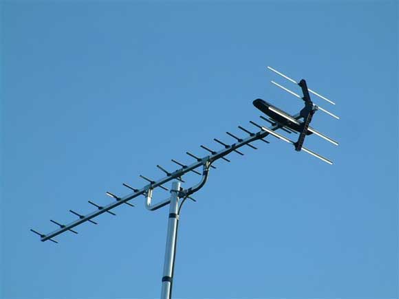
We can now see why a standard 40MHz transmitter has a whip aerial over a metre long whereas a 2.4GHz set has a little stub aerial just a few centimetres long. Turning to the receiver, the most obvious thing is that it not only has it got a very short aerial, but it also has two. This is because of a very neat trick used for many years in professional radio links to or from moving units. A good example would be a radio microphone or the handheld cameras used at sporting events. In these cases, its the moving unit which is transmitting, but the principle is exactly the same if the receiver is moving. All radio transmissions are polarised. This means that they are stronger in either the horizontal or vertical plane. Just look at your local TV aerials. Theyll either have the elements vertical, Pic 8, or horizontal, Pic 9. This is because some TV transmitters use horizontally polarised signals and some use vertical. The relationship between the transmitter and receiver aerials is fixed. However once one or both are moving and changing their relationship to each other (think about aerobatic model aircraft) then this situation changes and the polarity becomes jumbled and varies continuously. The obvious fix for this would be to have two receivers, one with a vertically polarised aerial and the other with a horizontally polarised one, compare the outputs and switch seamlessly to which ever had the strongest signal at any moment. In essence this is what the 2.4GHz sets do, though practical circuits are somewhat more complex and have other refinements as well. The reception unit is actually two receivers in one case with the extra electronics to do the comparison and switching. We now have the reason why the two aerials should be arranged at right angles to each other with one vertical and the other horizontal, see Pic 7 again.
There are a couple of other bits of electronic wizardry as well. There are no swappable crystals in a 2.4GHz set. Thats perhaps nothing special as there are plenty of 40MHz synthesized sets around these days which use a very stable, but adjustable circuit (the frequency synthesizer) to generate a selectable channel instead of crystals. Perhaps more surprisingly, there isnt a control to automatically set the channel in use either, even though the blurb says that youll never have a channel clash with another boater.
The buzz-words are frequency-hopping and spread spectrum. Again the principles have been around for years and were originally developed to make it difficult to intercept battlefield communications and later to cram more users into a limited number of channels. So far, the two manufacturers in the model r/c field, adopt different approaches and both naturally claim that theirs is more robust.
The Futabas FASST (Futaba Advanced Spread Spectrum Technology) system uses frequency-hopping, Diagram 1. This technique utilises the 80 available channels all the time, randomly switching channels seamlessly every two milliseconds. The idea of this is that if theres interference on any channel, it will only be a problem for 2ms at a time. Other circuitry in the receiver fills in any lost data.
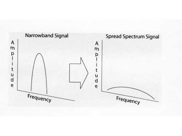
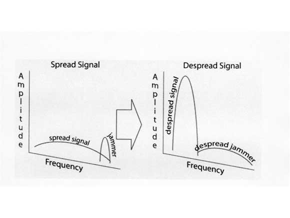
The Spektrum system takes a different approach. Their system is described as DSM/DuaLink (patent pending). With DuaLink, the transmitter randomly selects two clear frequencies from the band, locks on to these and transmits the same information on both simultaneously. If one transmission path is corrupted by interference or poor alignment between transmitter and receiver aerials then the other one is almost guaranteed to be ok. The DSM in the Spektrum specification stands for Digital Spread Spectrum, Diagram 2. In this case, rather than frequency hopping, the transmitter adds random noise (pulses of much shorter duration than the required data bits) to the signal. These are filtered out at the receiver to recover the data. The addition of the noise component, spreads the narrow data signal out and makes it much less susceptible to interference, which tends to be narrowband. During reception, the noise component is subtracted to leave the original data signal. The converse also occurs and a narrow interference signal is spread out reducing its effect, Diagram 3. As with the Futaba set, the receiver unit contains the electronics to reconstruct the best output from the available input signals.
Range and installation
Next lets look at the matter of range and installation. The first thing to note is that the aerial length is critical and shouldnt be altered. Whether in time therell be sets fitted with sockets, so that aerials similar to those used for other 2.4GHz applications could be used remote from the receivers, I dont know. I suspect that the problem doesnt exist in the model aircraft world and that the limited number of sets used in model boats will mean that its unlikely. Secondly we all know from our microwave ovens that signals in this range of frequencies are absorbed by water molecules much more readily than 40MHz. If that wasnt true, then microwave ovens wouldnt work. Hence the range over water is likely to be less than over dry ground. Gossip on the forums has it that the range in boats is at least out as far as British Standard Eyeball visibility, which should be enough for most of us. I would suggest that the most important thing is to keep the receiver as high up in the model as possible. Those intending to use these sets in boats with high superstructures like tugs and lifeboats may want to consider mounting the receiver in the superstructure rather than in the conventional place within the hull. The small size and light weight of the receivers makes this particularly easy. I would also emphasize the desirability of keeping the aerials at 90 degrees to each other.
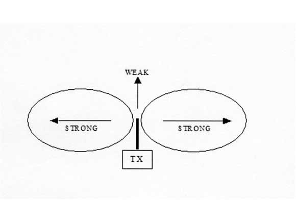
However, ideally these should not be fixed to anything, as this will almost certainly reduce the sensitivity. Its also worth adjusting the angle of the transmitter aerial so that its vertical when the transmitter is held comfortably in the hands. This is because the radiation pattern of the aerial is rather like half a doughnut with the hole surrounding the element, Diagram 4. This means that the weakest signal is transmitted off the end of the element.
The easy absorption of the signal by water also accounts for the warning about not holding the transmitter in such a way that the fingers touch the aerial. While the transmissions wont actually cook human flesh, most of the transmitted power will certainly try to do just that. Leading on from this, I cannot imagine that there is any hope of using 2.4GHz for submerging model submarines.
On the subject of transmitter power, there was some concern that these sets may transmit at higher power than is legally permitted on the 2.4GHz r/c band in the UK. In an unusually helpful move, the regulatory body OFCOM has raised the UK permitted limit to 100mW, which is above the output power of both the Futaba and Spektrum units.
Conclusion
This has been a quick overview of the present situation, focusing in particular on the new equipment now becoming available. I have deliberately written it for the non-technical reader and in doing so made some simplifications and glossed over some points. I mention this because any readers out there with a background in RF and electronics will certainly be able to pick holes in my explanations or already have more in-depth information. In particular I have used the term random when in fact it would be more accurate to say pseudo-random.
Both the Futaba and Spektrum sets have very comprehensive channel mixing options and other goodies. These will be of particular interest to scale sail modellers as they allow very flexible control of multiple sail winches and servos. I hope to offer a report on the Spektrum DX6 equipment for a future issue and will cover some applications of these facilities in that article.
Useful websites
Wikipedia: Spread Spectrum For a more technical explanation of Spread Spectrum and DSM, interested readers could do worse than start from this Wikipedia entry.
OFCOM This website page with general information on r/c bands in the UK.
Spektrum DX6 Resource Center Excellent technical article on Spread Spectrum technology with particular reference to the DX6 set.
Spread Spectrum Scene Technical article on various spread spectrum techniques.
The ED Story – Radio Control Units, Kits, and Accessories Article on 50s and 60s r/c equipment from the British manufacturer ED (Electronic Developments).


