How she developed, or a ‘Comedy of Errors’!
PHIL BUTTON’S scratch-built steam model, 1996 to 2011

Many model builders do not like to admit that things have gone wrong during their build of a particular model. Like our Model Boats regular contributor Glynn Guest, I am always worried when things have gone rather too well, and keep waiting for the inevitable problem to bite me, as inevitably it will! This is the brief tale of my longest build to date and is intended to give hope to anyone who may be struggling to keep on until the bitter end.
Enjoy more Model Boats Magazine reading in the monthly magazine.
Click here to subscribe & save.
Having sampled the ‘delights’ of model aircraft in my youth and found that I lacked the necessary patience to build them correctly (at the time that is, as things seem to change as one gets older) and then having frequently suffered the ignominy of taking them home in many pieces, since I also found that I also did not fly them very well either, I changed over to model boats a good number of years ago. With a model boat, you can usually recover it and carry out repairs if and when disaster strikes.
I am also a Chartered Engineer, electrical as it happens, but any engineer is first and foremost an engineer, and I found an interest in steam power at a very early age. In particular, I have always been fascinated by paddle steamers and the thought occurred to me that a live steam paddle steamer would be rather fun to make. As I have built up a well-equipped workshop over the years, producing my own steam plant is not too great a problem.
So, in 1996 I started looking for a suitable engine design around which to build a model. The E T Westbury design for a double diagonal paddle engine (as published at that time by Model & Allied Publications) looked as if it would fit the bill and a set of drawings and castings was ordered from A J Reeves in Birmingham.
Hull
Whilst awaiting delivery of the castings, the next requirement was to find a suitable hull. A trawl through my archives produced a feature article including a hull lines drawing by E W Paget-Tomlinson for an American Civil War blockade runner by the name of Hope. I cannot remember whether this was in Model Boats or Model Engineer as I took both magazines at that time. The original drawings were printed out across two A4 size pages at roughly 1:400 scale and had to be blown up (using a photocopier, not dynamite!) to match the overall dimensions of the engine to around 1:40 scale, giving a hull length of 1800mm or 72 inches in good old Imperial.
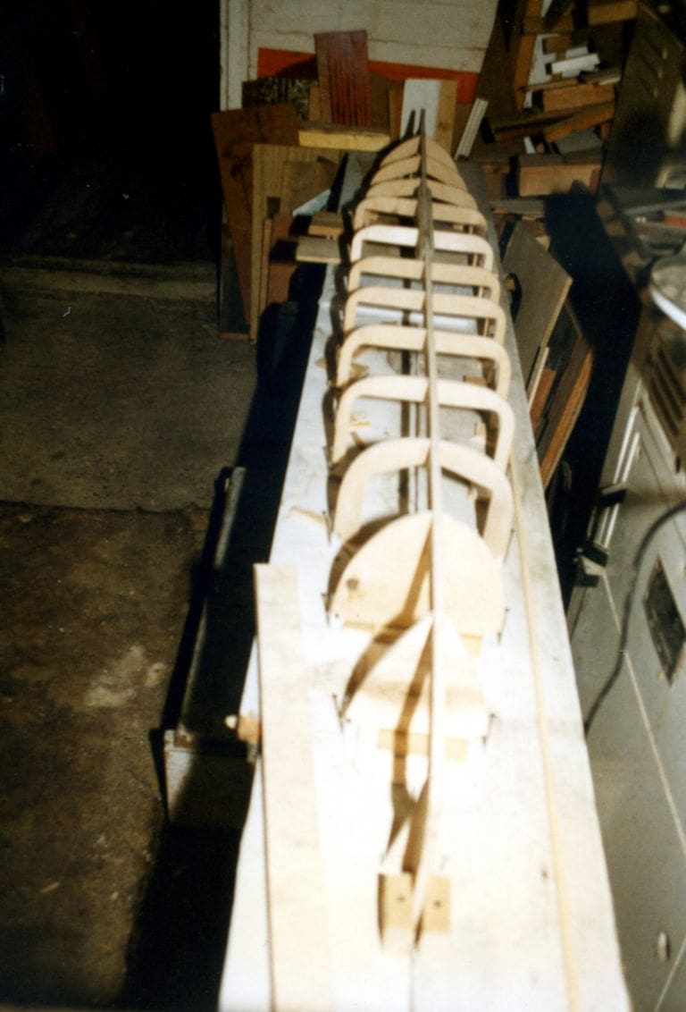
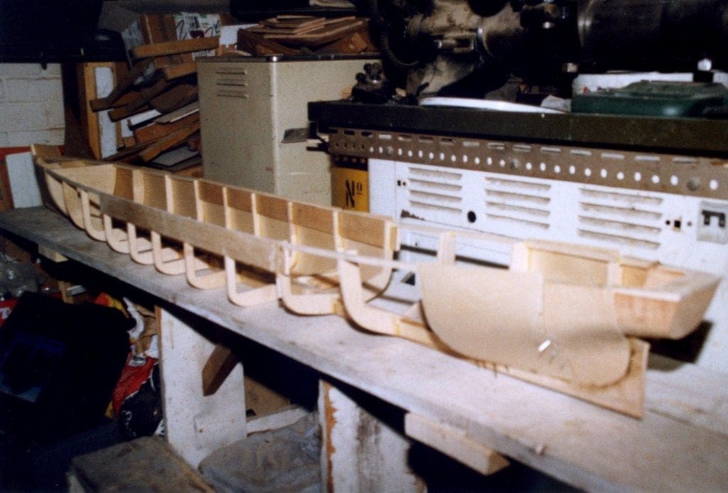
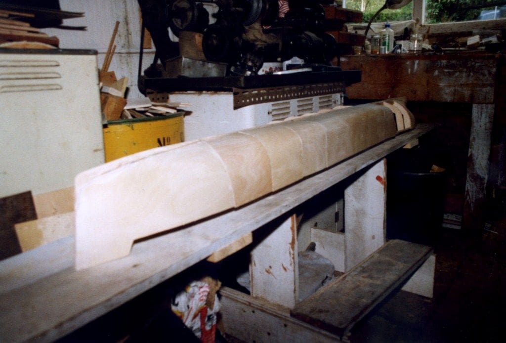
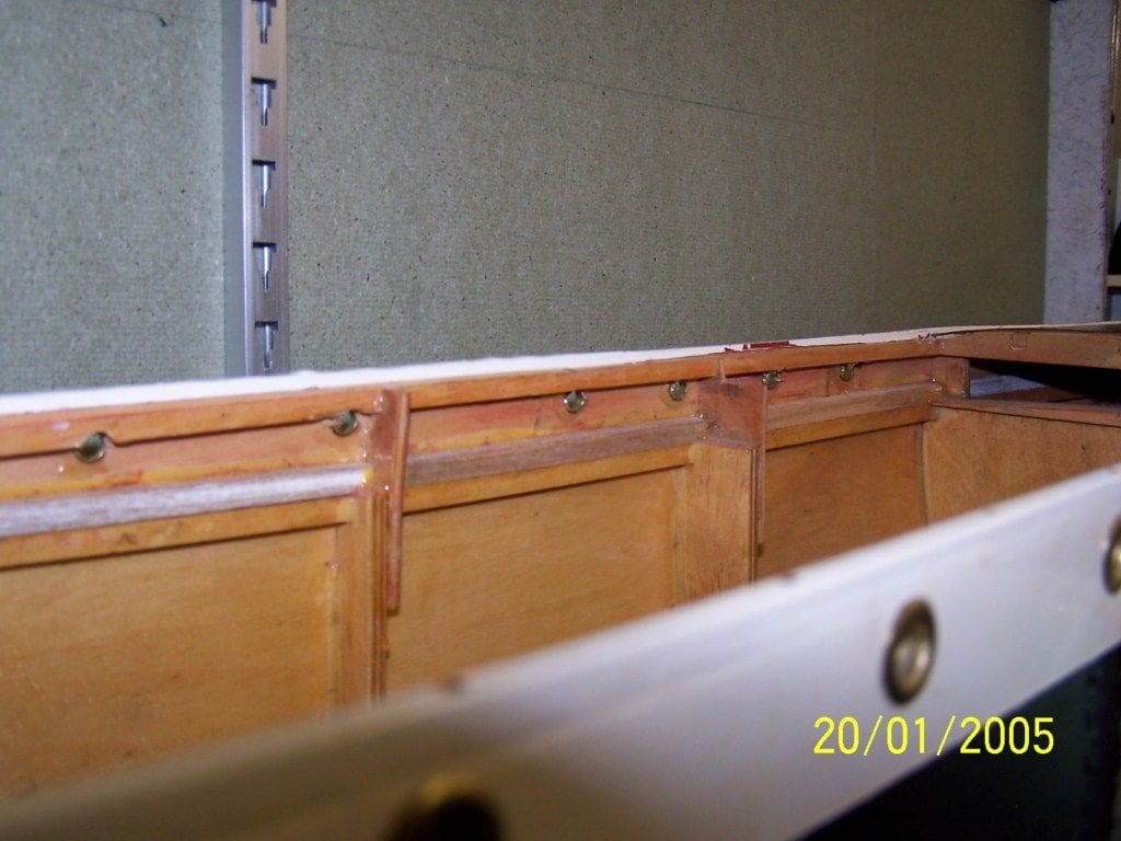
I made up a set of drawings for the ship’s keel and its many bulkheads and proceeded with constructing the hull up to the point where, it had been fitted with the outer skin and given a coat of sanding sealer to waterproof it, by the closing months of 1997. I am not including a blow by blow account of hull construction, other that it was a framework covered with 1.5mm ply skinning put together in the conventional way. Photos 1 to 3 show some the basic framework and the 1.5mm skin being added. I apologise for the poor picture quality as these were taken some 15 years ago and before I turned my hand to writing for MB.
Engine and boiler
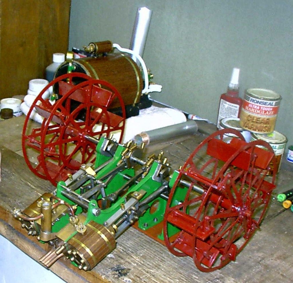
There then followed a long break from woodwork whilst I machined and fitted the hundreds of parts making up the paddle engine and then tested it and ran it in on compressed air. I built up a set of feathering paddle wheels to seven inch diameter rather than the 5.25 inches shown in the Westbury drawings in order to suit the wheels to the hull dimensions. This phase occupied pretty much two whole years when fitted in around my day job and Photo 4 shows the completed paddle engine with the wheels. It wasn’t all quite that easy of course!
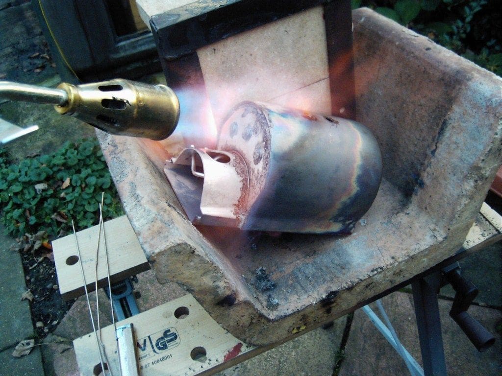
I designed a launch type boiler to suit the estimated steam requirements of the engine and then built that up from copper tube and sheet with phosphor bronze longitudinal stays and bronze bushes for the various boiler fittings. This took approximately six months to complete. To build this monster boiler, I had to buy a propane-fired roofing torch of around 50kW output as DIY blowtorches definitely would not have done the job. Photo 5 shows the boiler being set about with the gas torch and Photo 6 shows the completed boiler with steam pipes and manifold. Photo 7 shows the boiler installed in the hull.
Would the model float?
I was now about seven years from my first thoughts of building a paddle steamer and was able to weigh the engine and boiler, then add to that an estimate of the likely weights for radio control gear, superstructure, power plant pipework and fittings.
Since the hull (remember it’s 1800mm long) was rather too big for the domestic test tank (the bath), a trip had to be arranged to one of my local boating lakes. This trip required the co-operation of my son-in-law since he owned a van and the hull would not fit in my car. The hull had been temporarily marked with the desired waterline and was weighted down to that level using test ballast in the form of bricks. On returning home, the bricks were weighed and checked against the weight of the kit to be installed and yes, a disaster, as the hull could nowhere near carry the proposed steam plant installation.
This setback resulted in a complete re-think of the entire design, including:
1) Build a different paddle engine and boiler combination of less weight, which would be rather a lot of work.
2) Build a bigger hull to carry the power plant, but since the existing hull did not fit the car to begin with, a bigger one could therefore not be made in one section thus leading to all sorts of problems.
3) Consider a completely different model, based on the hull as built and just maybe, keeping the boiler?
After much thought, I elected to try and find a vessel with a similar hull shape to the one that I had expended so much effort on when building it. The paddle engine was consigned to the pending drawer for attention at some future date and it’s still there, but the boiler could possibly be retained. Since the original hull shape was that of a late Victorian Clyde-built paddle steamer and hence long and narrow, I started looking at pictures of other Clyde-built ships from the same era. Two ships in particular stood out:
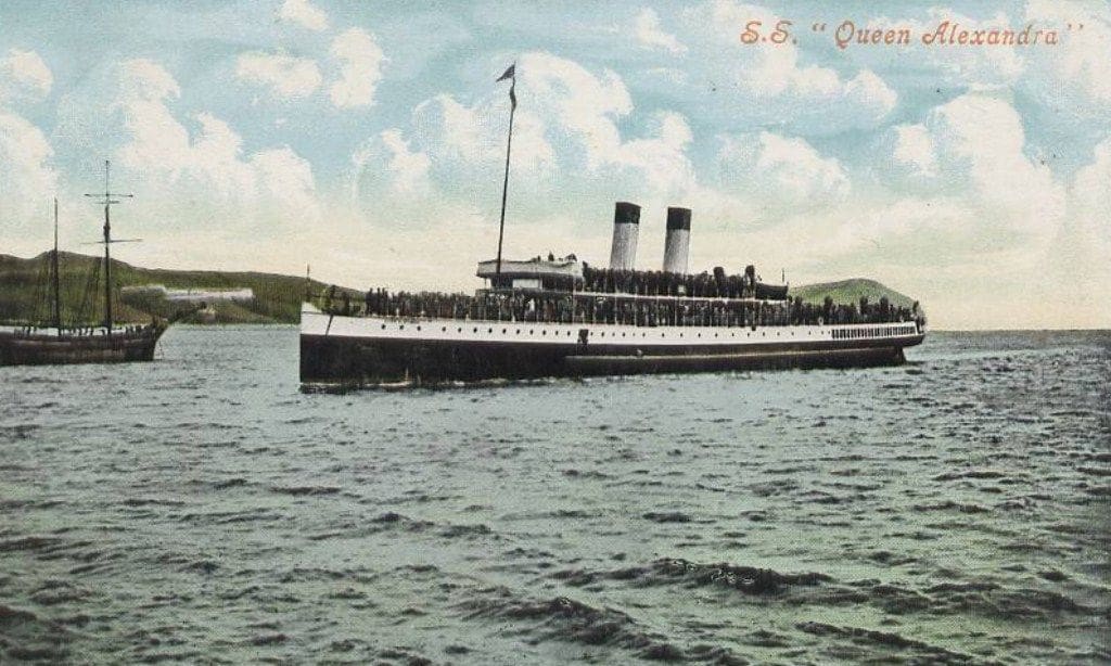
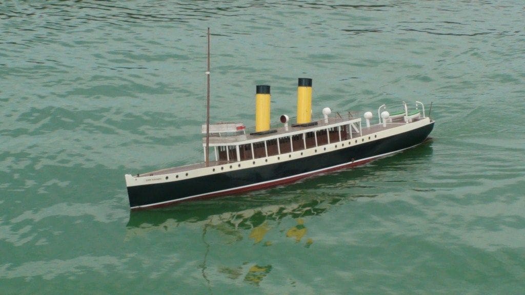
The 1901 turbine steamer King Edward (incidentally, the world’s first turbine passenger steamer) and her 1902 sister ship Queen Alexandra. Although both ships were turbine-powered and propelled by screws, they were both built by Denny’s of Dumbarton and the design was actually based on a modified paddle steamer hull design.
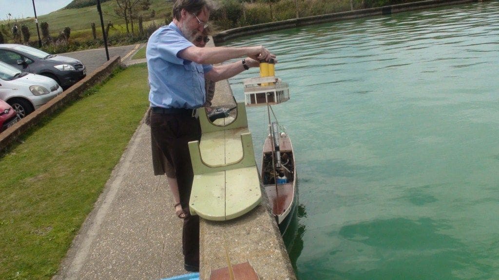
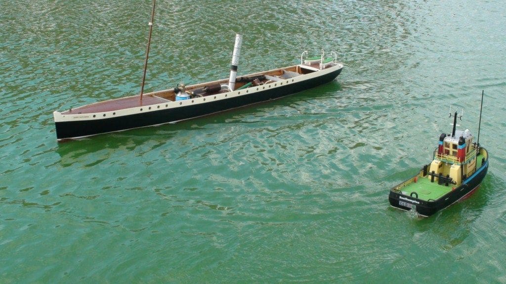
So, for no other reason than that I liked the name of Queen Alexandra, that it was to be, Photo 8. The original ships had three propeller shafts, but I decided to simplify matters by omitting the central shaft to arrive at a twin shaft arrangement as apart from anything else, accurately drilling a propeller shaft hole on the centre line in a completed hull is anything but straightforward.
Hull modifications
Studying drawings and photographs of the original vessels showed that I would need to add a 25mm (1 inch) extension to the top of the bulwarks as originally built and Photo 9 shows a part of that extension. The position of the waterline would definitely need to be raised, which is always useful with model steam boats, as it makes them sit lower in the water helping enormously with stability. These modifications were made to the hull and it was painted and fitted with a fixed forward deck.
Removable deck sections
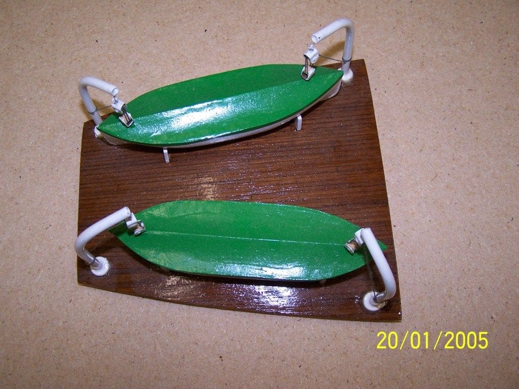
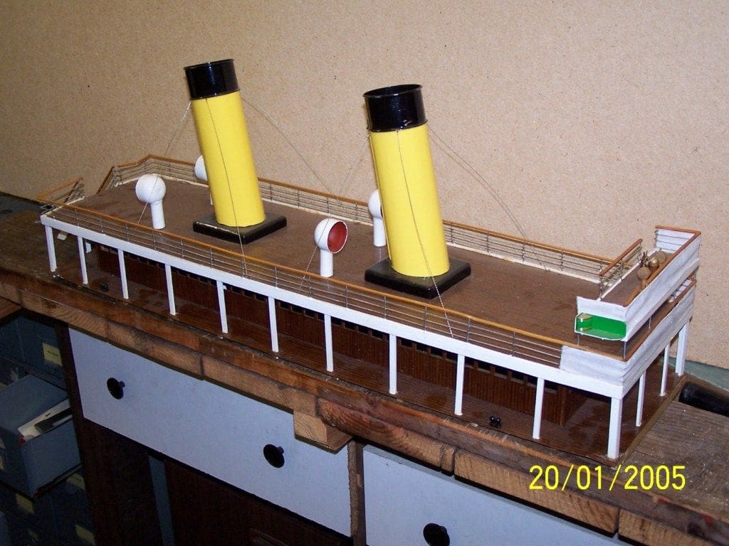
Four sections of deck were made removable to allow easy access to the steam plant, gas bottle and radio control equipment. These comprised a small deck cover above the tiller arm, an after section (fitted with the lifeboats) for access to the radio gear, a forward section (fitted with the mast) for access to the gas bottle and a midships section (comprising the complete cabin and upper deck) for access to the steam plant. Photos 10 and 11 show two of these sections. There was nothing remarkable about the work involved, but this did mean virtually unimpeded access to almost the whole of the inside of the hull.
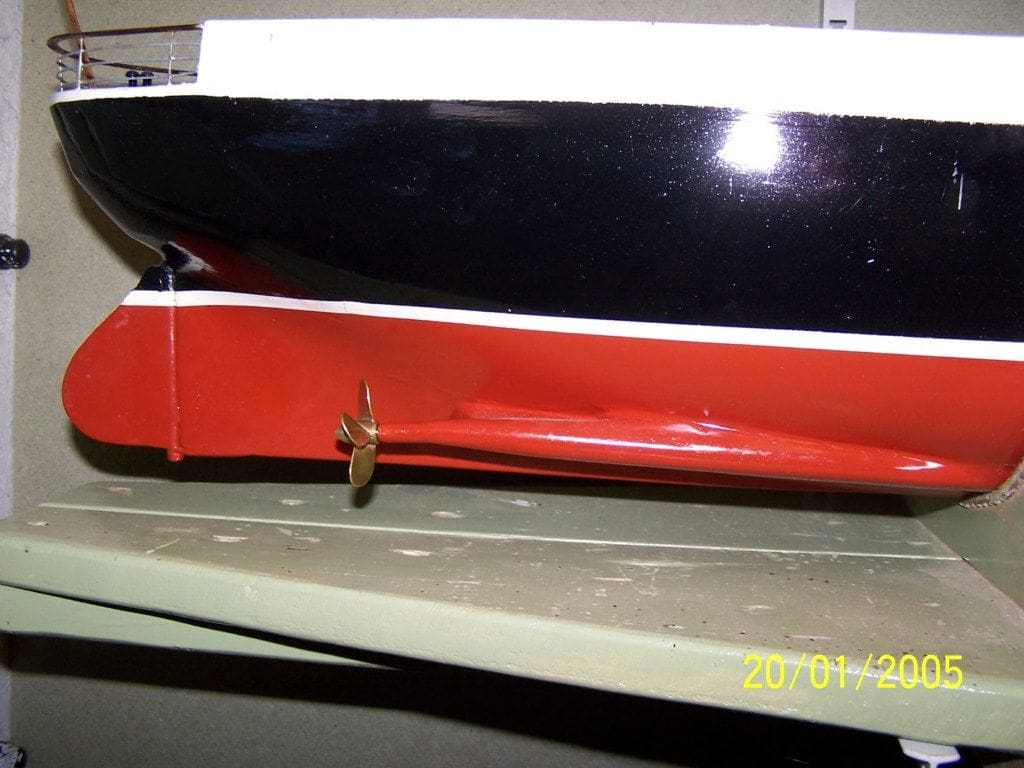
Propeller shafts
Openings were made in the hull and one of the after bulkheads for the two 16 inch home made propeller shafts and these were lined up correctly and fixed into the hull with the use of wooden fairings, car body filler and epoxy. Each was fitted with a handed 35mm diameter four blade propeller as in Photo 12. As an aside to this, the large ventilator cowls on the upper decks were made from the plastic shells from a children’s treat called a Kinder Egg which were just the right size. The ultimate in recycling I suppose!
More years passed….
By now, it was 2007 and Queen Alexandra had been around for ten years whilst I did other things (doesn’t time fly when you are having fun?) and I was becoming impatient to see her on the water. So, I cheated and fitted her with two MFA Como geared electric motors, a cheap and cheerful Chinese electronic speed controller and a pair of SLA 6v batteries connected in series to give 12v. Then the son-in-law and his van were pressed into service again to take Queenie (as she had become known) to the lake for trials. She sailed and performed magnificently after the lightest of light breezes had faded away, but in anything other than a flat calm she heeled sufficiently with the wind to almost cause me heart failure. Since the boiler was currently installed in the hull and the electrics had been added, I blamed the temporary battery installation for the heeling problem, but this would come back to haunt me later.
Brain wave!
Then came another flash of inspiration (or if you wish, insanity), which I was to regret. Since the original ships were turbine powered, why should I not use turbines in my model? Simple enough, I thought; a turbine just has a casing to house a wheel with teeth around the edge that you blow steam at to make it go round. Okay, it goes rather fast, but that can be taken care of using a reduction gearbox between the turbine and the propeller shaft.
So, I designed and built two near-identical turbines, one right-handed and one left-handed, each fitted with a gearbox having oil lubricated brass reduction gears. Both turbines were fitted with three steam jets, two for going ahead and the third (blowing on the wrong side of the turbine disc) for going astern. Tests of the individual turbines on compressed air were promising, with reasonable performance when going ahead and a very weak performance for astern, thus very much like the original ships. However, I found that a lid had to be made and fitted to the gearboxes to avoid getting an unwanted shower of lubricating oil.
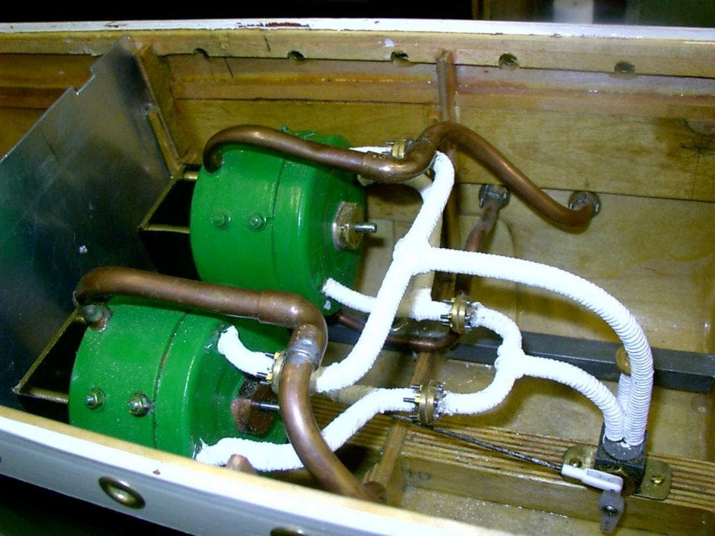
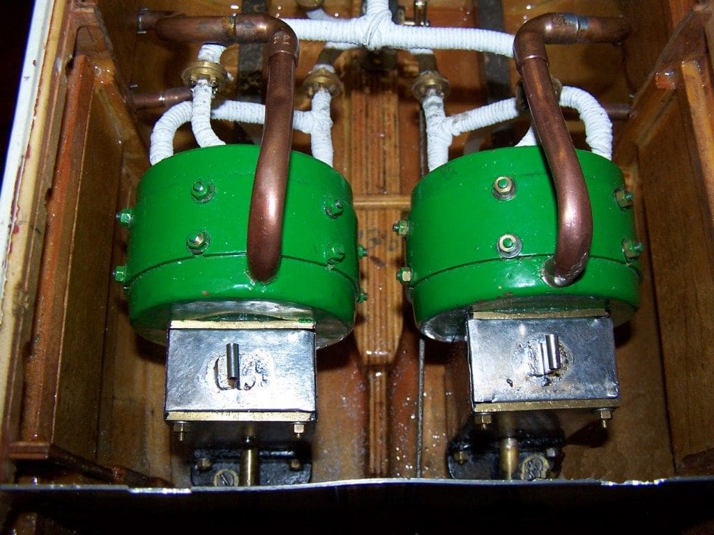
The next problem was how to control the turbine machinery for ahead, astern and variable speed. This was solved by the discovery of a redundant moped fuel tap in the scrap box. With a servo link in place of the tap handle, the steam inlet from the boiler connected to the old petrol outlet and the ahead and astern jets on the turbines piped to the original ‘flow’ and ‘reserve’ inlet connections, I had the basis of a working system. With the turbines, gearboxes, propeller shafts and control valve installed in the hull, Photos 13 and 14, the system was tested on compressed air and seemed to work.
The boiler originally built for use with the paddle engine had been fitted into the hull prior to its maiden voyage on temporary electric power so it was a simple job to pipe it to the control valve, fill it with water and fire up the complete steam plant on the bench. By this time, the boiler had been tried using a number of different firing methods with varying degrees of success:
Coal fired
This failed dismally as there was not enough depth of fire to keep the boiler steaming and the boiler could not be raised any higher owing to stability problems with the model.
Paraffin blowtorch
Another failure as the torch kept going out when aimed into the fire door and heat escaping around the torch boiled the water in the boiler water gauge.
Simple tubular gas burner
Worked fine on the bench, but tended to go out if there was any breeze.
Ceramic gas burner
After much experimentation, I arrived at a fully working design which took me around three years of trial and error.
So, once a check for satisfactory operation of the safety valve had been carried out, the engine stop valve was opened and the control valve set to full speed ahead. This proved exciting from one point of view and disappointing from another. The excitement came from the steam expelling all the oil from the turbine bearings looking a bit like mayonnaise, which was not readily apparent when running on air, and the disappointment from the boiler literally ‘running out of steam’ and being incapable of supplying the turbines.
Back to the drawing board
This time, a decision was made to build a conventional reciprocating steam engine that should be capable of running from the existing boiler. I elected to build a twin cylinder, double acting compound engine.
A twin-cylinder engine is essential if it is intended to control the speed and direction of rotation of the unit since a single-cylinder engine could come to rest at either top or bottom dead centre and then will not restart without assistance which is a major problem mid-pond! With a twin-cylinder engine, having the cranks orientated at 90 degrees to each other, the engine can stop at top or bottom dead centre on one cylinder but will always be able to restart on the other.
A double acting engine uses steam pressure alternately on the top and bottom of the piston, driving the piston in both directions, unlike a petrol or diesel engine where the piston is driven in one direction only.
A twin-cylinder compound engine has a small diameter high pressure (HP) cylinder and a larger diameter low pressure (LP) cylinder. The steam from the boiler passes into the HP cylinder where it expands and produces useful power by driving the piston and is then exhausted at a reduced pressure directly into the valve chest of the LP cylinder. In the LP cylinder the steam expands again to produce yet more power. So in effect the engine extracts as much energy as possible from the steam by using it twice. However, if the engine stops at top or bottom dead centre on the HP cylinder where that cylinder cannot start, there is no exhaust steam to power the LP cylinder either. This introduces a complication in the starting of a compound engine in that a system of steam valving is needed to route full boiler pressure to both cylinders at once (allowing the engine to start in any position) after which it can be selected to run as a compound. This valve is called the Simpling Valve.
Whilst compound engines were used in full-size practice to economise on fuel since they are much more efficient, there is no real advantage to compounding in model steam engines. However, it is more complex and I like a challenge!
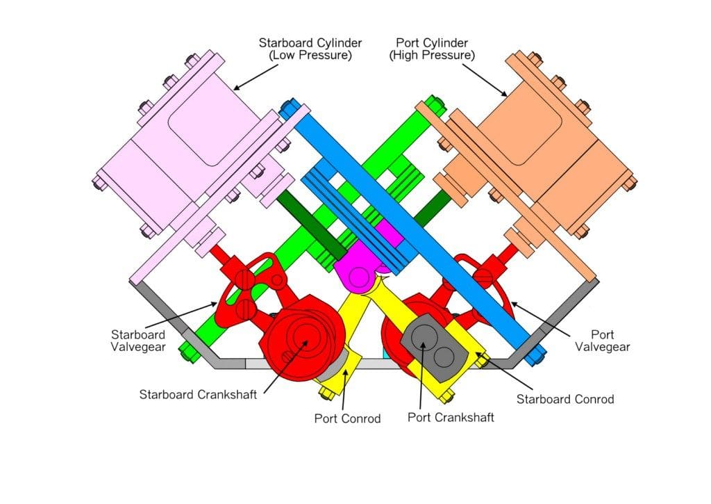
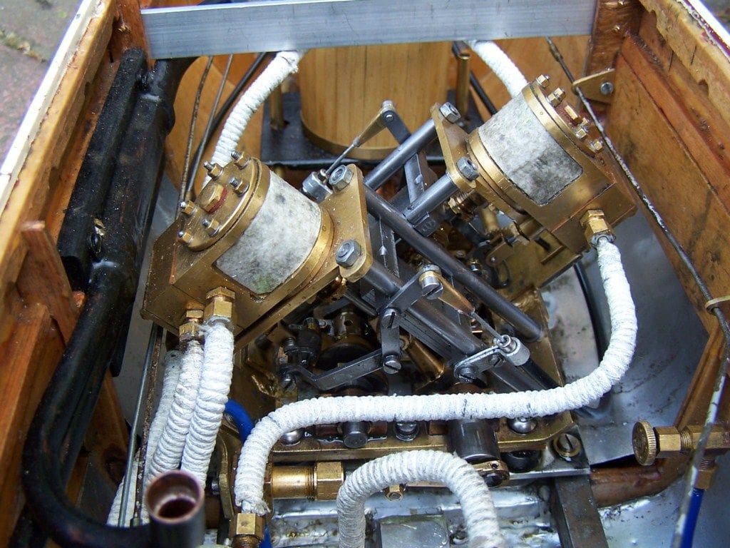
In order to keep the centre of gravity of the engine as low as possible, namely to avoid worsening the stability problems that I already had, it would need to be built in a vee-twin format. I also needed the engine to be capable of driving two propeller shafts in opposite directions. I found a sketch of a design to accomplish that in a reprint of a 1920 booklet entitled ‘Machinery for Model Steamers’ by Percival Marshall. This design had a separate crankshaft for each cylinder, the crankshafts being geared together to run at the same speed, but in opposite directions and with the valve gear for one cylinder driven from the second cylinder crankshaft and vice versa. Quite complicated, but as I said before, I like a challenge! Photo 15 shows an end elevation of my proposed engine design (please forgive the many colours, but it makes the drawing a little easier to follow) and Photo 16 shows the engine installed in the model. Again, this was not a matter of just a week’s work, so after a further six months toil at the lathe, milling machine and fitting bench, I finally had a working engine, simpling valve, lubricator and regulator valve installed in the model. It still needed final adjustments and running in as well as attention to any of the teething troubles that always seem to crop up at the lake side, but never ever whilst running on the bench of course!
The valve gear on this new engine followed full size practice in having slide valves operated by Stephenson Link motion. This motion has two eccentrics per cylinder (one for ahead rotation and a second for astern), with selection of which eccentric controls the engine rotation being through the medium of pivoted levers connected to a radio control servo. It will not surprise you, dear reader, to know that this arrangement was also to give me much grief a bit later.
Testing
The whole power plant appeared to work perfectly whilst running in on the bench, so the model was taken to the lake for yet another maiden voyage, but this time on steam power and yes, the son-in-law again did the honours again with transport.
There were quite a number of people present at the lake, which usually bodes ill for a test of a new steam model. I have learned from experience that the model always seems to develop faults in direct proportion to the size of the audience! So, sure enough, the reversing gear failed to work correctly at the lakeside. As a result, the model was put in the water and locked into ‘ahead’ only, with the hope that nothing would get in her way as at 15kg displacement she is a bit of a lump. Queen Alexandra steamed away from the lake side until when just out of reach, the model caught a light breeze and threatened to capsize, which was probably not as bad as it looked to me, but then continued around the lake at a very stately slow pace until running out of steam. Thus, once again, the boiler and burner combination could not keep pace with the engine’s steam demands.
Back to the drawing board again
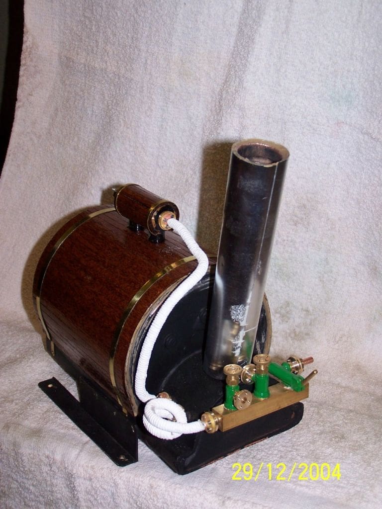
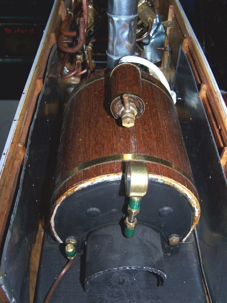
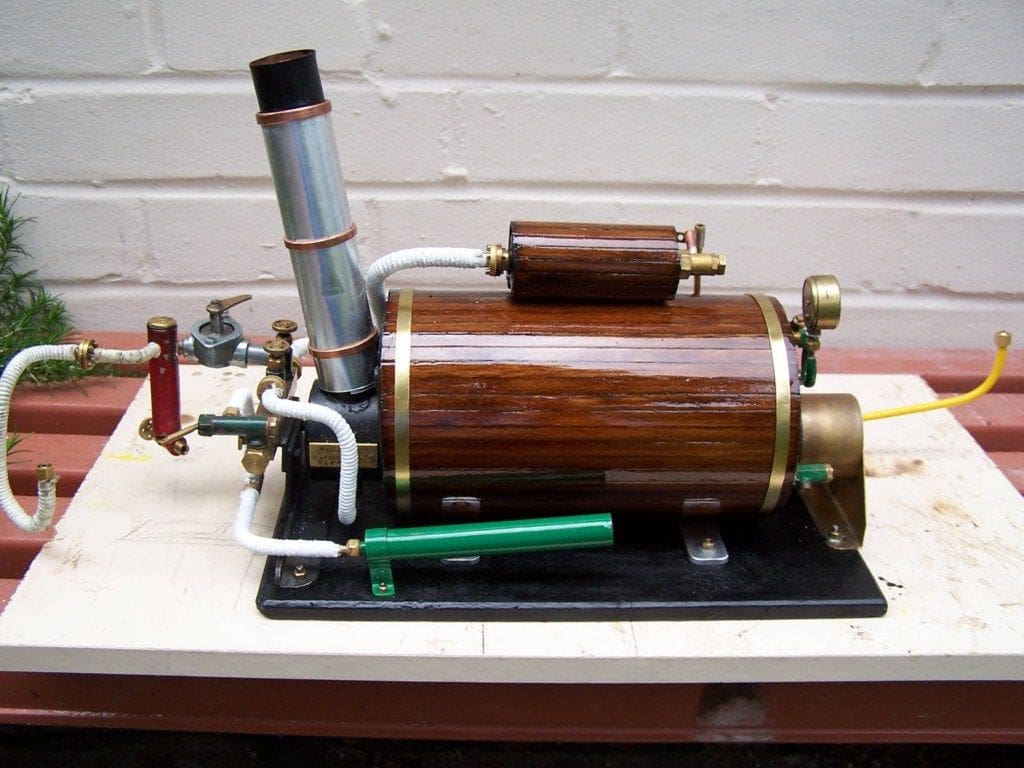
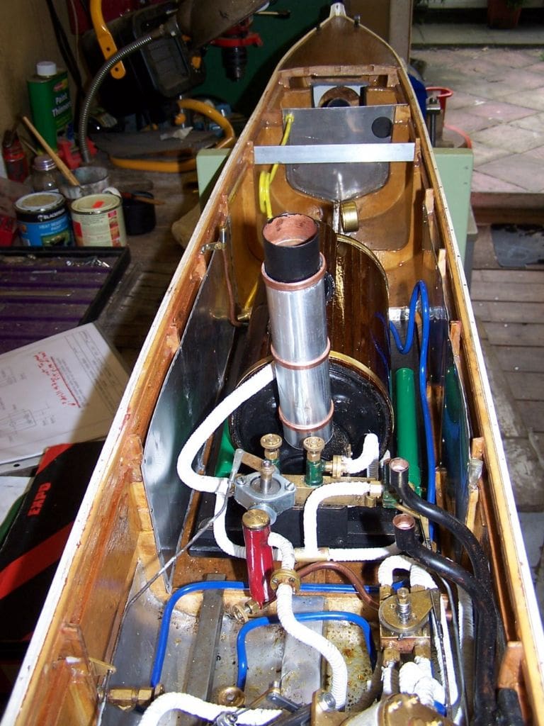
What with stability problems and the lack of steaming capacity, I almost felt like giving up, but made a decision to design and build yet another boiler and to retain the engine unit, so back to the drawing board yet again! The old boiler was removed and replaced with a horizontal boiler with a much lower centre of gravity and only half the weight, being 2.25kg instead of 4.5kg when in working order. Photo 17 shows the completed boiler and Photo 18 shows it installed in the hull and piped up ready to go. Yes, this was another six month’s work!
As the model had floated at around the correct waterline with the old heavy boiler installed, I was able to add 2.25kg of ballast very low down in the hull and below the waterline, where it was sorely needed to restore some semblance of stability. I use old lead water pipe as ballast flattened in a vice and fixed in place with silicone sealant.
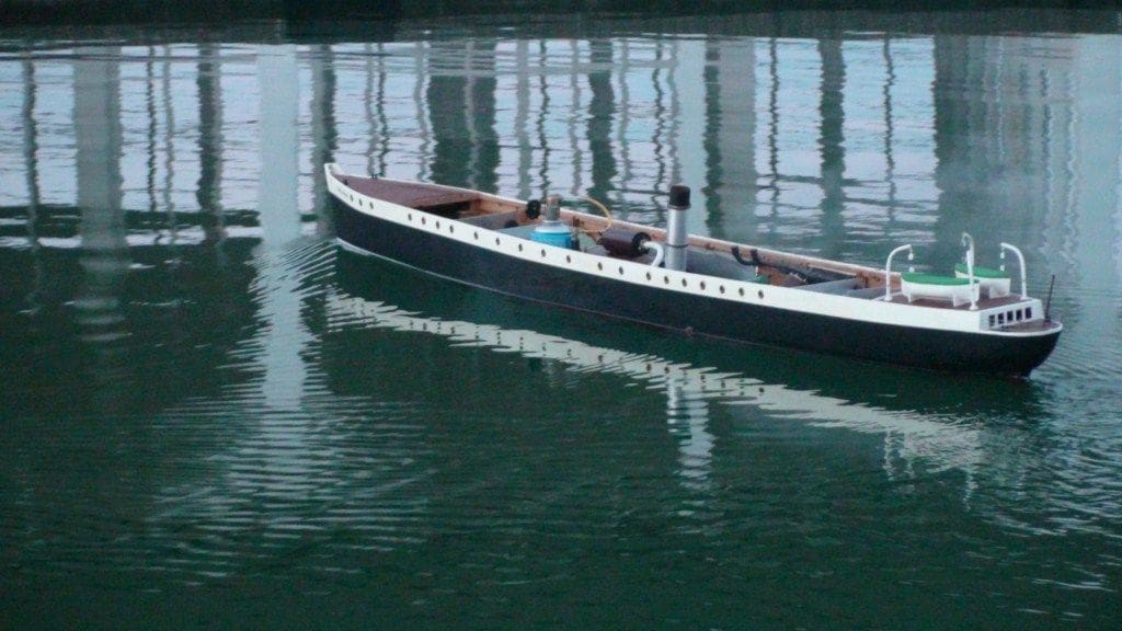
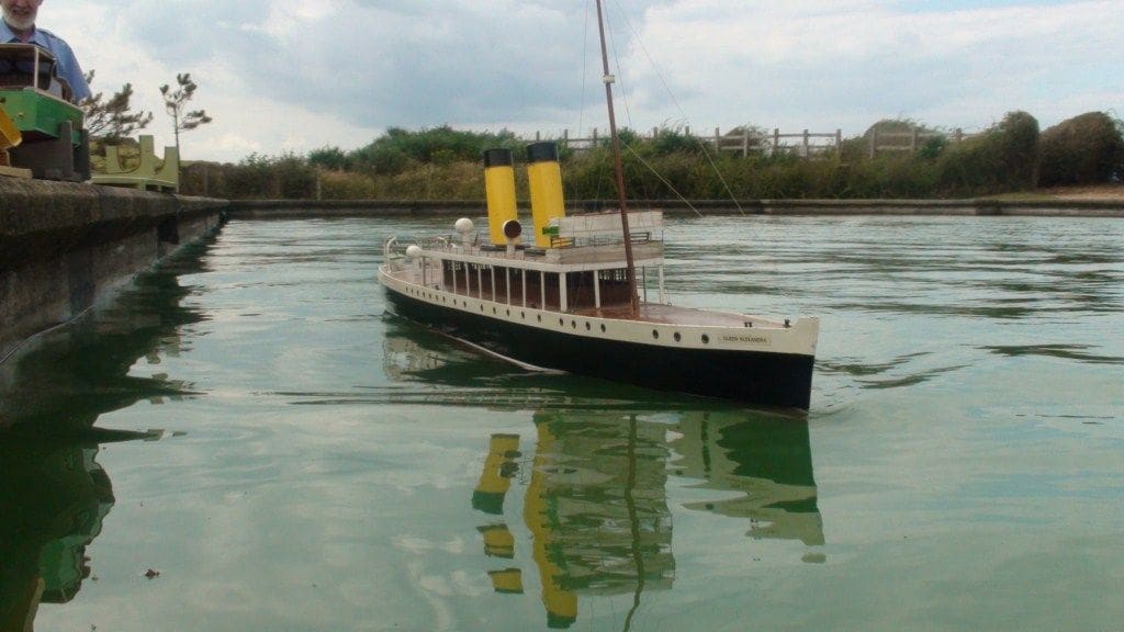
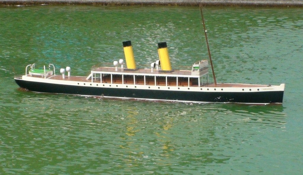
Following further bench testing, the son-in-law came to visit again in November 2010, now with a people carrier vehicle and lots of room, so we again visited the lake at Sheringham. This time, the audience was tiny, which could have been down to the temperature being around freezing, and Queenie as I now liked to call her, voiced her objections to being woken up with a fractured gas supply pipe! After cobbling up a temporary repair with a length of silicone tubing and some wire (to keep the tubing in place), the boiler was fired up, correct radio control operation confirmed, steam pressure raised, safety valve checked and the model minus superstructure placed in the water. She steamed beautifully, running at around scale speed and responding to all controls more or less as she was supposed to, including the remote controlled steam whistle. With the exception of an easily corrected slight list to port, probably caused by the gas bottle being out of position on the temporary pipe, she behaved at long last as a true Queen, Photo 19.
More problems!
Another minor niggle manifested itself in that the engine reversing gear only worked when it wanted to and not when required, resulting in a full stop of the engine until it could be given a flick in the required direction which is not that practical in mid-lake! Later tests on the bench showed that this was a result of a poorly adjusted linkage from the reversing servo such that one cylinder reversed slightly before the other and locked the engine, thus one cylinder was trying to go ahead and the other astern. This was easily corrected by more detailed attention to the setting up of the reversing linkage so that both cylinders changed direction at the same time.
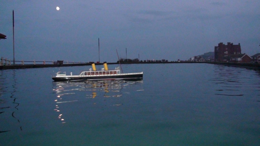
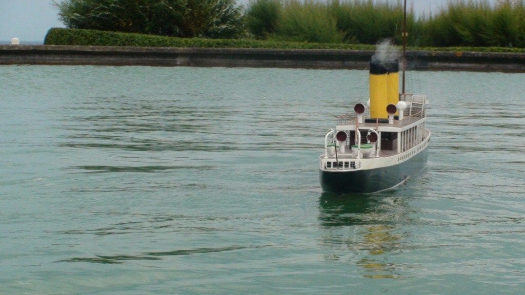
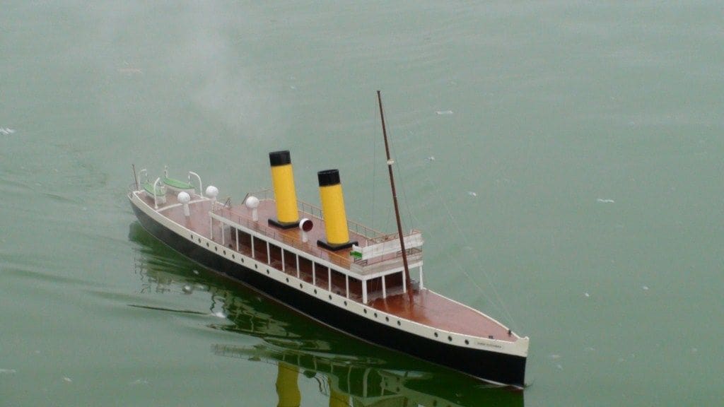
A further run was carried out with all of the superstructure fitted with equally satisfying results until the servo controlling the steam regulator failed in mid-lake with the engine stopped, resulting in steam everywhere when the safety valve lifted. Once the model had been recovered, the regulator was fixed in the fully open position and steamed until it became rather too dark to see what was going on as it did not have lights, Photo 20. The servo failure was due to a very stiff regulator, now corrected.
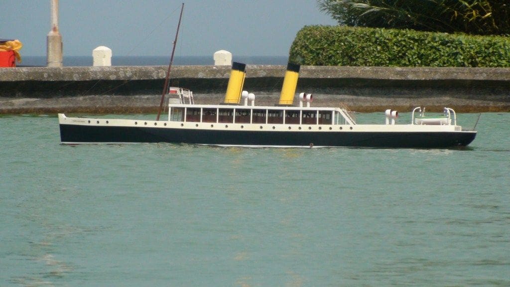
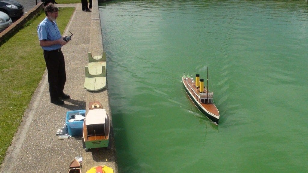
After some minor adjustments and the building of a slightly bigger ceramic gas burner, the model was returned to the Sheringham boating lake in July 2011, where she steamed beautifully and did everything that I asked of her, including going ahead and astern when required, and all of this in spite of the presence of a large audience.
One member of that audience was a young boy aged about five, who was absolutely fascinated by Queenie and followed her around the lake. At one point he was caught on video saying, ‘That’s so amazing! I’ve never seen a proper steam sailing boat on a boating lake before’! So who knows, perhaps I have managed to create a convert to our hobby?
Conclusion
Finally, after all these years of toil in design and construction, redesign, reconstruction, and all more than once, I have a model that is most impressive both on and off the water and which proves the old adage, ‘If at first you don’t succeed, then try and try again’. I now have the incentive to get on and finish the final details of Queenie, although I think that I would rather sail her now that she actually works. There is a short video of the model on YouTube. Please simply enter ‘steamship Queen Alexandra’ into the search box.
(A remarkable story of perseverance and determination over such a lengthy period, for which Phil is to be commended. No doubt he will find a use for his steam turbines? – Editor)


