Gareth Jones rebuilds an Elco 80 foot patrol torpedo boat
Introduction
I have always enjoyed practical hobbies and one day I said to my wife; ‘I fancy building a model boat’! This was just a passing thought, but in the back of my mind was the idea of building a large scale radio controlled tug with lots of detail and possibly some working features. The following Christmas after several hints, I did not get a large cardboard box with a kit of parts but instead I opened my presents and found a copy of the Tug Boat Book and a 1:24 scale plan of a TID tug. Progress was very slow as I was restricted to building on the kitchen table but after a few years my prayers were answered and this time my wife really came up with the goods as she bought me a shed! Construction progressed more quickly, albeit with some diversions into radio controlled aircraft and cars, but by early 2008 the tug was completed and successfully sailed in the local canal lock.
Enjoy more Model Boats Magazine reading in the monthly magazine.
Click here to subscribe & save.
The TID took pride of place in our dining room and one day a friend of my wife was admiring it and said; ‘We have a big grey model boat in our loft. Our next door neighbour gave it to us about 20 years ago and the kids are too old to play with it now, so do you want it?’ Not knowing what to expect I said yes, largely out of curiosity, rather than thinking it might form the basis of my next boat building project.
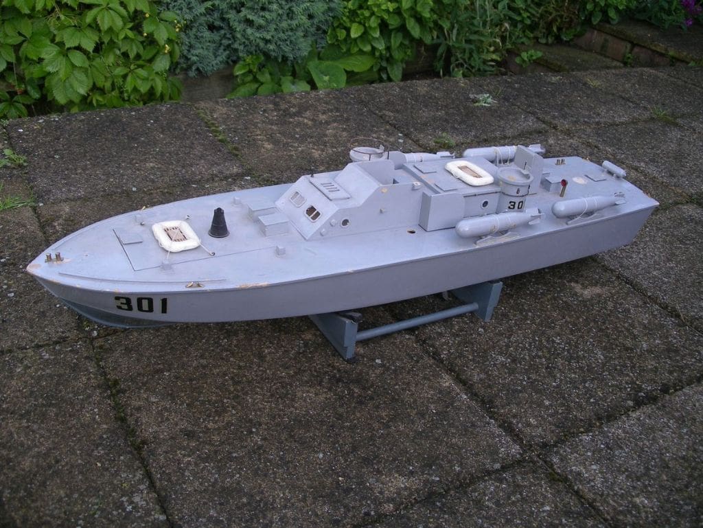
A few days later the boat arrived, Photo 1. The basic hull and superstructure were originally quite well made but looked rather simplistic. It was 40 inches long, had four torpedoes, a couple of machine gun turrets but was pretty battered and the rest of the armament was missing or damaged. It had a single, rather odd looking electric motor but no sign of any radio control, Photo 2. Judging by the internal construction and remaining wiring it had probably been powered by a couple of ‘bell batteries’ and older readers may remember these rectangular dry cell batteries with brass screw terminals. The internal bulkheads were identified with printed numbers so I guessed it had originally been a kit rather than scratch built and I subsequently saw a similar model at the International Model Boat Show at Warwick with a label identifying it as a KeilKraft kit.
The Elco PT boat
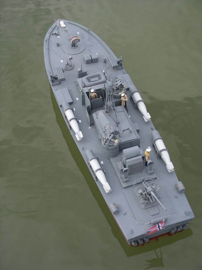
The distinctive forward raked machine gun turrets made it easy to identify on the internet and it quickly became apparent that I had been given a 1:24 scale Elco 80ft patrol torpedo boat. There is a wealth of information available about these craft and it is clear that there is a large following of enthusiasts for them even today. In July 1941 the US Government held a competition to decide who would receive a contract to supply fast, heavily armed patrol boats to the US Navy. A number of manufacturers competed in the evaluation which started from the New York harbour area and included a 190 mile full throttle run out at sea which became known as the ‘plywood derby’! Elco won the lion’s share of the business, with smaller orders going to Huckins and Higgins.
Around 400 Elco PT boats were built between 1941 and 1945. They had an 80 foot long wooden hull with two diagonal layers of one inch thick mahogany planks with a glue impregnated canvas core sandwiched between them over conventional framing. Powered by three 1500hp Packard petrol engines they had a top speed of over 40 knots. PT boats carried a variety of weapons including torpedoes, guns, rocket launchers and depth charges, making them pound for pound the most heavily armed vessels of the US Navy in World War Two. They had an illustrious operational career, particularly in operations against the Japanese in the Pacific and several films and TV series have featured them. The most famous vessel is probably PT 109, which was commanded by John F. Kennedy who went on to become the President of the USA.
Searching the internet reveals that there are some pretty impressive models of Elco PT boats. An excellent example is the 1:16 scale model of PT 588 made by Alan J. Zulberti which is described in detail at: http://www.dallee.com/PDFs/PT-588%20Article.pdf. In addition to the propulsion, lights and sound systems it has working roll off racks and torpedoes, a smoke screen generator, a working 37 mm deck gun which fires 3mm rounds, an onboard video camera and deployable life raft. Definitely something to aim for!
While I did not plan to surpass Mr. Zulberti, I resolved to carry out an upgrade to the model I had been given by fitting radio control, three powered propellers and rudders, engineer some of the guns to rotate and fit working lights. After some further research I decided to base the model on one of the later production variants which could be fitted with a rotating radar scanner and the widest variety of weapons. The project therefore would have four major aspects, refurbishing the hull, a complete new superstructure, new propulsion system and the weapons.
Refurbishing the hull
While researching Elco PT boats, I discovered that John Haynes produced a detailed 1:24 scale model kit similar to the standard of boat that I wished to build. I wrote and asked if he would be prepared to sell me just the drawing for his kit and some of the weapons and fittings. I awaited a response with some trepidation as it seemed a bit cheeky and I have heard that some kit suppliers are very much of an all or nothing mind set. In fact, John was very helpful and after an exchange of emails and the associated funds, I quickly received the drawing and a very high quality set of white metal and resin parts to make the weapons.
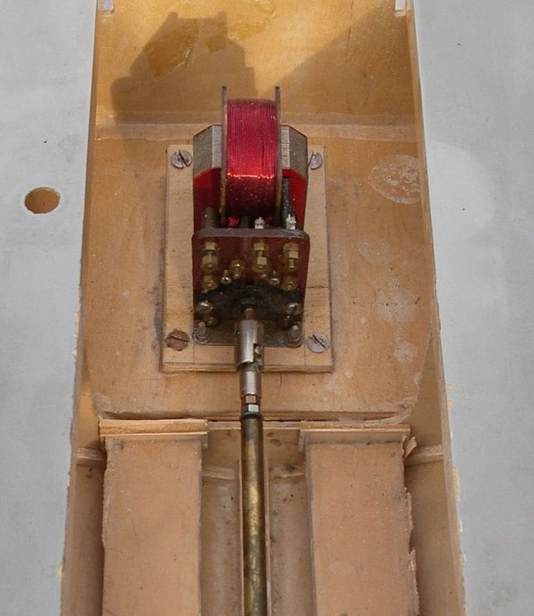
Before removing the existing, rather strange looking electric motor, I decided to test it to see if it still worked. It was connected to the propshaft by a rather battered universal joint and had two wires which ran to a hole in the deck where I guess there had originally been a switch. I connected up a receiver, electronic speed controller, and 7.2v NiCd battery pack to the motor with no switch or fuse to save time. I turned on the transmitter and speed controller and gingerly advanced the throttle forward. The motor sprang into life and while it was very noisy, primarily because of the sloppy universal joint, it worked, so my next step was to try reverse.
At this point my enthusiasm to see what happened overcame my lifetime of systems engineer’s training. At work I had always impressed upon my younger colleagues; ‘Make sure you understand exactly how something works before you start b*******g about with it’ and unfortunately I didn’t! Pulling back the throttle lever meant nothing happened. By the time the throttle was at full reverse my nose told me something was wrong. The speed controller was melting before my eyes and giving off acrid smoke, which after disconnecting the battery forced a hasty evacuation of the shed. In disgust, largely at my own lack of common sense, I dispatched the motor and speed controller into the round filing cabinet on the floor. Subsequently, in a recent edition of Model Boats magazine I realised when reading one of David Wiggins’ articles, that I had probably binned a very collectible vintage Taycol motor. Well, I still have the picture anyway!
The basic hull was reasonably sound and had a long open section in the deck where the two piece superstructure fitted. I decided that the forward part of this opening, about 6 inches in length, should be permanently covered as this would give me a clean tidy deck finish with no unsightly joint lines. Before fitting a ply plate, blocks of polystyrene were fitted into the compartment to provide buoyancy. This left me with an 18 inch long compartment for the propulsion system in the centre of the boat and 6 inches at the aft end for the rudder controls, r/c and any switches.
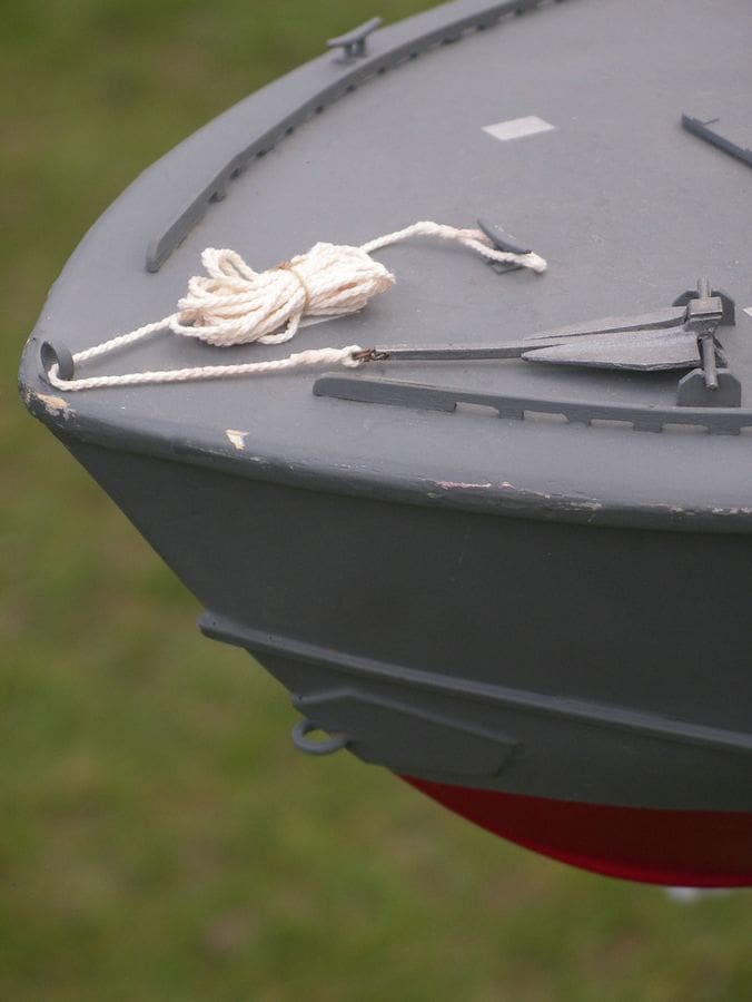
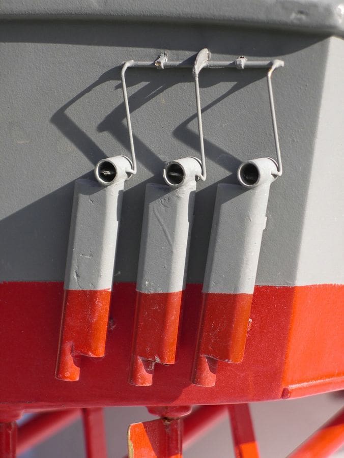
I added spray strips to the hull sides using 3/32 inch square spruce. The towing eye and support plate, Photo 3, were made from a steel spring washer and a piece of brass sheet bonded to the hull with epoxy resin adhesive. The two sets of three engine exhausts fitted to the transom were a notable feature of Elco PT boats, Photo 4. Each had a mechanically operated two-way valve which at high power allowed the exhaust to vent directly aft for minimum power loss but with the penalty of high noise levels. At low power, the valves directed the flow down through silencers and the exhaust gases exited underwater. The additional back pressure reduced available engine power but also significantly reduced noise to allow stealthy operation. The exhaust valves were made from short lengths of 6mm brass tubing with brass wire bent to simulate the operating linkage. The silencer boxes were each made from two pieces of 6mm aluminium tubing glued together and filled with Milliput modelling putty to form the correct shape.
The new superstructure
Construction of the superstructure was relatively straightforward. The lower framework is essentially a ladder built up from 5mm x 25mm section pine. The lower half of this ladder engages in the main cut out in the hull covering the motor and battery compartment. The superstructure is built up on the upper half of the ladder using ply and strip timber to form the required shapes, Photo 5. Internal and navigation lights were fitted and the wiring run to a connector at the aft end. The windows were made from 2mm Perspex sheet. I have never mastered the art of gluing windows into the structure as I always end up with glue on the windows themselves. Instead I cut the correct sized holes squarely through the superstructure and if required make up a frame of thin card. The window itself is then cut slightly oversize and then trimmed to size using a power file to chamfer the edges so that they form a slight taper. By trial fitting them it is possible to achieve a neat tight fit without the need for adhesive. The superstructure can be painted without needing to mask the transparency and the windows are just pressed in tightly afterwards.
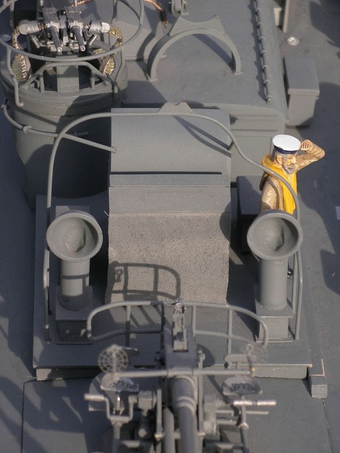
The handrails along the cabin roof and gun turrets were made from brass rod supported in suitable sized split pins which locate in holes drilled through the structure. The instrument panel detail was found on an excellent website: www.pt-boat.com, which has a wealth of useful information. For a while I tried without success, to find a suitable ship’s boat to fit on top of the cabin and in the end made my own from thin sheet ply. Since no internal details are visible this was quite easy and the end result is quite realistic, Photo 6.
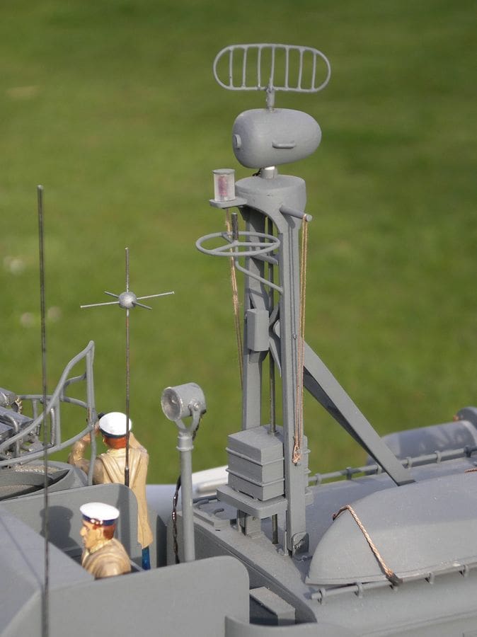
The radar mast was built up to the required size from thin strips of ply, Photo 7. The fixed radome was made from a bock of balsa which was drilled to allow a short length of dowel to be glued into it. This dowel was then held in a pillar drill chuck and the balsa was sanded to the correct profile. When finished, the protruding length of dowel was cut off. The rotating radar antenna was made up from brass wire soldered together flat for ease of assembly and then gently bent around a cylindrical former (a glass jam jar), to produce the correct curved shape. The drive motor is a small electric motor with a 500:1 gearbox mounted inside the cabin. The connection between motor and antenna is a thin brass rod, linked at each end by a short length of push fit plastic tubing. Although the original radar mast could be folded back onto a support frame to allow the boat to pass under low bridges, this is not possible on the model because of the drive shaft.
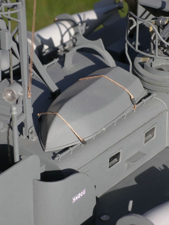
The other parts of the superstructure including the engine air intake and Bofors gun ammunition rack were built up from sheet ply. The fabric cover over the ammunition rack, Photo 8 was made from a piece of an ancient handkerchief which had naturally reached a scale like flexibility and even before painting was pretty close to the required grey colour.
The propulsion system
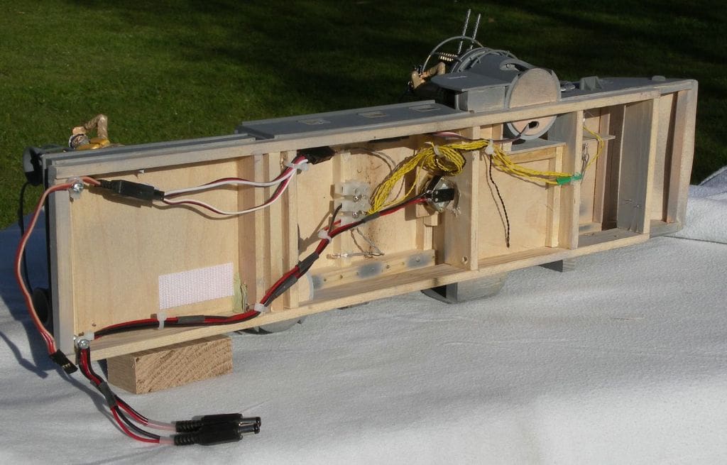
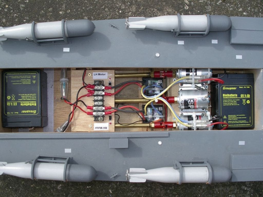
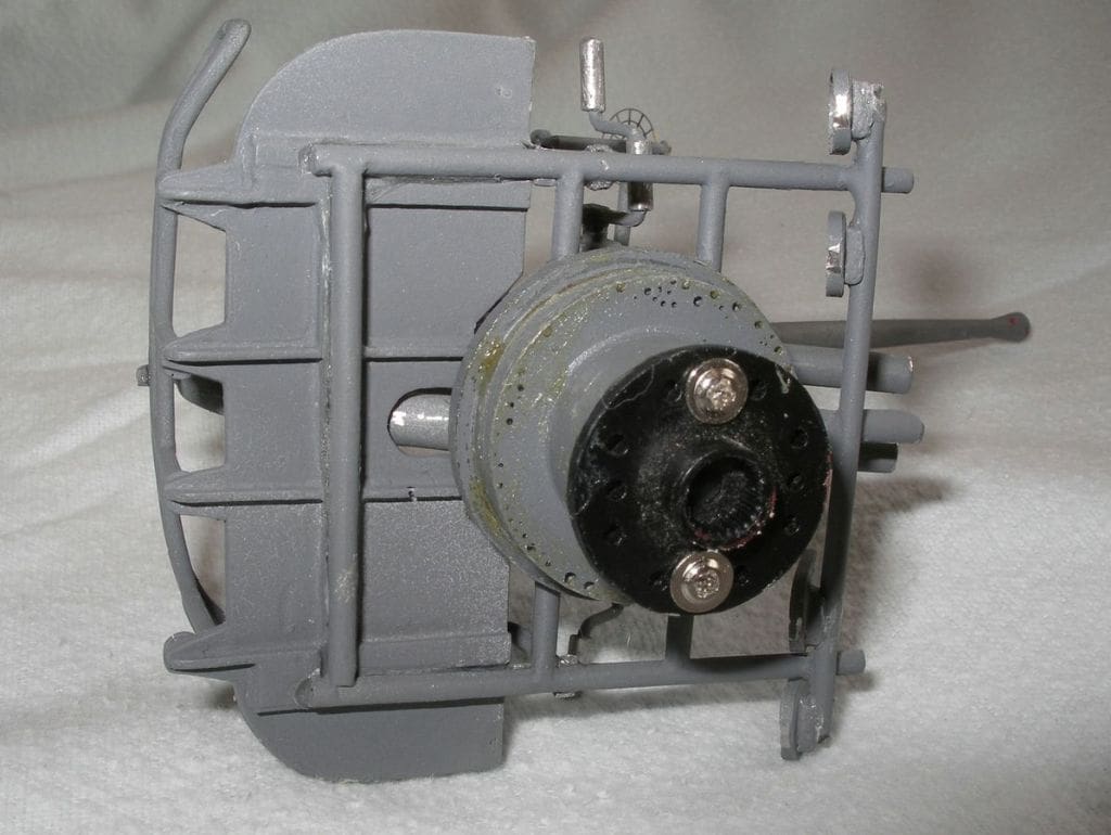
The nearest scale propeller size was 30mm and based on my earlier experience with the TID tug I decided to use three MFA 457-RE540/1 motors. These would have a direct drive to the propellers rather than 6:1 gearing to a 70 mm propeller as in the tug. At this stage my inexperience was starting to show as I did not really know if this would be a good match of battery voltage, motor and prop size. However, I did know that it would fit the space available. I decided to conduct a few tests in the bath in order to try and work out the optimum layout and weight distribution and eventually decided on two 6v, 4ah, lead acid batteries connected in series to give 12v, with one battery at each end of the centre compartment. The original internal layout of the propulsion system was not photographed at the time but to illustrate this article a mock up was created by adapting the current standard, Photo 9.
Radio control
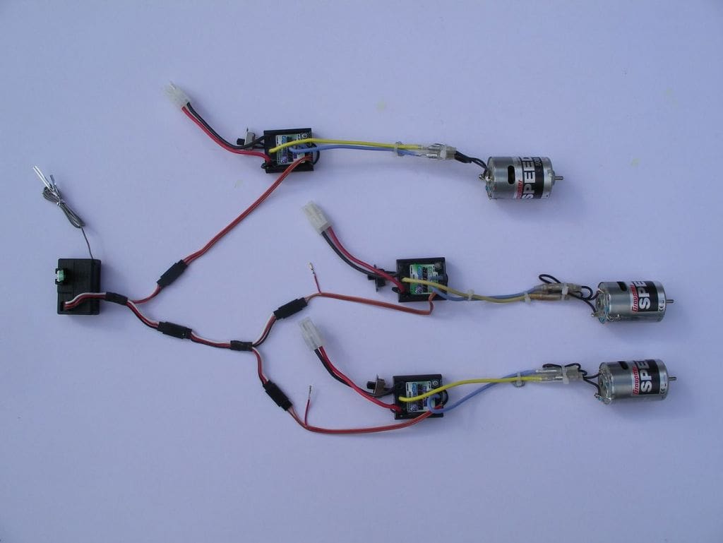
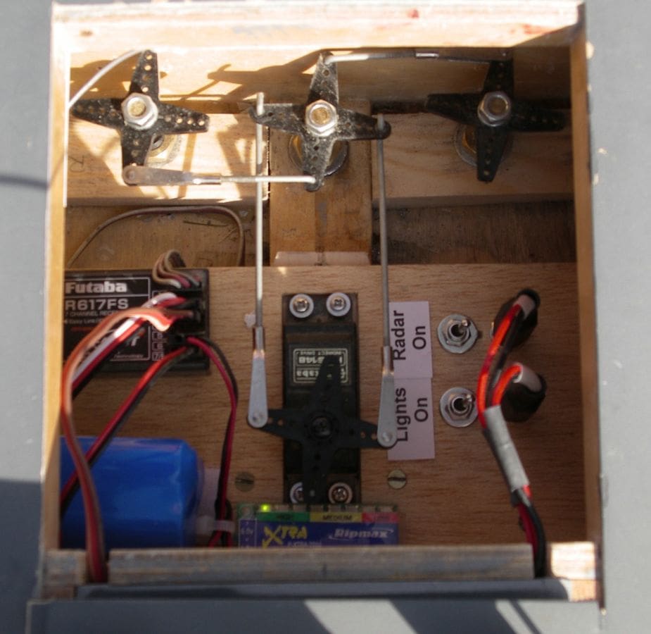
Initially I was planning to drive all three motors from a single speed controller but I had in mind the possibility of using a mixer unit at some stage in the future so I decided to fit three electronic speed controllers. These were connected to the receiver by a pair of Y leads, daisy chained together. The battery eliminator circuit of one speed controller, the uppermost one in Photo 10, was used to supply the receiver with power. The positive wires from the remaining two controllers were disconnected, as per the manufacturer’s recommendation. The detail of this set up is difficult to photograph in the boat so for the purpose of this article it was simulated externally as in the picture.
Testing
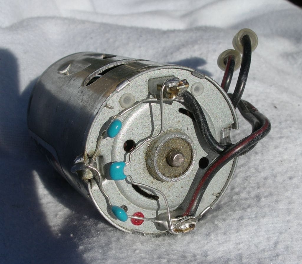
At this point things seemed to be going well, but when it came to the first test of the completed propulsion system it became clear there was a major problem. When run forwards at high power the motors would hesitate at random. This did not seem to be a simple power interruption but was a very rapid snatch down, accompanied by some large blue sparks in the motor concerned. If the motors were run in reverse everything was fine. All three motors had been suppressed with capacitors across the two terminals and to the motor case, Photo 11, as is standard practice.
As a first attempt at fixing the problem I tried an alternative motor which I had in my spares box. By comparison with the motors fitted it was a higher power buggy motor and it ran perfectly. After discussions with the motor and speed controller suppliers I was no nearer finding a solution and decided anyway to take the hull for a trial in the local pond. Testing showed that with all three motors running, the partially complete PT boat was disappointingly slow. Disconnecting the centre motor and running on just the two outer ones seemed to give a similar mediocre performance and the motors still ‘snatched down’ at frequent intervals.
There followed a whole series of trials on the bench to try and eliminate the ‘snatching’ fault. I suspected it was a motor control issue with perhaps some sort of interaction through the signal lines from the receiver to the speed controllers. One test was to try running the receiver from a separate battery and not using the speed controller BEC supply. Another was wrapping the signal lines in aluminium foil to screen them and using a W tail mixer to signal the three speed controllers. An alternative set of motors, in this case Graupner Speed 500E 12 V motors were tested but none of these changes made much difference.
More changes……
This was getting pretty frustrating, not to mention expensive, so a different approach was trialled. Testing on the pond had showed that the boat was too slow and too heavy, so the two 6v lead acid batteries were swopped for a pair of 7.2v NiCd packs. These were connected in series to give 14.4v and power just two of the Graupner Speed 500E motors. This gave a much better performance, the boat was about 1kg lighter and noticeably faster, but the motors got too hot to touch after a period of high power operation.
The next logical step was to fit larger and more powerful motors, better matched to the battery voltage and propeller size. The chosen combination now was pair of Graupner Speed 600E 7.2v motors, each supplied from its own speed controller and 7.2v battery. This combination worked well, the speed was good, the ‘snatching’ eliminated and the final solution in sight.
Final modifications?
The remaining changes made to the propulsion system were relatively simple. With just the two outer propellers driven and the W tail mixer in circuit, handling at low speed was excellent. In this configuration rudder and throttle lines from the receiver both go into the mixer. With pure throttle movements forward and reverse, both motors operate together. If rudder is applied with some throttle, the rudder servo works as normal but the motor on the outside of the turn increases in speed and that on the inside decreases. With the throttle neutral and just rudder applied, the boat would turn almost in its own length with one motor going forwards, the other backwards.
Problems again…….
However there were two disadvantages with the system, one major and one minor. Firstly if a turn was initiated at high speed the boat slowed down markedly, which was irritating and just looked plain wrong, particularly as the boat speeded up again after the turn. The propeller on the inside of the turn was being told to slow down by the mixer and to maintain the speed, but the propeller on the outside was being told to speed up, but it could not go any faster because it was already at full throttle and so overall, the boat slowed down. The second disadvantage was that if rudder trim was applied on the transmitter, it also affected the throttle and with the throttle lever neutral the two motors could be operating slowly in opposite directions. Directional trim therefore had to be applied by setting the rudder trim to neutral and then adjusting the rudder linkage in stages by trial and error, Photo 12. In practice with three rudders the boat steering was good enough and I eventually relegated the W tail mixer to the spares box to await a more suitable application.
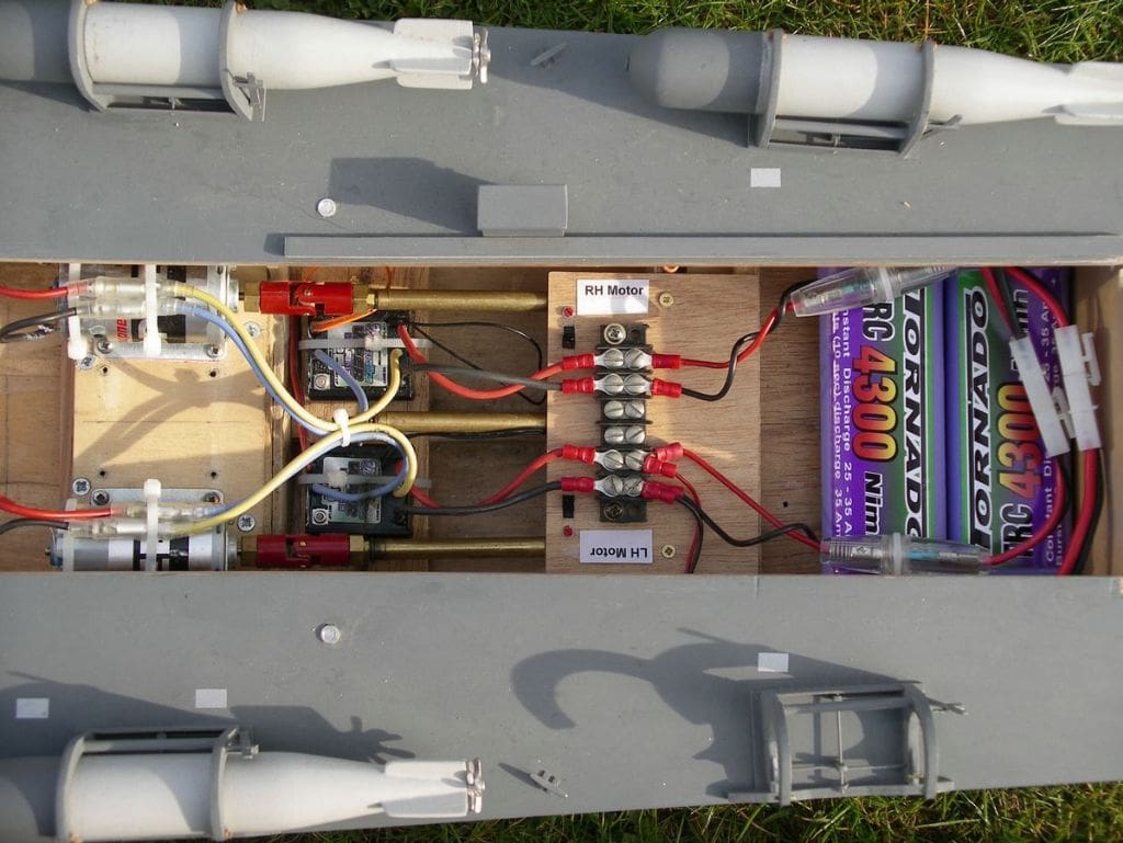
So, the final main battery configuration was a pair of 7.2v 4.3Ah NiMh batteries, one for each motor, Photo 13. However after about 20 minutes of sailing including quite a lot of high speed running, the battery voltage would drop to the point where the receiver failed to operate and the speed controllers began to behave erratically. A dedicated 4.8v receiver battery eliminated the problem and a battery voltage indicator (which can be just seen in Photo 12) was fitted to give a quick confidence check.
Development of the propulsion system was interesting and challenging but also frustrating and expensive. The cause of the motor snatching was never discovered but is now a thing of the past. Some overall performance measurements make an interesting comparison. In its original configuration with three motors and two 6v lead acid batteries the boat weighed 6.5kg and the power into each of the motors, with the propellers in the water was approximately 50 watts giving 150 watts in total. In the final configuration the boat weight had been reduced to 5.5 kg and the power into each of the two motors had been increased to approximately 135 watts giving 270 watts in total and transforming the performance.
Weapons – torpedoes
I re-used the bodies of the original torpedoes which came with the model from our family friend. However they were rubbed down and repainted and fitted with a pair of correctly shaped contra-rotating propellers from John Haynes. The roll-off racks were made from scratch with the operating linkage simulated by brass rod, Photo 14. I am not too fussy that a model is historically correct in every detail but I do like it to look as though it would actually work in practice. For a while I toyed with the idea of making up a working roll-off rack mechanism but eventually decided this could perhaps be an option in future. Several of the large PT boat models which have been built have had servo operated roll-off racks and torpedoes but it is not easy to do at 1:24 scale.

Guns
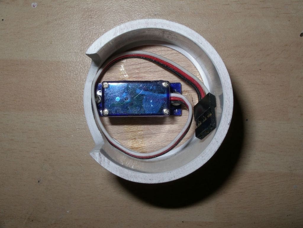
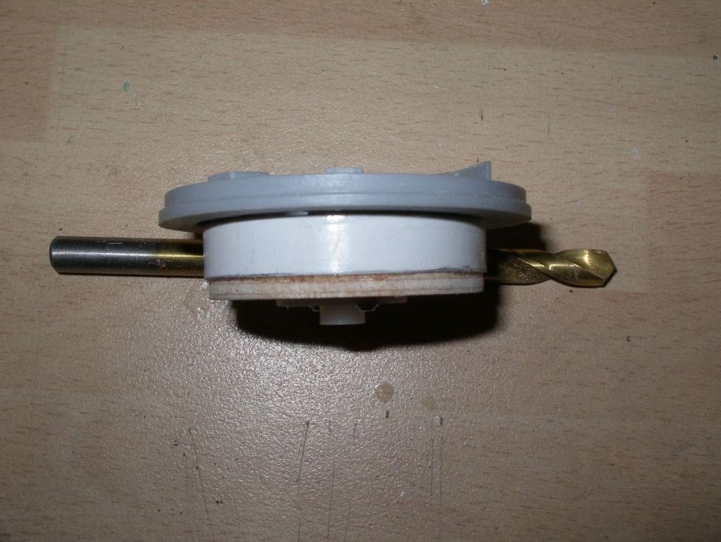
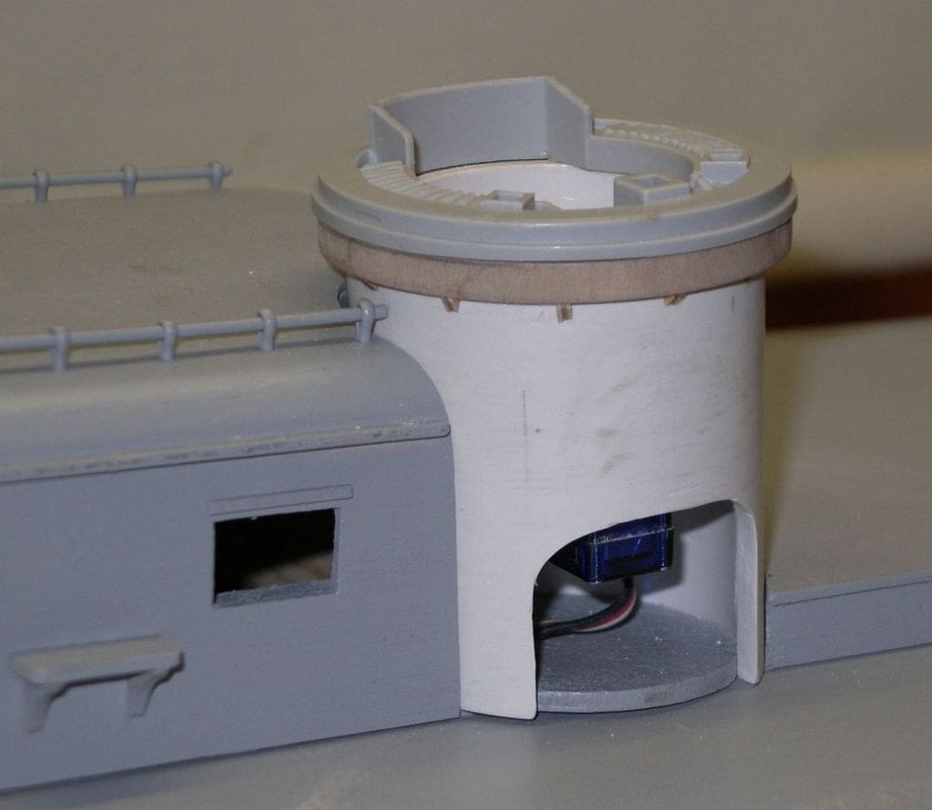
The forward mounted 37 mm cannon, the 20 mm Oerlikon cannon and 5 inch rocket launchers were built from kits supplied by John Haynes, Photo 15. All the items that he supplied were of excellent quality, fitted together well and really looked good. In addition, the quality of service was high with quick responses to emails and questions, short delivery times and overall a very helpful attitude. The two forward raked machine gun turrets are a major feature of the Elco PT boat and it was resolved to try and make the twin machine guns rotate in their turrets. The main part of the turret was made from 50mm OD plastic drain piping with a micro servo mounted inside on a ply disc, Photo 16 . The top of the gun turret and part of the ammunition feed belt had been supplied as a resin casting and was intended to be glued to the lower part of the turret in the John Haynes kit. This was carefully sawn off and attached to a short length of plastic tube from another plumbing component which just fitted inside the main turret, Photo 17. A ply ring and servo disc were attached to this inner tube, and the top and bottom parts of the turret pressed together so that the servo splines engaged the disc. The top bearing ring of the turret was built up from thin ply, Photo 18.

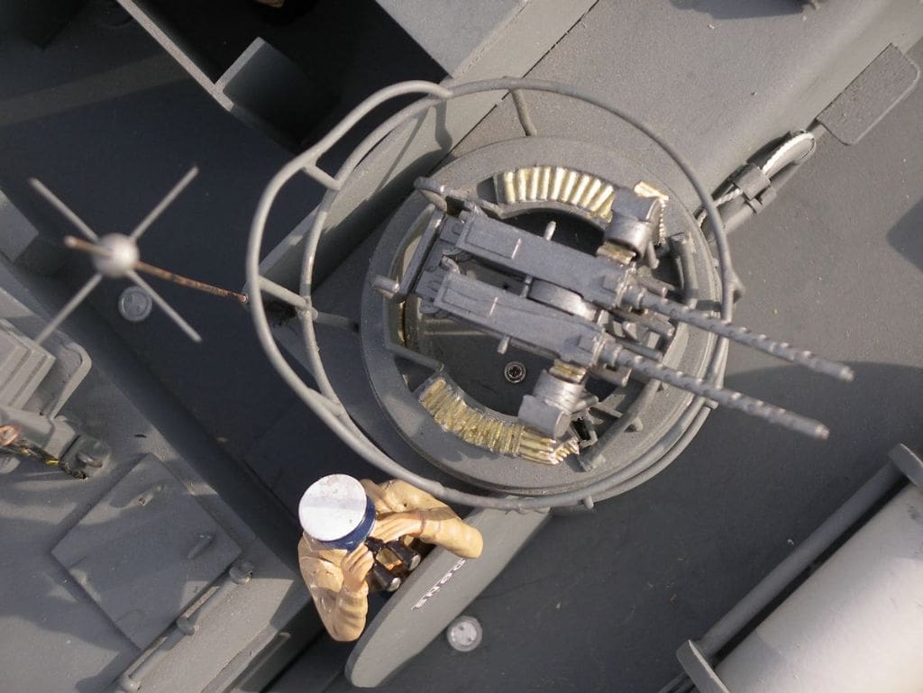
This design was not very successful as the rotating part of the turret tended to work loose after a few operations. The design was modified slightly by first screwing the servo disc to the servo drive shaft using the normal centre screw and then attaching the rotating part of the turret to the disc with two small screws, a bit fiddly to centralise and locate everything, but it was possible. Both machine guns turrets rotate from one of the transmitter channels but occasionally still tend to stick. Overall if I were to start again I would do this differently. The micro servos are really too fast, too high geared and have too small an operating arc. It would be better to mount a bigger and slower servo with more torque inside the main cabin, rather than try to make the turrets and drives self-contained items. However, the final result looks quite good, Photo 19, but is still lacking suitably attired gunners to sit in the turrets.
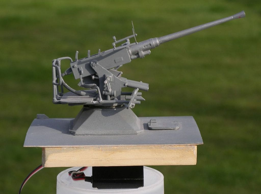
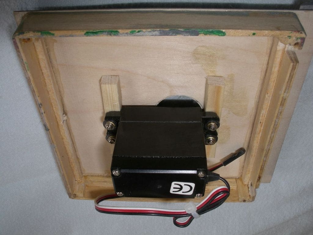
The 40 mm Bofors gun was again constructed from a John Haynes kit of parts and was mounted on a ply panel which covers the rear section of the deck, Photo 20. This panel provides access to the radio gear, rudder linkage, switches and connectors. It is not secured other than being a close fit in the hull and can be lifted by pulling up on the rear hatch which is raised off the deck just enough to get a couple of fingernails underneath it to grip. Again this gun is driven by a servo but in this case there was much more room and a sail winch servo was mounted below the gun, Photo 21. A servo drive disc was attached to the lower part of the gun mounting and this just pushes on to the servo splines, Photo 22. This arrangement works much better than the machine gun turrets with plenty of torque and smooth operation over approximately 270 degrees of travel.
Choice of colour and painting
Originally the model was to be sailed by my wife Elizabeth and she liked the original grey colour scheme better than the more common olive green found on most US Navy PT boats. At the end of the war, PT boat production was still in full swing in the USA and many of the final batches of boats were sold or lend leased to other nations. In 1951 ten Elco PT boats were supplied to the Norwegian Navy. It was therefore a joint decision that the model would be finished in Humbrol Sea Grey and carry a Norwegian flag. The first boat supplied was PT602 which was named Snøgg, which is Norwegian for ‘fast’. Elizabeth thought this would be a particularly good name, since given the combination of armament the boat carried, it was bound to be the kiss of death for anything it met in combat! I have tried to find details of the actual boat as supplied to the Norwegian Navy but so far without any luck.
On the pond
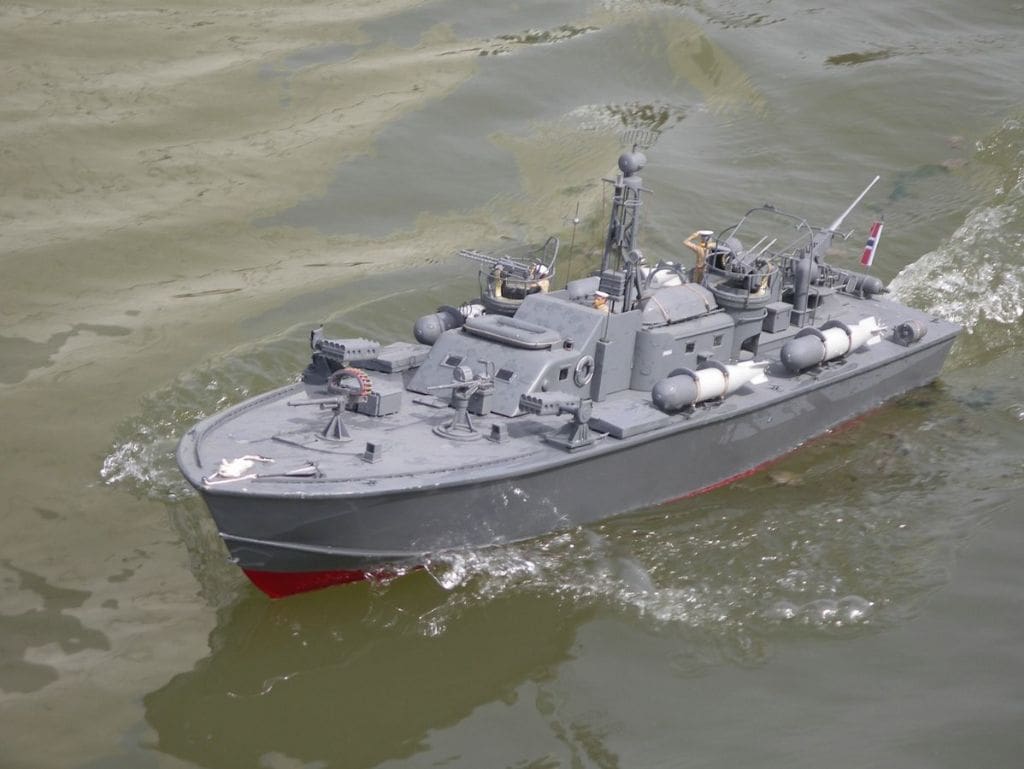
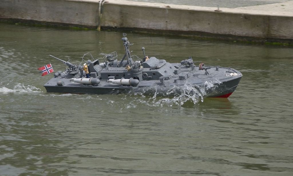
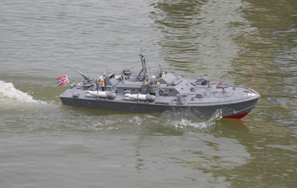
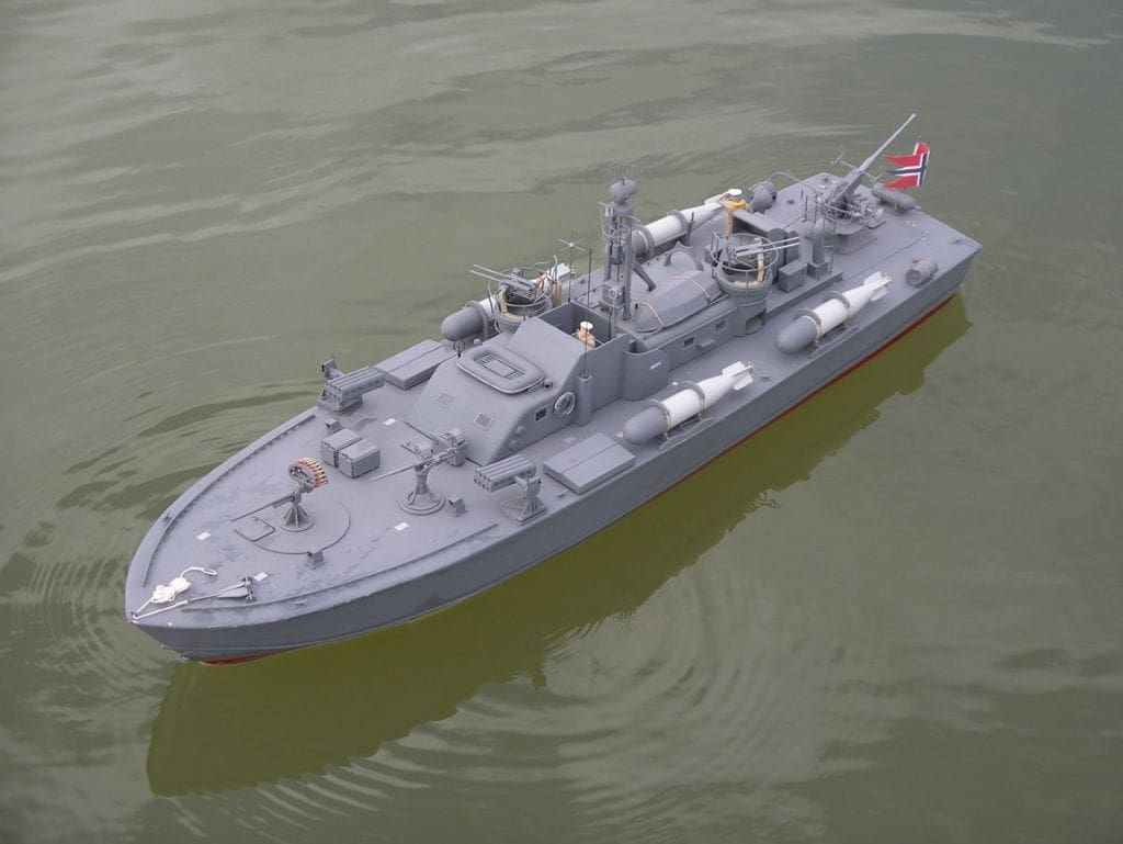
The finished boat looks good on the water, is very manoeuvrable and at high throttle settings achieves a scale planing speed, Photo 23. There is plenty of detail to add interest and when the boat has been displayed at club exhibitions and regattas it attracts the attention of the small boys who want to know what all the guns are for and whether any of them work.
My wife has now graduated from sailing Snøgg to building model yachts which has the benefit that I get to sail it, but it’s had the unfortunate side effect that we began to compete for bench space in the shed. However a major garage conversion and workshop building programme has resolved the territorial dispute!
I learned a lot about electric motor drives in the process of the boat’s development and fortunately most of the discarded items are now finding their way into other models. If I were to start all over again I would mechanise the machine gun turrets differently, but apart from that I am pleased with the end result, which is a pleasure to look at and sail and goes to show that you don’t need the latest most super detailed kit to gain pleasure from our hobby.