Getting underway
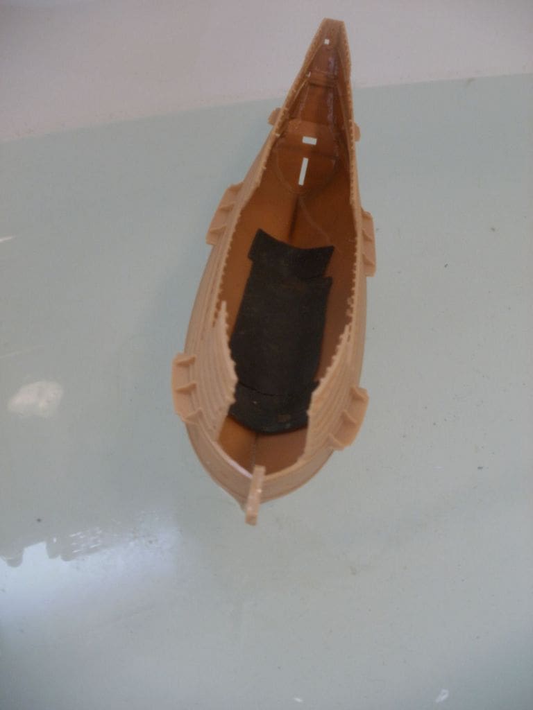
With only a vague idea of how to proceed, construction started anyway. My ideas are always vague when I commence a project, but usually, although not always, they become firmer as the project progresses and this was to be no exception. Looking at the kit parts I was glad to see that they were quite nicely moulded with very little flash and seemed to fit together quite well. Luckily they were also quite large, which as I am now getting older, becomes more important for a whole range of reasons! Work started by joining the hull sections together and immediately I could foresee problems due to the height of the stern of the model, the notable tumblehome shape and extremely narrow beam. Anyway, a few preliminary floatation tests showed that it was in fact relatively stable with quite a lot of lead ballast placed low in the hull, so I plodded on with the project.
Rudder
This was next on my list of things to do as the complete fitting in the kit was permanently fixed to the hull, which was no good to me at all. It was also very small, even though to scale, and one thing I have realised over the years is that rudder size does matter with sailing models and an enlarged version is definitely an asset on a scale sail model, something that Dave Petts’ has also alluded to.
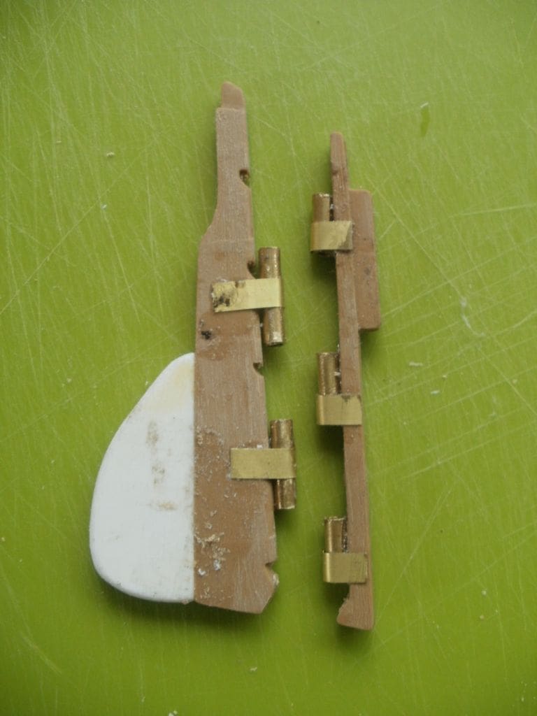
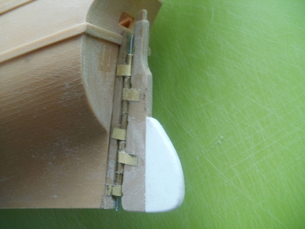
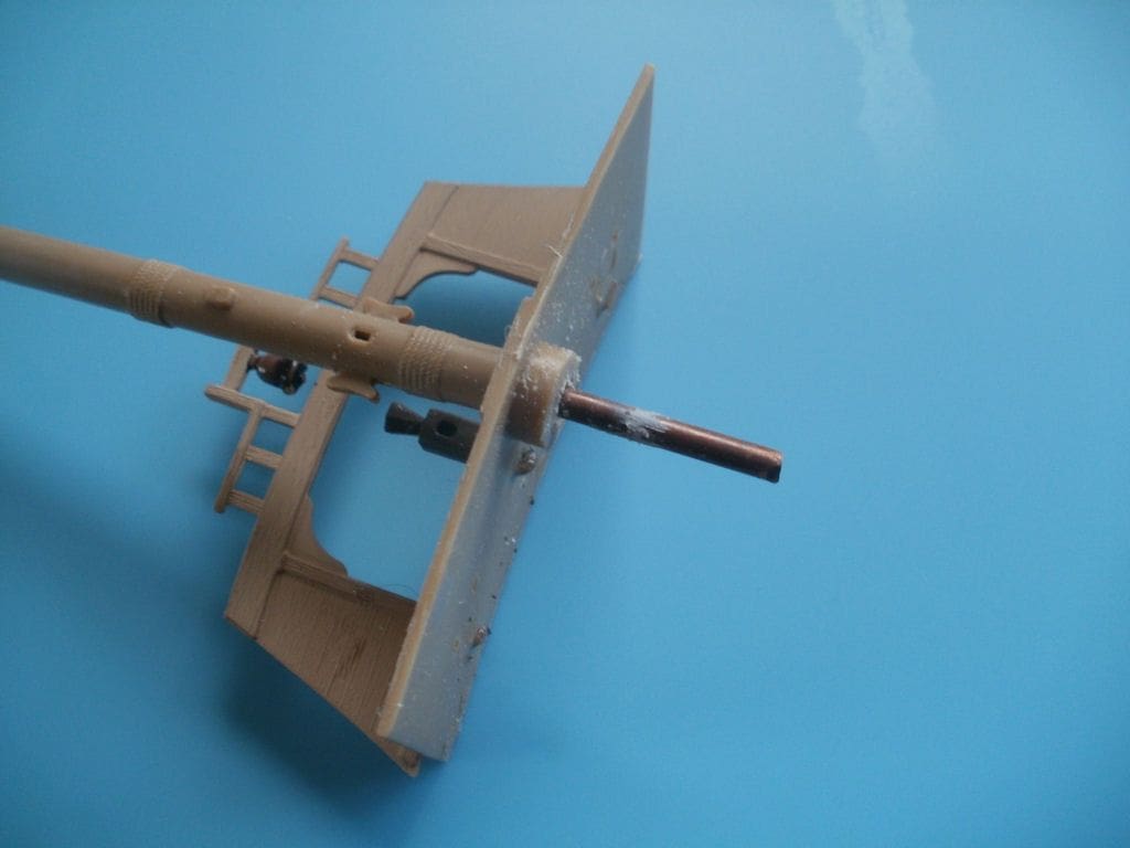
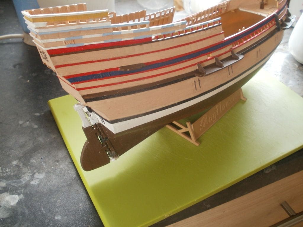
To commence, the rudder was cut away from its stern post, which would normally be glued into the rear of the hull, and glued (normal polystyrene adhesive) to an extension piece to increase its surface area. To make it operational, lengths of brass tube were glued along the rudder and its now separate stern post piece, so that they interlocked. These tube hinges were held in place with thin brass strips bent around the tube and then on to the sides of the rudder blade. Redundant strip from brass etched carrier sheets are very thin and flexible and these should never be discarded when using photo-etched components as they are handy for all sorts of things. A brass rod through these tubes allows the rudder to pivot freely, but it is necessary to also fit an extension piece to the keel underneath it all to prevent the pivot pin from slipping downwards and out, to be lost no doubt at the most inconvenient moment when ay least 50 metres from shore!
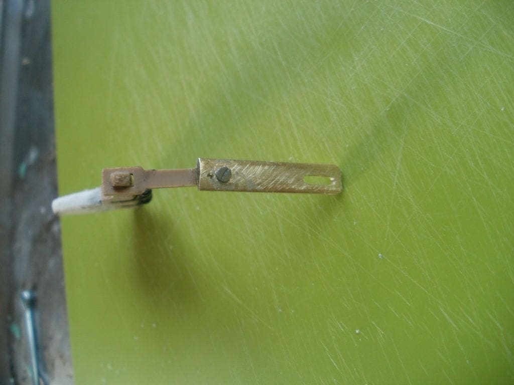
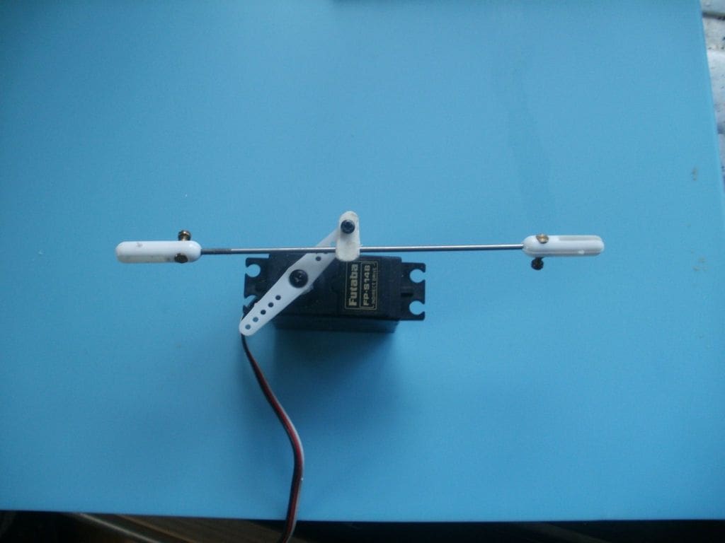
The rudder on Mayflower was operated by a tiller rather than a steering wheel, and is attached to the top of the rudder post and pokes through a hole in the transom, but how to operate it in miniature? Due to the extreme narrow beam of the model there was no room for a normal linkage, perhaps with the servo alongside the tiller arm, so a system previously used on the IJN Kirishima battlecruiser model was adopted, based around a pin and slot system. Using a short length of brass strip, a slot was formed about 1cm long by 3mm wide and which allows the free movement of a 10BA screw.
Enjoy more Model Boats Magazine reading in the monthly magazine.
Click here to subscribe & save.
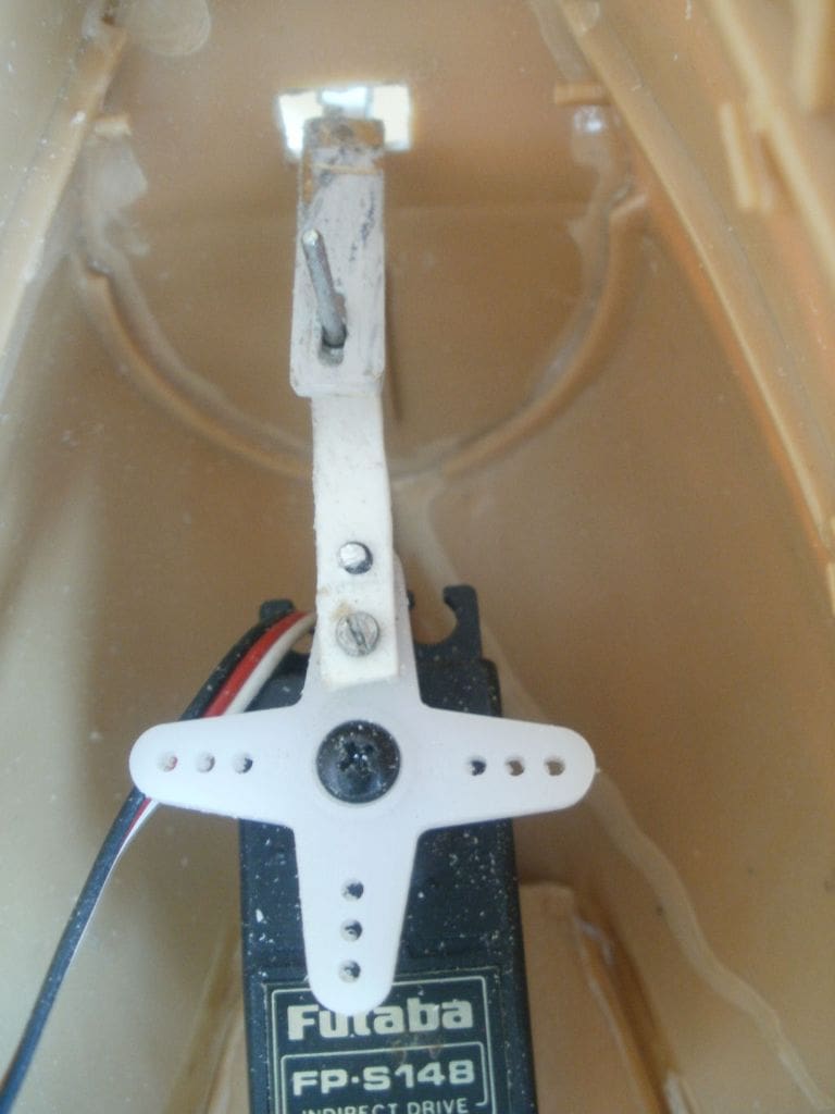
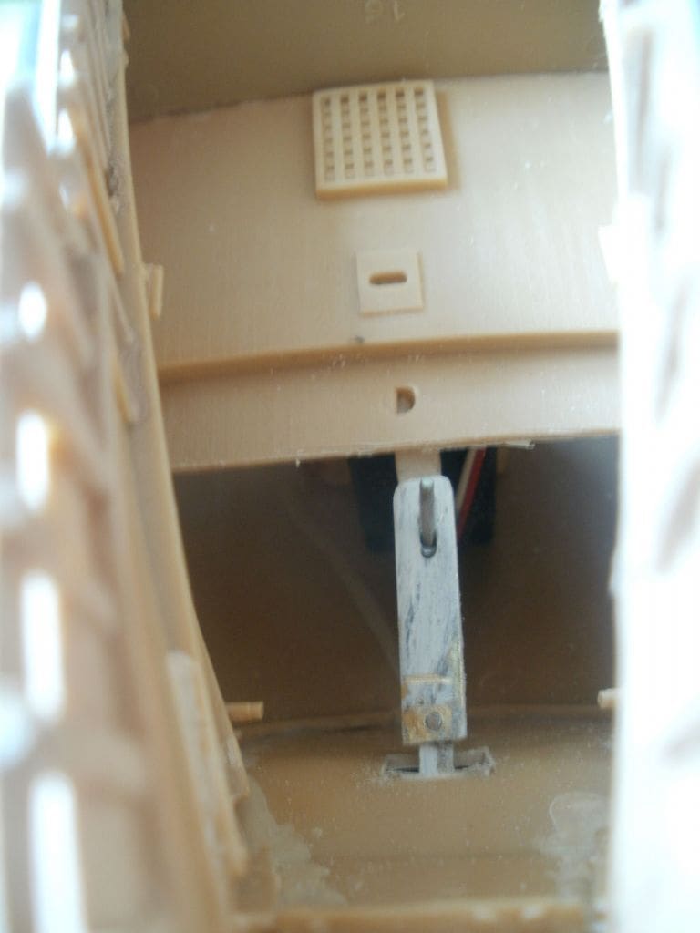
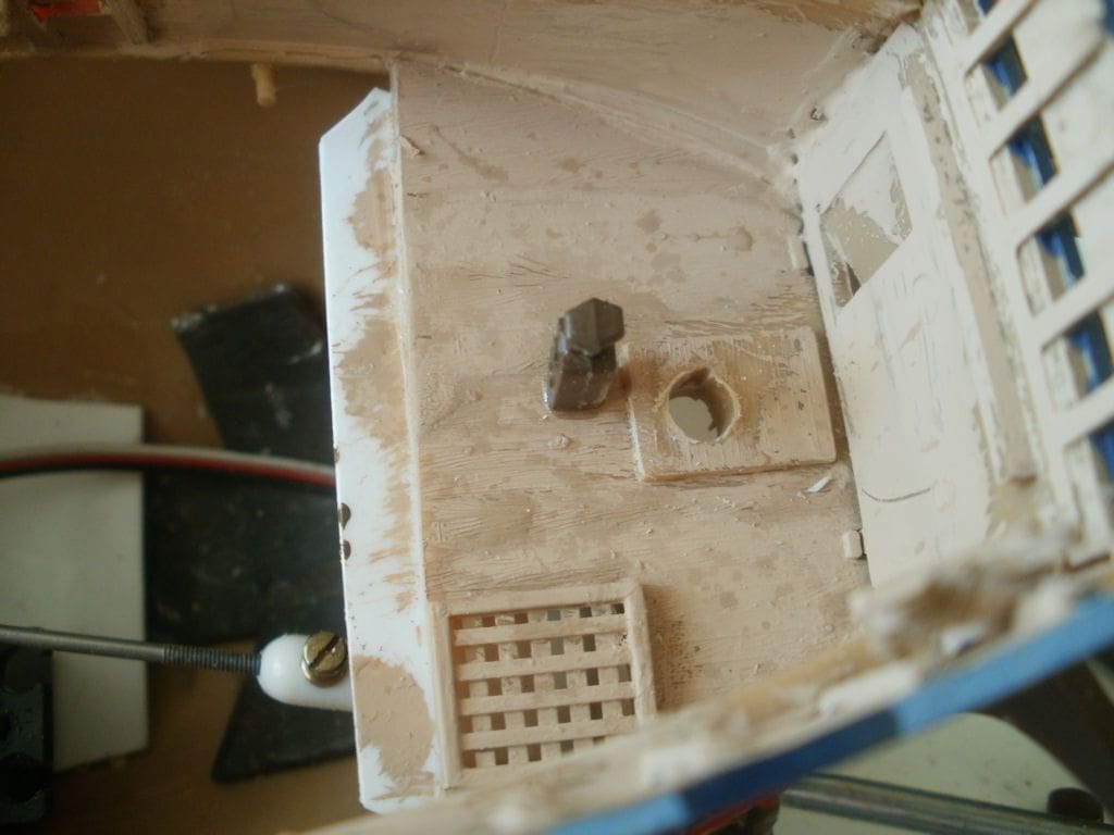
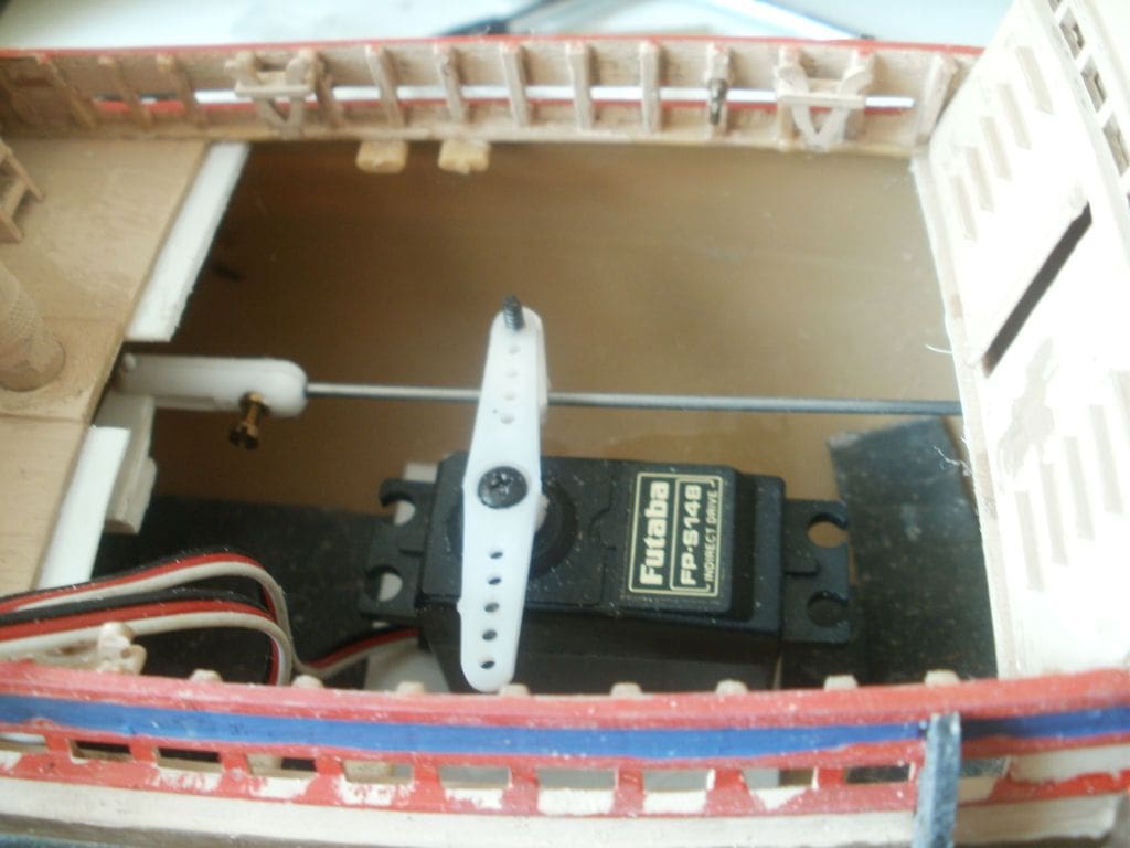
This length of brass strip was then attached to the tiller arm using small screws and a little superglue; the whole rudder assembly was then mounted permanently to the stern of the hull with the tiller arm inside the hull. An extension arm was also attached to the servo output with a 10BA screw (actuating pin) at the outer end, which fitted into the slot in the tiller arm. This servo was superglued to a support (well it was a spare servo!) with the actuating pin at the mid-point of the slot. When operating the servo it has to be remembered that if the arm moves to the left, the rudder moves to the right, so it might have to be reversed electronically by the transmitter, but I must say that the system works very well. This whole project was done very much on a ‘what’s in the scrap box’ basis and that will also be evident later when you consider this model’s colour scheme, but now yet another problem reared its ugly head.
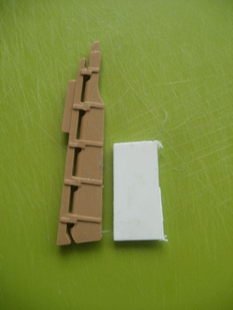
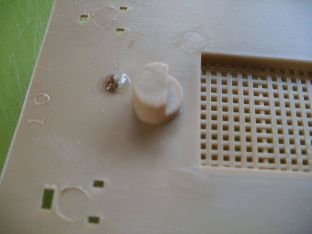
When the deck was test fitted over the proposed rudder linkages, it was obvious that internal clearance was at a premium and worse, the boss supporting the mast on the underside of the deck piece fouled the rudder mechanism. Surprisingly the solution turned out very well, as the part of the deck in question was actually hidden when the model was finished, so was simply cut away including the mast base boss. This gave ample room for the rudder operating mechanism and as a bonus, this deck offcut was an exact size to act as the support for the servo!
Operating the sails and masts?
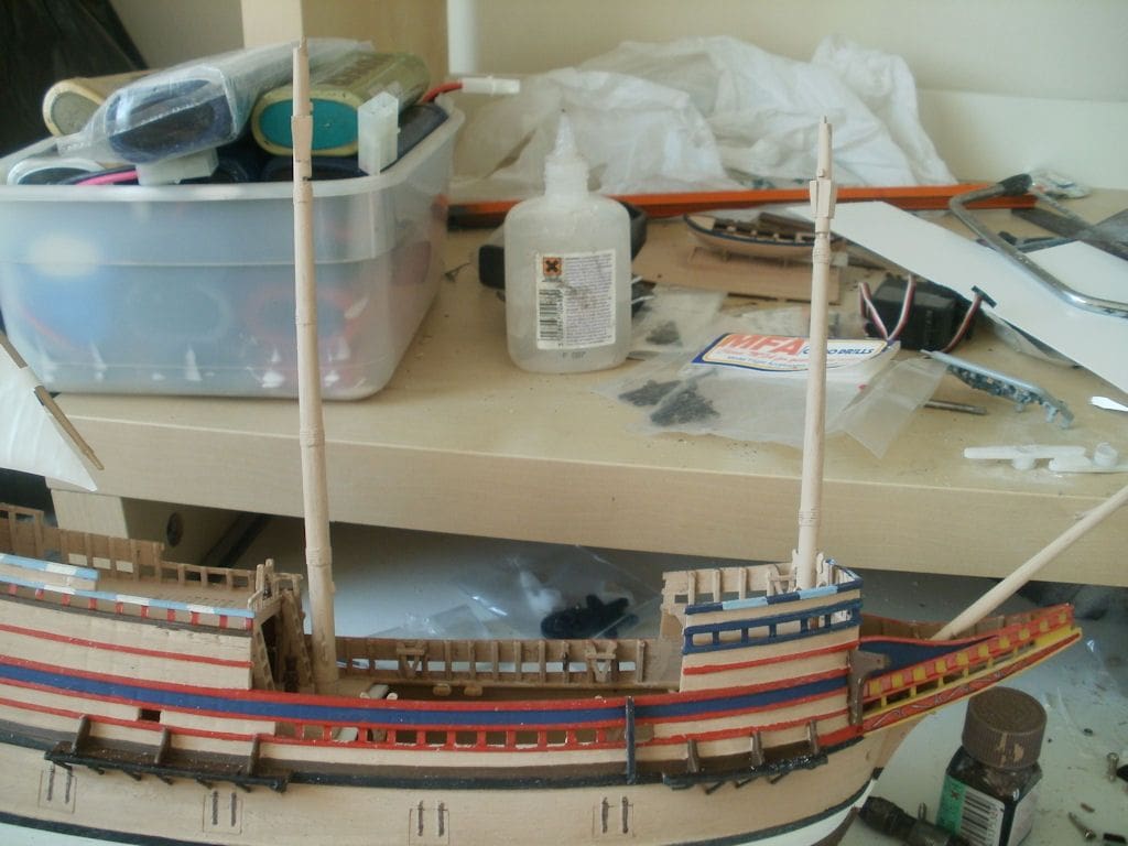
How to get the masts and sails to work was still a vexing question, so whilst thinking about this, I progressed with the overall construction and painting of the model. Generally speaking, this was straightforward, although because of the vessel’s shape, the ends of deck had to be reconfigured a little.
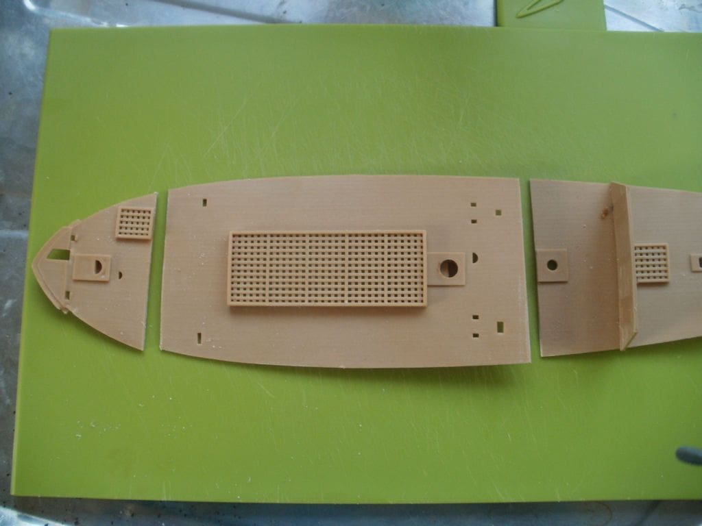
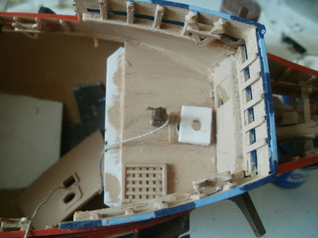
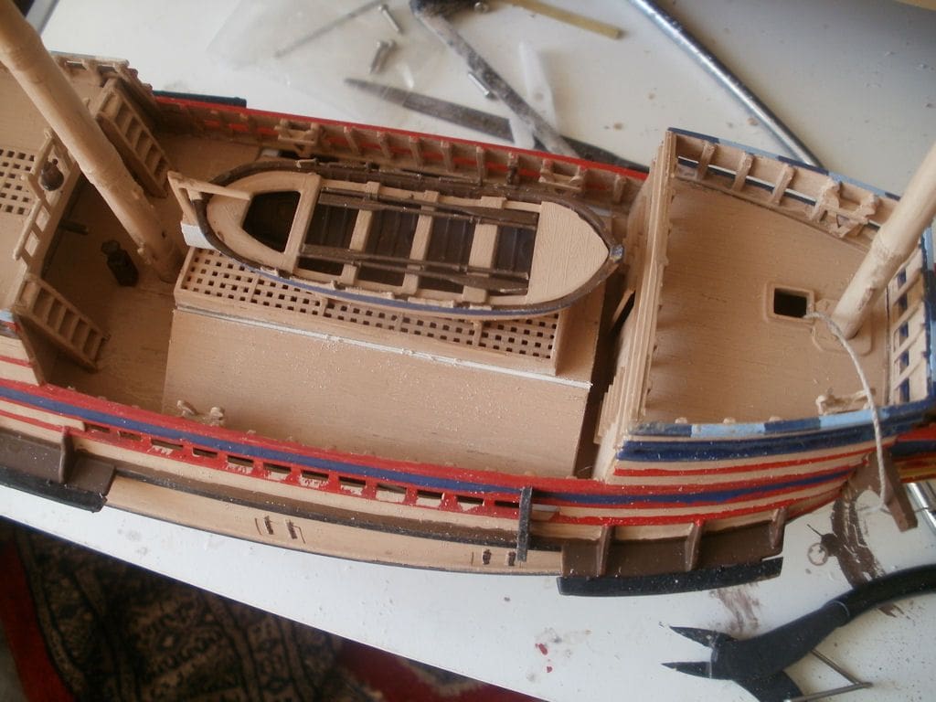
The main deck was cut into three pieces for ease of internal access, with the forward and stern portions being permanently fixed into the hull. The foremast is on the front section, with the mainmast on the centre removable section. As construction progressed, there was a minor Eureka moment when I realised that it would be possible to install a second servo amidships rotating the two masts via cranks and a coupling rod – anticipation and excitement was starting to mount!
The problem of securing the rigging could possibly be overcome by using a sort of slip ring, however in order to do this it would be better for both masts to be on fixed sections of the deck. Consequently, the centre removable section was cut again immediately behind the grating, which allowed both sections that supported the masts to be permanently fixed.
At this stage the majority of lead ballast was also permanently fixed in place within the hull as once most of the decks were fitted, access would be very difficult. Minor trimming of the model could be easily resolved at a later date, but shoe-horning in lumps of lead with decks all in place would have been awkward to say the least.
Masts
The foremast was a bit of a problem in that it is supported by two decks and worse, the supporting holes seemed to be incorrectly positioned and this revealed itself by this mast being at a totally different rake angle than the other two. Solution? Open up the hole in the lower deck and fit a cover strip of styrene with a new hole in the correct position, which resolved one problem, but created another and having said all of that, it may have been correct in the first place! After completion, I was watching the film ‘Mayflower’ on TV that chronicled the voyage to The New World and one picture showed a replica Mayflower in profile. To my surprise, it showed all three masts splayed at different angles and not parallel raked. Okay, not quite to the extent on the model, but splayed nevertheless. So in view of the later problems caused with modifying the mast mounting, leaving it alone might have been a better option. The mainmast is only supported by the upper deck which makes it relatively unstable if unsupported.
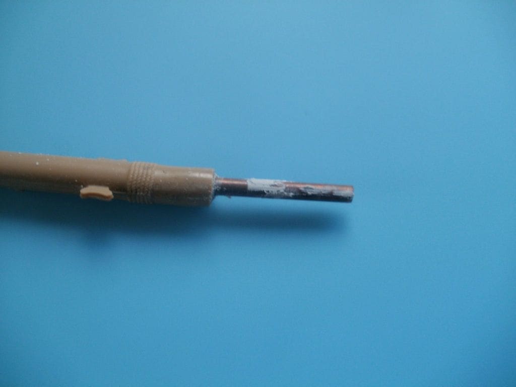
The rotating masts both needed to be extended downwards. This was a simple enough job of drilling their bases with 1/8 inch (3.2mm) holes and fitting suitable brass rod extension pieces into them. In practice, I would recommend making the mast bottom extension rod pieces long enough to reach the bottom of the hull, where a support bracket glued to the inside of the hull with a suitable guide hole for the 1/8 inch rod makes for a much better mechanical arrangement, particularly for the mainmast. Both moveable masts should be able to rotate freely, but no attempt was made to alter the mizzen mast which was glued permanently in place and the next step was to link the fore and mainmast.
Linking the masts
A servo was temporarily placed amidships and a length of rod cut to the approximate distance between the masts. Commercial clevis connectors that could be screwed and glued to each end would complete the linkage. Operating arms for the masts were cut from styrene sheet which could be firmly pushed on to the mast bottom extension rod pieces whilst these are in-situ as it is impossible to install them before fitting the masts into the hull as they are beneath the deck.
A central pivot was made to connect this connecting rod to the servo arm and with a little bit of trial and error, the correct lengths were determined. A word of caution here, as you must make sure the two masts and their sails/yardarms are parallel before finally gluing everything that needs to be glued. The yardarms (and sails) are already angled to starboard when the masts are at their mid-points, consequently it was necessary to arrange that the servo moved only to the left, rather than about its usual neutral to get the system to work properly.
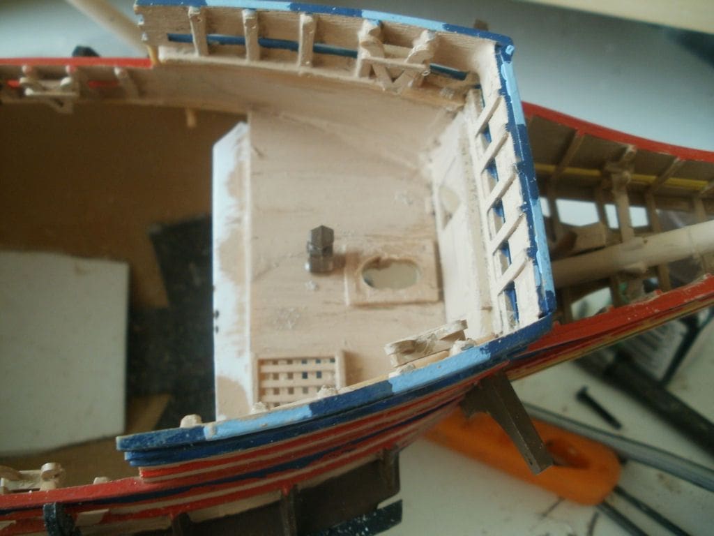
The time had now come to fit the top deck which proved a problem owing to the extreme tumblehome of the vessel’s sides. Before the other decks had been glued in place it was possible to spring these sides to get the top deck to fit, but this was no longer possible. Further head scratching and ‘brain ache’ occurred before a solution presented itself. Two longitudinal, partial thickness, cuts were made along the deck either side of the deck grating. It was then possible to partly bend the deck into a U-shape that was still flexible enough to return to being flat. So to fit the deck, it was compressed into this U-shape until it could clear the hull sides and then be flattened on to the deck supports. This turned out very well and is a method that I will use again, if and when the same situation arises.
Painting, rigging and sails
Painting
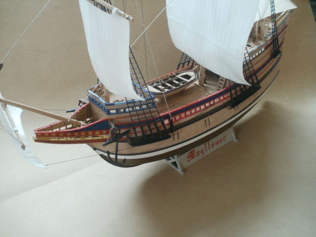
This was very difficult to follow (for me anyway), so I tended to use the box art picture and the end result was quite pretty and as you can tell from the earlier pictures, some of the painting was done as construction progressed. There were so many different shades of brown for instance, that in the end the only one used was the one in stock. I usually advocate the use of masking tape when demarcating such a colour scheme, but in this case it was all done by eye. A further ‘bath’ test was done now before rigging as it would be easier to add the ballast weights without sails etc. being in place.
Rigging
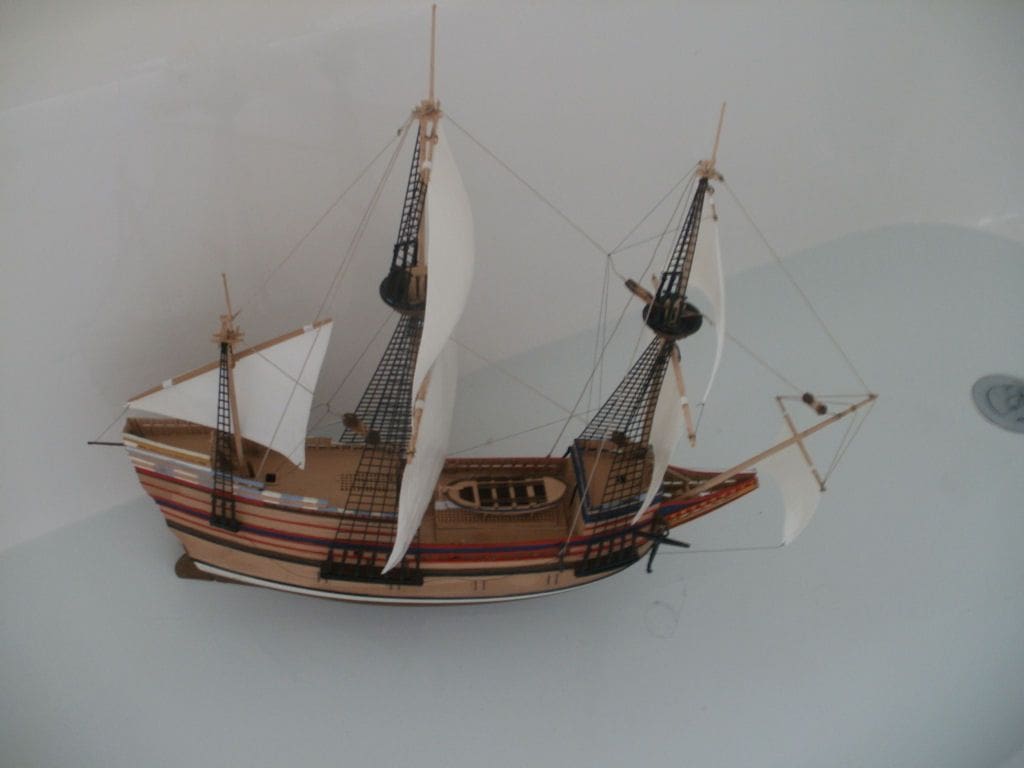
This needed to be flexible and yet still supportive. The ratlines came manufactured and readymade, thus a great saving in time and effort and starting with the mainmast, they were flexible enough to twist with it so I moved straight to the foremast.
This is where an unexpected problem caused by my previous efforts raised an ugly head again. By fitting a support plate to change its angle, the foremast had been unwittingly raised a little. I had realised this at the time, but had not reckoned on the consequences which were that the ratlines were now too short and would not fit properly. In the end, they were simply glued to the sides of the foremast which still looked acceptable in the circumstances. The rest of the rigging was finished more or less as indicated by the instructions.
Sails
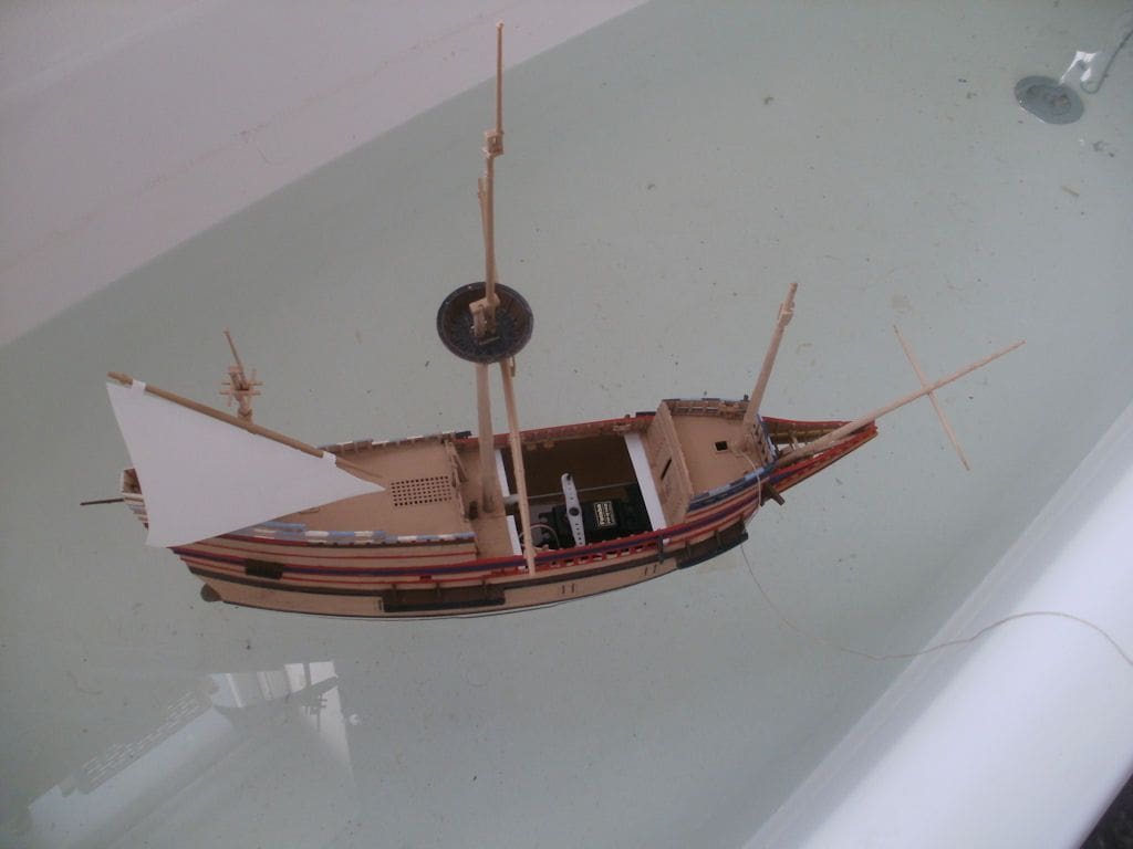
The supplied sails are made from very thin vacuum formed polystyrene. It was necessary to ensure that there was enough space so that the removable portion of deck could in fact be removed, without fouling the rigging and to make the cords from the yardarms very much on the slack side, to allow for rotation of the masts. Basically the model was now finished and more ‘bath’ trials were on the cards, so off to the bathroom again! First, the general trim and stability was checked again when fully laden with the receiver and batteries etc. and surprisingly, significant extra ballast was still required. Although the model sat in the water very well, it was too unstable when heeled to port or starboard, so additional ballast bought it deeper in the water, at the same time improving the stability.
As the real Mayflower did not possess an engine I needed wind for the model to move which was supplied by my daughter’s hairdryer and it was then I began to think about it all. When working out speed it can be directly connected to scale, but what about wind? What does a Force 10 gale equate to in this scale? I really had no idea, so I simply switched on the hairdryer (cold mode!) and applied it to the sails in various ‘angles of attack’ to check speed and stability.
It was really then that the need for the extra ballast became self-evident. By the way, at this crucial moment whilst leaning over the filled bath, don’t drop a live mains powered hairdryer into the bath water! It is best, unless you want a direct connection to the National Grid, not to do as I did, but generate the wind by huffing and puffing instead.
At the pond
I felt that I should really dress the part of a 17th century pilgrim, but that may have been a little extreme, so in the end I did not bother. The day had to be chosen carefully as there was no point in going if there was no wind or, at the other end of the scale, a raging hurricane. It was evident from the bath trials that the model responded very well to low levels of ‘puff’.
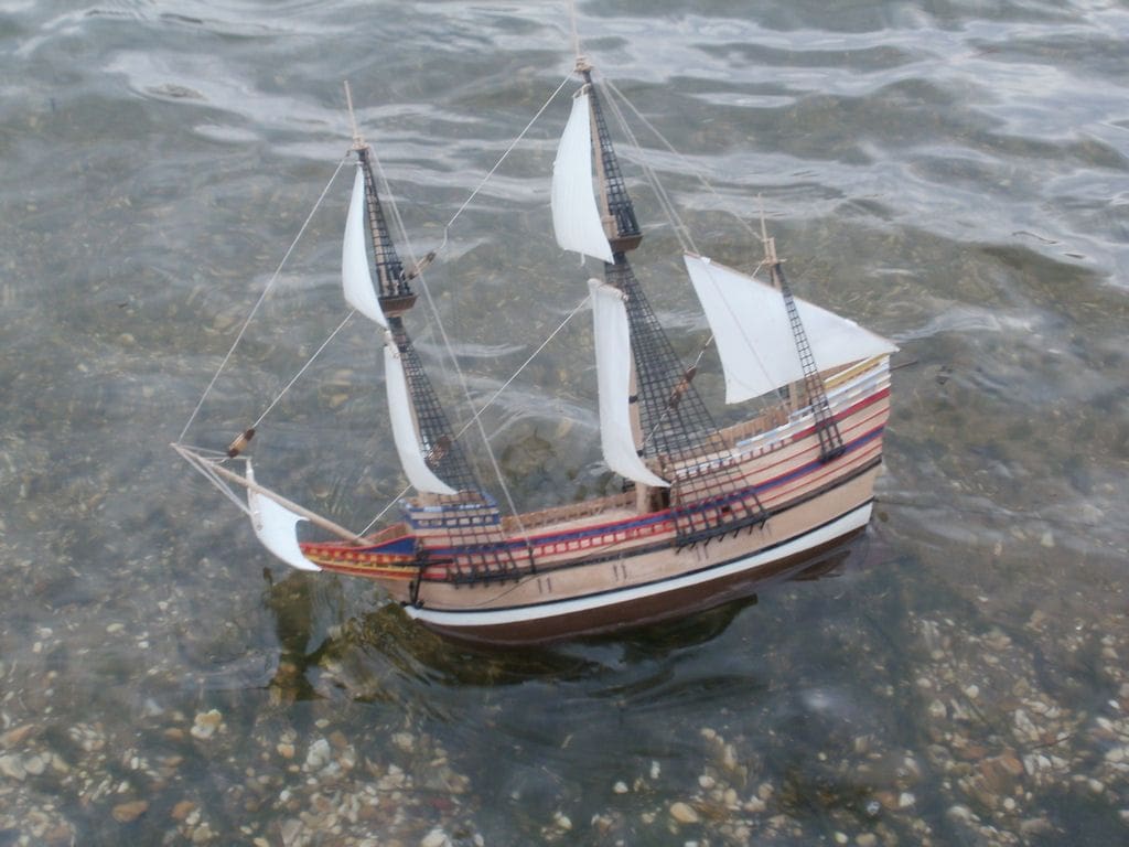
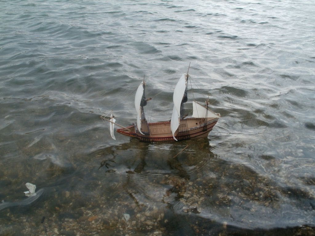
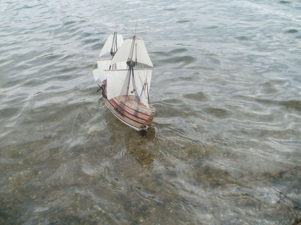
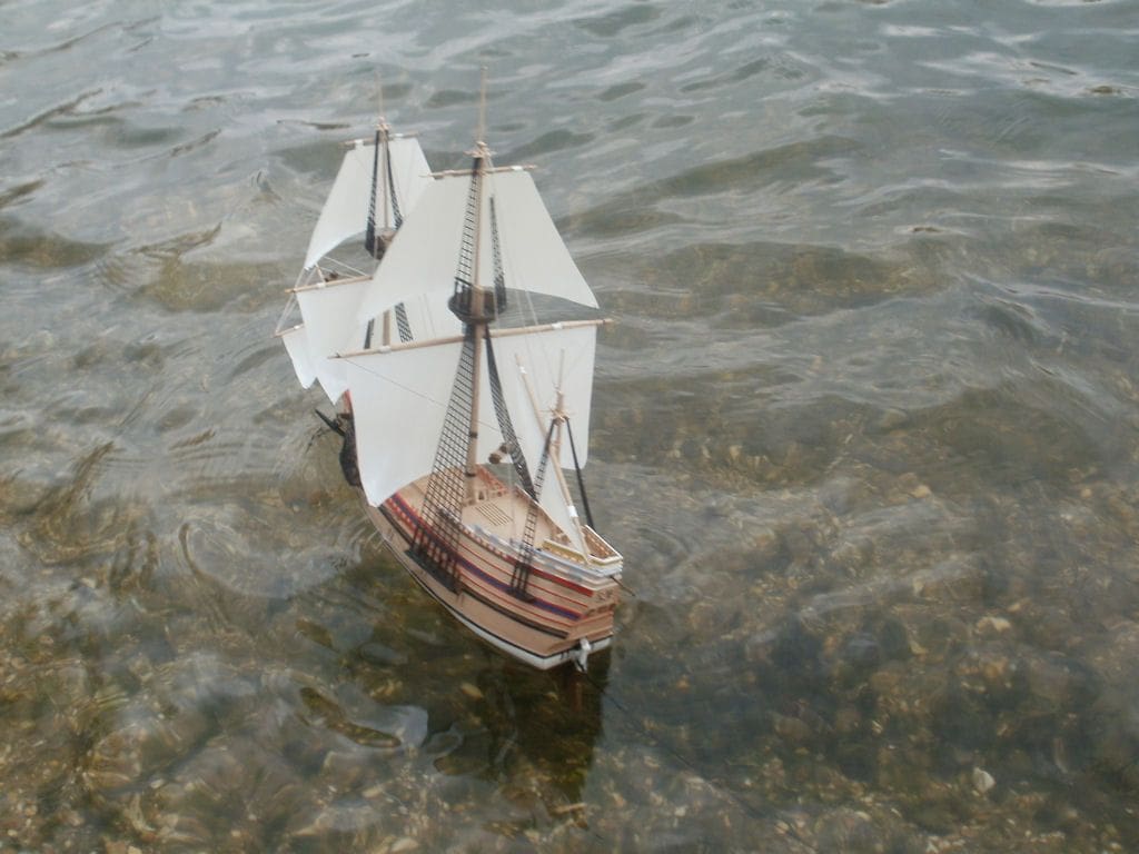
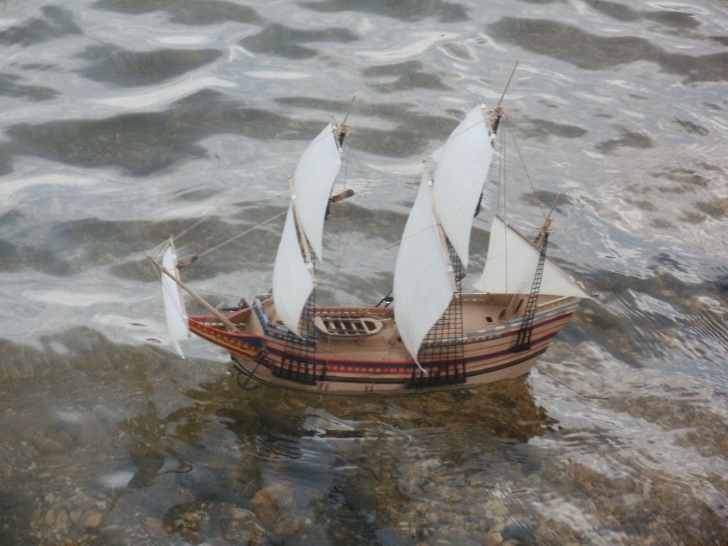
As it so happened, on the chosen day, it must have been a scale hurricane blowing as I was being pulled along by the wind when walking from the car. The wind was blowing from right to left and slightly on-shore, so not exactly ideal for first trials, especially for a novice like myself. The rudder was tethered so that Mayflower could be hopefully retrieved as this maiden voyage looked more and more suicidal. The mizzen mast sail looked odd, but that is how it is depicted in the kit and on the box cover, although other pictures show it slung the other way.
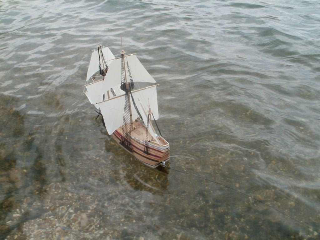
Well, at times Mayflower took off like a rocket and would heel over alarmingly, but she never capsized which is a testament to her construction. After a while I got the hang of it a little and was able to send the model further out on the lake, but am still not sure I have been able to master ‘tacking’, ‘going about’, ‘running before the wind’ and the such-like.
One problem not anticipated, was that in such rough weather the water came on to the main deck and was able to enter the hull’s interior through the removable deck section. In hindsight it would have been worthwhile trying to waterproof its edges, although as mentioned earlier the weather was extreme at the time, at least for this 1:150 scale model.
Conclusion
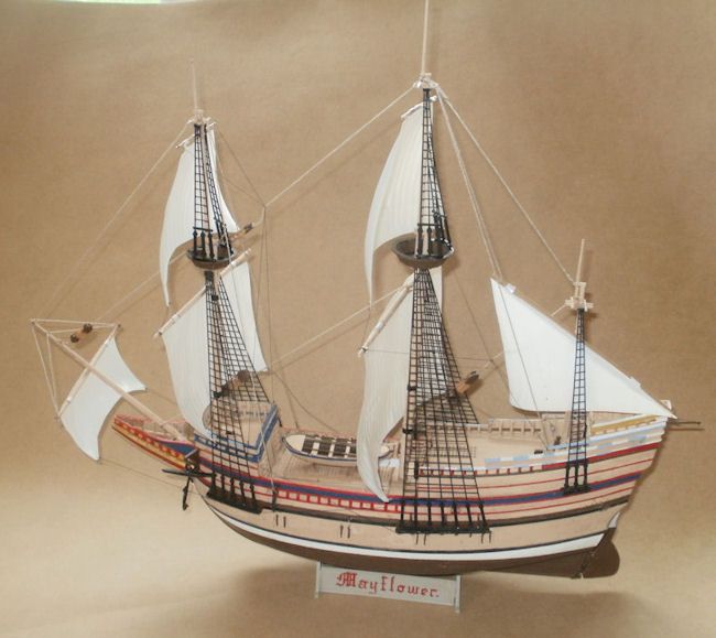
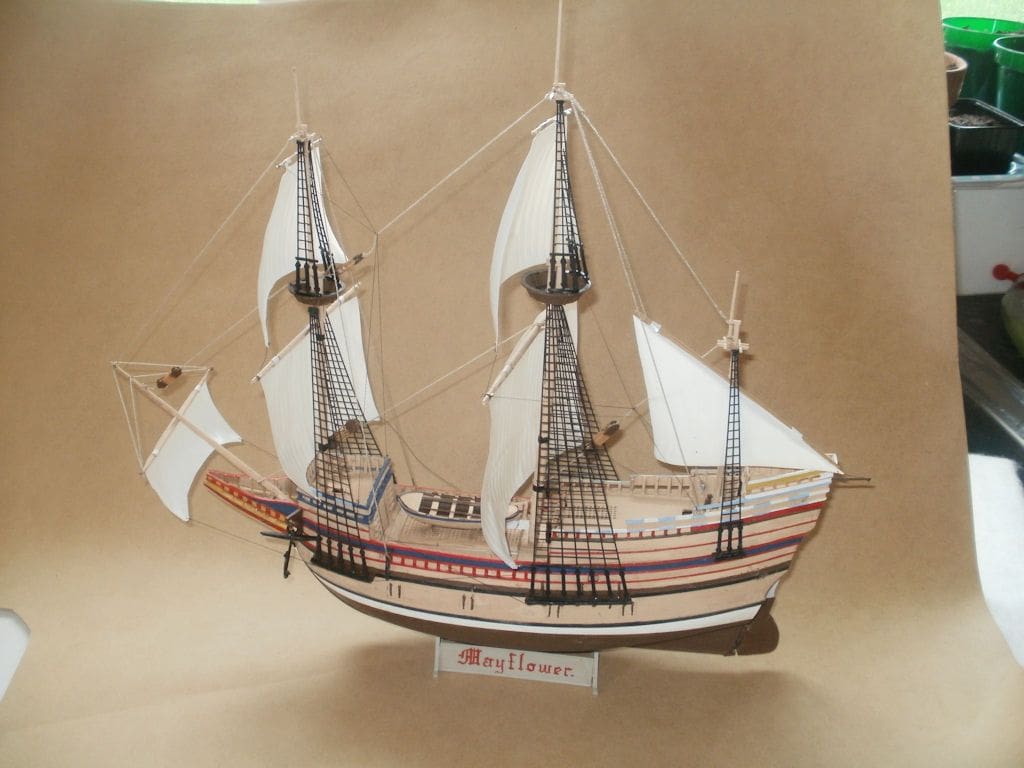
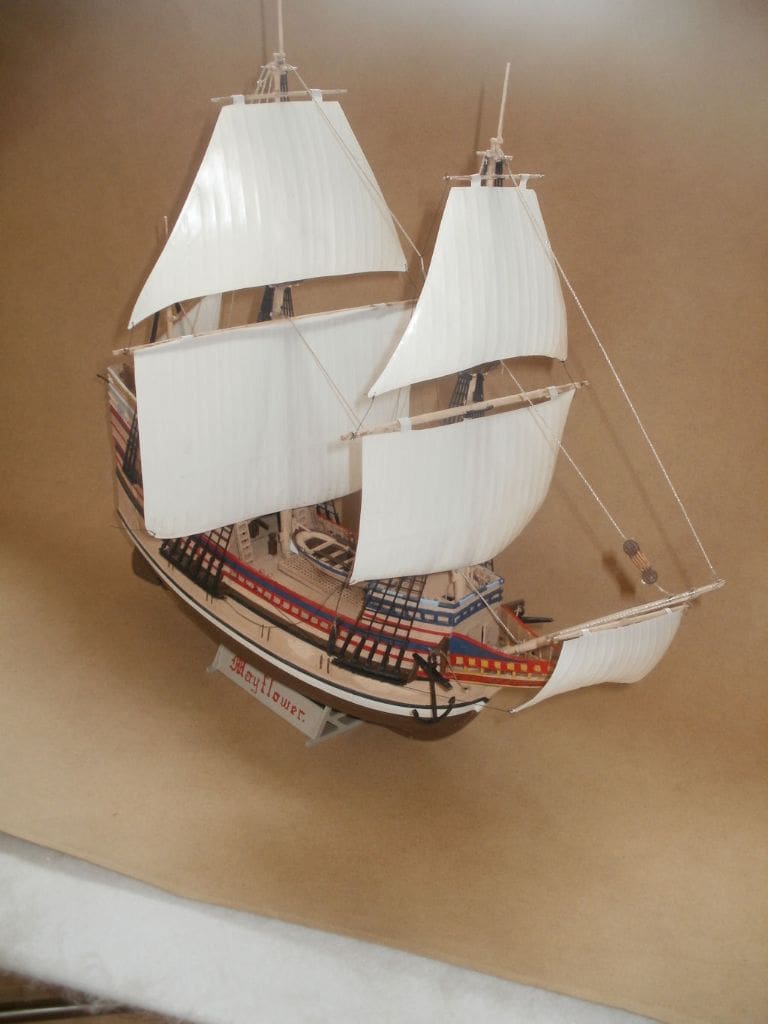
Mayflower is a pretty little boat and looks the part on the water with her billowing sails. Having attempted this model sailing ship with rotating masts, I may attempt something a bit more grandiose in due course. It has in the end been a simple enough conversion, a bit of fun and is different and relatively inexpensive, the secondhand kit from a car boot sale costing next to nothing and everything else coming from the spares/unused box.
Dr Marcus Rooks
(This is an example of one of our articles, first published in our January 2014 issue. For captions to the photos, just hover your mouse over the top of each one.)


