My first r/c paddleboat was loosely based on an early steam tugboat. This gave the right proportions for a compact yet practical model which proved to be both educational to build and great fun to sail. The educational aspect was the discovery that the paddlewheels, something I initially feared to construct, could be made simply and effectively from plastic sheet. They proved strong enough for the rigors of general use yet looked realistic enough when the model was sailing. The fun side was having two independent geared motors for both steering and propulsion. By using the transmitters built in ‘elevon’ (a model aircraft function that works just as well in boats!) mixing to operate two speed controllers, the model could be sailed using conventional rudder and throttle commands. But, by leaving the throttle alone, using the rudder stick would cause the model to rotate on the spot. This design, called Tipstaff, was published in the April 2005 issue of Model Boats.
Other ideas
While sorting out what to base my first paddleboat on, I thought about the Confederate Blockade Runners. These were designed to be fast vessels capable of evading the Union Navy forces which tried to close off the Confederate sea ports through which cotton flowed out and valuable war materials flowed in.
These vessels were designed for speed and as such had high length/beam ratios. The narrow hulls would have made installing two independent motors rather more tricky than was wise for a first attempt at an r/c paddleboat. I was also worried that their narrow beam might have caused problems if the model rolled excessively. The paddles would have variable immersion and probably produced weird handling. The limited amount of information on these Blockade Runners was the final blow to this idea and I sensibly (for once) turned to the safer and, as it turned out, successful idea of a tug based model.
Enjoy more Model Boats Magazine reading in the monthly magazine.
Click here to subscribe & save.
Fate takes a hand
Several years ago I volunteered to act as a supervisor for courses run in Universities throughout the UK. They are designed to introduce youngsters to engineering careers and opportunities. This has become one of those annual commitments that only a death certificate will excuse you from. It is a demanding week but, luckily, great fun and you do learn about what is happening at the frontiers of your profession. In 2005 I was sent to supervise a course at University College London, the week of the tube bombings, but that was thankfully another story. Across from the University buildings was a well stocked bookshop, and the first moment of free time saw me browsing through their shelves.
I found a rack of the well known Osprey Publishing’s booklets covering many military and historical themes. The one that caught my eye was the one of their New Vanguard series ‘Confederate Blockade Runner 1861-65’ (ISBN 1 84176 636 4). This is a rather slim volume but excellently written by Angus Konstam and superbly illustrated by Tony Bryan. A copy was promptly purchased and read during any free time in the rest of the course. The result being quite predictable, I journeyed home from the course with the draft plans for a new model.
Planning time
The Osprey book included enough information for me to set about designing a respectable model based on these Blockade Runners. Still being somewhat experimental, this model was going to semi-scale, functionality being placed ahead of accuracy but without, hopefully, losing realistic appearance whilst sailing.
The lengths of these vessels varied between 200 and 300 feet (60 -90 metres). As I planned to make the model around 30 inches (75 cm) long, a scale of about 1:100, or 1:96 (1in=8ft for diehard Imperial modellers!) looked promising. As they were built for speed, Blockade Runners had relatively narrow beams, and at this scale I would be looking at a model beam of 3.5 to 4 inches (9-10 cms). A few calculations revealed that a model of these proportions would have a displacement of around 5 pounds (2.3 kg).
Fifteen knots seemed like a realistic top speed for the full sized vessels. The corresponding dynamic scale speed, which is the speed at which the model would produce the same wave pattern, would be this speed times the square root of the scale used. In this case it produced a model speed of 2.5 ft/sec (0.75 m/sec) which looked like a reasonable value for this size of model.
A paddlewheel of 3.5 inches (9 cms) diameter seemed to be the right size for this model, so some idea of the rotational speed was needed. If you assume that the paddle acts like a wheel then one revolution ought to advance it some 11 inches (28 cms), i.e., the circumference of the wheel. Clearly this is unrealistic and some ‘slip’ is bound to occur and I figured that 25% slip was a sensible guess. This gave an advance of approximately 8 inches (20 cm) per revolution. Thus, the desired model speed ought to correspond to 3.75 revolutions per second or 225 rpm.
Motive power
Up to this point I had not come to any definite decision on how this model might be powered. The success of twin independently controlled motors on the previous model made this a tempting idea. The amount of space inside the hull would have resulted in a ‘tight’ but not impossible twin motor and r/c installation. After a little thought, it was realised that this model would not require a lot of power and a single motor of the RE 385 type ought to be more than adequate. This lead me down the route of one motor driving coupled paddlewheels and steering with a conventional rudder. At this point the experts will pounce and say that such a model is bound to have poor steering. I hoped that an enlarged rudder, plus a couple of other tricks, might minimise this problem. Anyway, I’m an Engineer, so was well into not reading the instructions for new equipment! We never listen to expert advice until we have tried out an idea.
Achieving the reduction in motor speed to match the desired paddle speed was the next problem. Rough calculations showed that a reduction of around 30:1 was needed. This could be produced by using two pulleys and/or gears in series, say a 5:1 and 6:1. It would require some fairly accurate work to avoid excessive friction or slippage, something that modellers without the right tools and skills might find to be a problem. An obvious answer was to use a commercial geared motor, a good idea that failed when I saw the price that was asked for these items. Luckily whilst searching for geared motors, I came across the MFA/Como Drills Worm Drive Set Part No 914D/4 in my local Maplins store. (Checking on the Maplins website at www.maplin.co.uk, these seem to have changed their specification numbers and are now known as Worm Drive Set WC80B. The price in mid June was £1.99 a set!. If you have a local Maplins store then give them a try first. Ed.)
Now a worm drive allows you to achieve a large speed reduction in one simple compact stage. A set was purchased and taken home for testing. The worm gear was a tight press fit onto a 385 motor shaft and spun the gear wheel very smoothly. The only drawback I could see was that the reduction was 40:1, a little greater than needed. The advantages of a simple installation were too large to ignore so this was the chosen driveline. If the model proved to be too slow then the battery voltage could be increased or a higher speed motor substituted.
Refining the design
Returning to the sketch design and it was obvious that the space saved by the use of a worm drive would allow the model’s beam to be reduced. This would lower the model’s resistance when sailing and, hopefully, compensate for the slight over-gearing of the worm drive. Transverse stability would be lessened by the narrower beam but this model looked like it would need a fair amount of ballast to float on the desired waterline. This should not be a problem as long as such ballast is dense, like lead, and placed as low in the hull as possible.
The last thing to do before reaching for the knife and wood was to check that everything would still fit inside the model. It is not unknown for a modeller to find that the battery will not fit through the access opening of the completed model. Likewise anything that it hard to reach is bound to fail so installation of motor(s) and r/c items needs some thought before building starts.
Building basics
There are certain things that experienced modellers take for granted and often assume that everyone also knows about. Conversely, some people delight in detailing exactly how you should do the simplest of things, like the correct direction to stir paint and why it changes when you cross the equator. I’m going to take a middle path telling you how my model was built. There rarely is only one way to do any job, lots of good ways and many bad ones is the usual situation. So, if you want to change anything that’s fine by me. I’ve been building models long enough to have developed my own idiosyncrasies and not be offended by other peoples’ ideas.
A few pointers are still called for, on the basis of “why make life hard for yourself”. All the sheet balsa used in my model was of a medium density grade, with a consistent straight grain pattern and uniform thickness. This should build into an adequately strong model without causing problems when cutting and shaping. A sharp blade, metal rule and a good cutting surface also make life easier and safer.
The model was assembled using PVA woodworking adhesive. It is cheap, gives you time to adjust joints before pinning or clamping together and is very easy to work with. “But”, cry the cognoscente, “It’s not waterproof”. “But”, I reply, “Aren’t you supposed to keep the water out of the model by sealing the external surfaces?” Suffice it to say that in building a wide range of balsa models, from submarines to fast electrics, I’ve never had such a glued joint fail. If water does get to a properly made PVA glue joint, it takes quite a long time to soften it. So, if such a joint were to fail I’d be tempted to look for poor construction, post sailing inspection and maintenance before blaming the adhesive.
Wheel construction
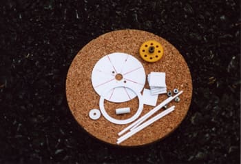
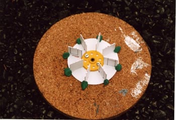
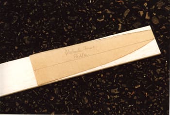
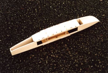
As the paddlewheels are likely to be the most troublesome part of this model’s construction, it seemed sensible to start with this part. They were going to follow the method devised for the Tipstaff model that is a solid inner disc, rectangular paddle blades with outer ring and spokes. Being more than satisfied with using styrene sheet, readily available in model shops, this was the material of choice. The sheet parts were cut from 1-1.5 mm (1/16 inch) sheet, the spokes need to be 2-3 mm (3/32-1/8 inch) square. The central tube needs to have an internal diameter large enough to accommodate the shaft that connects the wheels and worm gear. I used the body of an old ballpoint pen, cheap and strong enough. A couple of plastic gear wheels, with brass bosses and grub screws could be bolted to the inner discs for securing to the drive shaft. Mine came out of the scrap box and look like they came from an old construction outfit. These parts are shown in Photo 1.
The discs and rings were cut from plastic sheet using a cheap circle cutter. A trick I have learnt is to use the cutter’s blade in the opposite direction that you normally use for cutting. This means it acts to scratch a groove rather than cut one. I just find it easier and more controllable to use the circle cutter this way. Several light passes with the cutter ought to allow you to break the part out by flexing the sheet. The edges are usually rough but only light sanding is needed to clean them up.
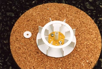
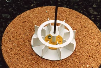
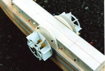
As eight blades were to be fitted to each wheel, I drew four equally spaced lines across the diameter. The centre of the discs must be drilled to allow the boss to pass through. Then a couple of holes can be made for the securing bolts. I strongly advise bolting the disc to the securing gear wheel; there is a fair amount of torque applied to paddles and glue might not stand up to any shock loading, like picking up debris or hitting things. Working on the paddlewheels becomes hard as the gear wheel prevents the inner discs laying on a flat surface. With the previous model an old cork tablemat was used to support the disc, a central hole being cut through the mat to clear the boss. Luckily I had not thrown the cork mat away and could reuse it. The paddle blades were glued to the inner disc using modelling clay to keep them square whilst the glue hardened, Photo 2. After this, the outer ring and central tube were added, taking care to position them correctly, Photo 3. The small outer disc is glued to the central tube, checking that it is level with the outer ring as the spokes have to bridge the gap between them. The paddlewheels are strengthened by having the drive shaft pass along the central tube and through a hole in the small outer disc. To ensure proper alignment I installed the shaft whilst gluing the disc in place, Photo 4.
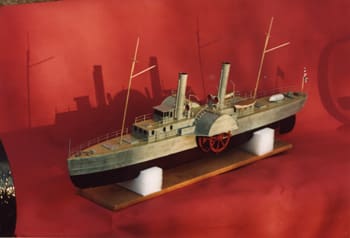
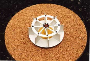
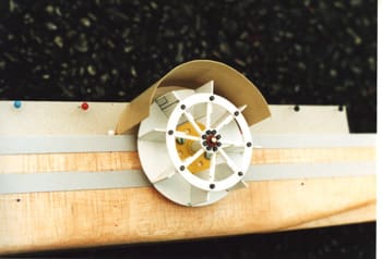
The final items can only be added when the glue has fully hardened. Spokes are glued between the central discs and outer rings. These greatly stiffen and strengthen the paddlewheels to ensure that a sound joint is made with blades, ring and disc. The final touch is just for appearance sake, the addition of ‘bolts’ to the disc and ring. These can be cut from plastic rod or tube and glued in place, Photo 5. These small items greatly enhance the appearance of the paddlewheels. Even more so after the wheels are painted, I sprayed them with red oxide primer and quite a few people have been fooled into admiring my ‘metalworking’ skills.
Hull construction
By making this a semi-scale model, the hull can be greatly simplified. With some skill, but perhaps cunning is a better description? the appearance whilst sailing hardly suffers. I decided to use the method of making a balsa framework, the hull bottom and deck separated by bulkheads, then covering the hull sides. This can produce a light and strong hull easily, quickly and cheaply. But, more importantly in this model, it allows you to accurately install the motor and drive line before adding the side sheeting, which is very convenient.
I will describe this section in a numerical sequence because, just like self-assembly furniture, the key to success is more to do with doing things in the right order rather than any exceptional skill.
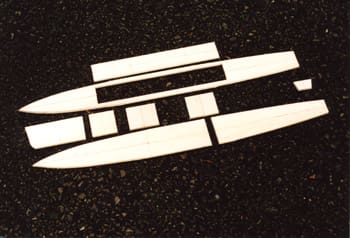
1) The hull parts were cut out of 1/4 inch (6 mm) balsa sheet. To ensure a symmetrical hull is made, I made a card template for one side of the bow and stern sections. This is used to plan the parts layout on the balsa sheets and, with care because it’s only cardboard, a guide for cutting around, Photo 6.
2) Having made a set of hull parts, Photo 7, they ought to be checked for accuracy and fit. I usually have a trial assembly and pin the parts together. It is not unknown to find some items the wrong size or out of square. At least correcting a fault is easier at this stage.
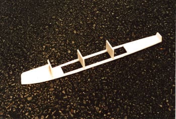
3) I suggest you start hull assembly upside down on a flat surface. It can make work simpler and quicker. Start by gluing the stem piece and bulkheads to the underside of the deck. Check for alignment and pin together, Photo 8. If they are not square then the final model might be noticeably bent.
4) The hull bottom pieces are added, gluing and pinning to the stem piece and bulkheads, Photo 9. The front and back pieces should join over bulkhead 3 and chamfering their edges will produce a neat gap-free joint. It is vital that the hull structure is left until the glue has fully hardened. Any attempt to rush building risks the structure coming apart in your hands.
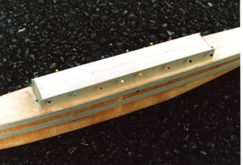
5) The support strips, which carry the drive shaft to the paddlewheels, were cut from some 1/2 inch (12 mm) square wood. I used pine for a little extra strength but, on reflection balsa would have been adequate. These two pieces need to be glued between bulkheads 2 and 3. I cut them slightly over length and sanded them back to give a snug fit.
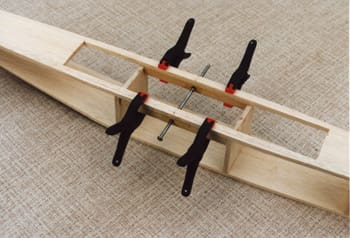
Before gluing in place, holes need drilling for the shaft bearing tubes; I used brass tubes that were a good sliding fit on the drive shaft. It is a good idea if these tubes extend outwards by an amount just greater than the thickness of the side sheeting. This will ensure that the paddlewheel bosses do not foul the hull sides when rotating. To ensure alignment, the tubes were fixed in place with epoxy, then the support strips glued into the hull and the drive shaft slid into place. After checking the shaft would still turn smoothly, everything was clamped in place, Photo 10.
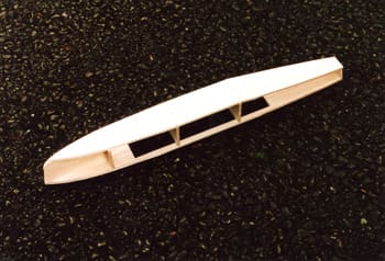
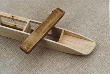
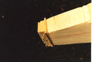
6) Again only after the glue has fully hardened can the hull be handled. The edges of the hull structure need sanding so that the side sheeting can fit flush and make a good glued joint. The only way I know to do this is with a sanding block that can cover the deck and bottom sheets simultaneously, Photo 11. The front edge of the stem piece must be shaped so that the side sheets can make a sharp bow.
Driveline installation
A worm gear requires that the motor is mounted perpendicular to output shaft. The worm gear on the motor shaft has to fit into the gear teeth without pressing too hard and thus creating excess friction. If, however, it is too loose then it is possible that the worm could move away from the teeth and drive be lost. This need for accurate alignment is one reason why it is so much easier to install the motor before fitting the hull sides in place.
The gear wheel in the set I bought was simply designed to be a push fit on to the paddlewheel shaft. I was going to just secure it with epoxy after cleaning and abrading the shaft but this would have been a little too permanent. If problems were to occur that required the dismantling and removal of the whole driveline then I might be well and truly stuck. The answer was to fit it with a boss and secure it to the shaft in the same fashion as the paddlewheels. Luckily the scrap-box could supply another boss with a securing grub screw which was then fitted into the gear wheel. The steel shaft was slid into the bearing tubes then the paddlewheels fitted to give just a little play (sideways movement). The rod was adjusted so that both ends extended by about 1/16 inch (1.5 mm) beyond the hole in the outer disc. This required the rod to be slightly shortened. Before refitting, the ends of this rod were rounded with a file to ensure that they would smoothly slide into place. The paddlewheels, gear wheel and rod were then refitted into the hull.
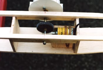
I decided to fit the motor behind the paddlewheels as this looked like it would make a neat layout for the electrical wiring. My first idea was to make a balsa block into which a motor mounting plate could be screwed, the height of the block being adjusted until the gears were correctly aligned. A trial run revealed that the securing screws would be hard to reach via the limited access through the deck cut-out. This is not good in any model let alone one where you cannot be sure it will work perfectly first time. I had to allow for changes in drive motors and possibly gears. Just looking at the model and trying different ideas eventually produced the final method. A ‘cradle’ was made from scrap balsa; see the plans and Photo 12. It was just wide enough for the motor to slot between the two extended side pieces. The motor could be held in place with elastic bands looped over the motor and secured to a length of dowel. Final adjustment was made by placing packing underneath the motor. Originally I used card strips for packing but then settled for some thin foam rubber which allows the motor a little movement without the risk of the gears moving apart. Thus, removing the motor is the simple matter of slipping the elastic band off the dowel and lifting it out of the mount.
Side sheeting
The hull sides were covered with 1/8 inch (3 mm) thick balsa sheets, with the grain running vertically. The sheets are cut slightly overlong and any excess can be removed later. It seemed best to start at the centre of the hull and work towards the bow and stern. The first pieces to be fitted had to have holes made to clear the bearing tube, Photo 13. The remaining pieces were added alternately to each side, this minimises the risk of distorting the hull, Photo 14.
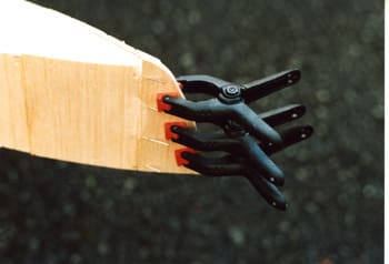
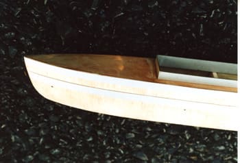
When it came to the bows I found it necessary to supplement pins with a few clamps, Photo 15. After the glue had fully hardened, the sheet could be trimmed back from the bow and the other side sheeted. The stern shape was built up from scrap balsa glued and pinned in place, Photo 16.
Finishing the hull
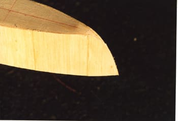
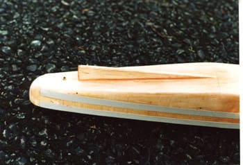
The side sheeting has to be trimmed back flush with the deck. I carefully remove the bulk of the excess with a sharp knife then use a sanding block, with medium/coarse paper, for the final levelling. The lower edges of the hull must be shaped into a radiused section; the cross-section on the plans shows what to aim for. Care is needed to avoid weakening the hull by removing too much material at this position. The bow has to have a curved form which can be achieved by sanding to match the side profile, see Photo 17, then blending into the hull lines. The stern block was sanded into a smooth well radiused shape which again blended into the hull lines.
You will almost certainly find small ‘steps’ between some pieces of sheeting. This can usually be removed by careful use of the sanding block. A medium grade of paper is best for this task, taking care not to excessively thin the side sheeting. At this stage the external surfaces of the hull have to be examined for any defects.
Small defects, such as pin holes, dents and minor gaps, just need filling. I use a tube of ready mixed domestic fine surface filler as it is easy to use, dries quickly and sands smoothly back to the balsa surface. To be honest, I also use it to repair non-structural defects in plastic and glass fibre models. If the defect is too big for this filler, such as a large gap, then a piece of balsa can be glued in place then sanded smooth.
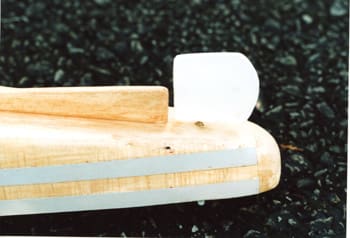
A skeg was fitted to the bottom of the hull, Photo 18. This was made from a piece of scrap 1/4 inch (6 mm) balsa sheet. It must be glued squarely to the hull bottom and be placed on the centreline. After the glue has set the edges of the skeg can be radiused. The skeg could be omitted but it does act to give the model more directional stability when sailing and offers some protection to the rudder.
Sealing surfaces
There are many ways to seal a balsa surface and I have no intention of being prescriptive. By all means feel free to use whatever method you feel confident with. I gave the hull several coats of Cellulose Dope, sanding between coats to produce a smooth finish. The first couple of coats were thinned, to ensure that the wood grain was well penetrated. The next couple of coats were normal, out of the can strength, and the last coats were made using a thicker ‘sanding sealer’. Now commercial sanding sealer can be bought at model stores but I usually make my own up. It is easy to do, just add some fine powder, like talcum powder, to neat dope. The aim is to make the mixture just noticeably stiffer to apply but not so stiff you have any difficulty spreading it with a brush. If you make it too stiff then just add a little more dope until the correct consistency is achieved.
As this is a model based on hard worked vessels, we do not require a perfect glass-like finish. You could go down this route but it runs the risk of producing a ‘toy like’ model that fails to capture the aura of the original whilst sailing. I’m happy with a toughened and sealed surface which can support the details to be added and the final coats of paint.
By the way, I also commit the crime of not bothering to seal the inner surfaces of a balsa hull. I never have done and have yet to regret it. My primary aim is to keep water out of the model with sound construction and sensible installation/maintenance of the internal items. Should a few drops of water enter the hull then the bare balsa surfaces can soak it up rather than letting it wash around the insides. Should more water get inside then the model has a flaw that needs correcting before it gets sailed again. And finally, even if the insides of a model appear to be bone dry after a sailing session, the model is left opened up (i.e., all removable hatches, decks, etc., taken off) for a day or two. As I said, this has always worked for me, even with a couple of submarine models!
The rudder
To make life easy, I had decided to have the rudder tiller above the deck and connect it to the servo with thin wire. With some careful placement of deck items and a lick of paint, this very non-scale feature is usually inconspicuous. It also allows you to make any adjustment or changes quickly. I was anticipating that some tweaking of the model might be needed to obtain a good steering response.
The rudder was made by laminating three pieces of plastic sheet together with the steel shaft embedded in the central piece. To ensure that rudder would never fail, the bottom of the shaft was bent through 90 degrees and the central lamination cut to accommodate this shape, see the plan. Some modellers rely on a straight shaft simply glued into the rudder blade, never the strongest method to cope with the abuse our models can be subjected to.
The rudder tube can be any convenient metal or plastic tube which is a smooth fit over the rudder shaft. Mine was a length of brass tube from the scrap box. Two holes were made through the deck and hull bottom for this tube, taking care to get the tube on the centreline and square to the deck. The tube was trimmed so that it protrudes slightly beyond the deck and bottom by about 1/16 inch (1.5 mm) and then secured with epoxy. It is worth checking before the epoxy sets that the rudder can move freely without fouling the hull bottom or skeg, Photo 19.
Card strips
The whole of the model’s superstructure, including the paddle boxes, is a one piece detachable item. This greatly simplifies the operation of any model as well as reducing the chance of damage when working on the model. This method requires a coaming strip to be glued around the inside of the deck opening, over which the detachable superstructure can fit, see the cross-section on the plans.
The coaming could be made from thin plywood but such strength is not really needed on this type of model. I used strips of card, about 1/16 inch (1.5 mm) thick for this job. Suitable card can be bought from art or stationery stores or, if you are cheap like me, it can be found in discarded packaging for free. After gluing the strip in place, it was pinned to ensure that it remained perpendicular to the deck. The card/deck joint was also checked for any gaps which might allow water inside the hull.
The hull looked a little bare at this point so I decided to glue strips of thinner card along the hull sides. This was to create the impression of the steel or iron structure that many of these vessels were built with. One strip was glued below the edge of the deck, the other above the waterline. I did not bother applying strips below the waterline as they would not be visible whilst sailing. The strips only ran from bows to the stern block, the compound curves around the stern defeated me. An impact adhesive was used to glue these strips to the hull sides. Such adhesives produce and excellent bond between card and sealed balsa but their ‘instant’ nature means that you have to get the card correctly positioned first time; there is no second chance, Photo 20.
The outer surfaces of the card coaming strips were sealed with a couple of coats of dope. A light sanding was needed between the coats to remove any surface roughness. The strips on the hull sides were also sealed with dope taking care to ensure that no gaps existed between the card and balsa. The ease of sealing and the smooth surface it creates for painting are also advantages of card.
Basic superstructure
To make sure that the detachable superstructure of any model is both secure and water resistant, I always build it over the deck coaming. Again I used card for the sides, the top being the piece cut out of the deck to make the access opening, Photo 21. Some care is needed to ensure that you do not stick it to the deck or coaming and it must be left until the glue has fully set.
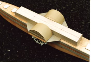
In order to build the paddle boxes you have to refit the paddlewheels. It makes sense to reinstall the whole driveline at this stage. To be honest I had not worked out how to construct the boxes before starting to build the model. Paper designs looked rather complex and not altogether strong enough. “Oh well”, the optimist in me thought, “something is bound to turn up when I reach this point” and it did. The boxes could be assembled using circular formers. The inner ones were cut from 1/4 inch (6 mm) balsa and stuck to the sides of the detachable superstructure again taking care not to stick it to the deck, Photo 22. The box was made from card which had been pre-curved to match the formers. This can be done by bending the card around a cylinder, but without creasing the card. Some experimentation to get the right size cylinder for the card used is to be expected. When happy with the shape, the card was stuck to the balsa former and left to dry, Photo 23.
The outer box former was made from card but on reflection, balsa might have been stiffer. This was then glued and pinned into place. The triangular box guards were also made from card glued between the front and rear edges of the boxes and the superstructure. The ends of the paddle boxes looked a little plain so I added some horizontal strips, Photo 24. The surfaces of the hatch and paddle boxes were tidied up, any defects corrected and three coats of dope, again sanding between each, were applied. I took particular care to seal the insides of the boxes and all the edges of the card. Operating paddlewheels can throw water all over the place and you do not want the card to go soggy on you.
I must confess that the model was given a test float in both the bath and garden pond with the r/c gear temporally fitted in place. Every new model is tested as soon as possible just to make sure that there are no serious problems before starting on the fiddly details. Suffice it to say that the model was stable and the paddles worked so it could be completed with some confidence.
Final appearance
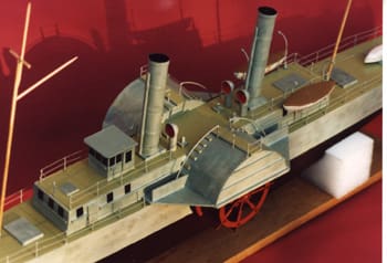
The excellent Osprey book offers the modeller lots of ideas for finishing this model off. Single or twin funnels, positioned before or aft of the paddle boxes, could be used. Some vessels had an enclosed wheel house but many appeared to have open steering positions.
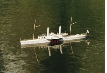
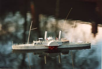
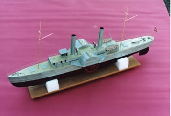
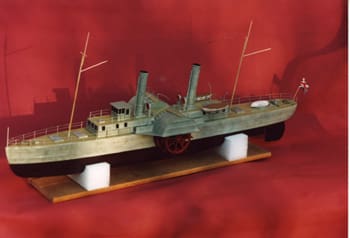
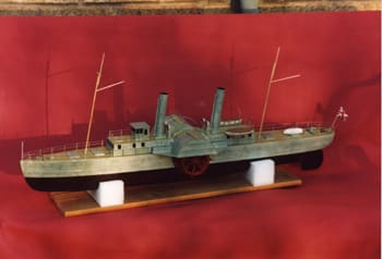
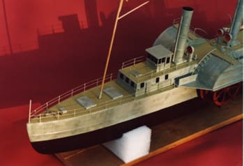
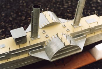
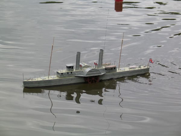
After playing with a few different ideas, a twin funnel and enclosed wheelhouse layout was chosen. Aft raked funnels, with mast following suit, appeared to be de rigueur on these vessels and it looks quite smart hence it was built into the model. To keep the top weight to a minimum, the funnels were made from card tubes; card was also used for the wheelhouse, hatches, etc. The masts were made from dowel and, would you believe it, tooth picks. In anticipation of some clumsiness on my part, the masts were removable, being stepped into aluminium tubes epoxied into the deck.
The most tedious part of the model, yet something I felt could not be omitted, were the railings around the edge of the deck and superstructure. They were made from brass wire found in my scrap box but copper wire is a good alternative. The stanchions (uprights for us landlubbers) were glued into pilot holes drilled into the decks, Photo 25. Thinner wire was used for the horizontal rails and joined to the stanchions by soldering. Rails were also added to walkways across the top of each paddle box. The ship’s boats were simply carved from soft balsa then sealed with dope. They along with other items such as the cowl vents were painted before adding to the model.
Painting
Many of the Blockade Runners were commercial vessels bought by the Confederate government and appear to have retained their original colour schemes. Thus, the Osprey book offers you the chance to paint the hull blue or even red! Later on, as the Union blockade became tighter, the value of subdued colours appears to have been realised and grey became popular. I chose to use a light grey colour which was in keeping with the character of these vessels and, at least over the distances we operate our models, probably makes the model more visible. A little ‘dirtying up’ of the hull and superstructure was carried out by lightly adding patches and streaks of a darker grey. This effect is almost invisible, unless viewed close up, but adds to the character of this model.
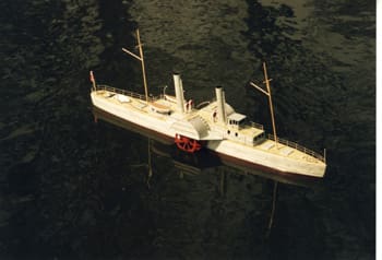
The hull below the waterline was painted red but not the bright red that some modellers use. This can be seen far too easily in the inch or two of water that our models operate in and totally fails to look realistic when sailing. I mixed equal amounts of black and red to create a very dull red which is all but invisible whilst sailing. The decks were painted with one of those authentic military paints that ought to represent weathered planking. The paddlewheels, as mentioned earlier, were sprayed with red oxide paint, a dark grey may be more realistic but it’s nice when spectators can see all the work you put into making them.
Gloss paints were used on the hull. This is usually unrealistic on scale models but gloss is much tougher than matt paints and who has not scraped a model whilst sailing at some time or another? The shine was taken off this model with a couple of light coats of satin varnish.
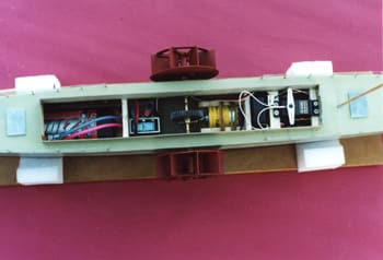
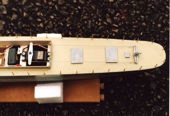
Installing the r/c gear
The paddlewheels were reinstalled along with some oil in the bearing tubes and a spot of grease between the hull and wheel bosses. The drive battery, a six cell ‘sub C’ NiCad pack would fit into the compartment between bulkheads 1 and 2. The speed controller went into the next compartment between bulkhead 2 and the driveline. I was using an ASTEC HFR15 model but most commercial controllers should fit. This model does not require much in the way of power so your speed controller should not go up in flames but do use one with good slow speed operation. Some of the r/c car controllers can be a little too insensitive when used in a low powered boat model.
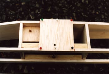
The rudder servo was fitted into the rear compartment. Balsa rails were glued to the underside of the decks, running across the access opening. They were spaced to allow the servo to slide in-between the rails and be secured by screws through the mounting lugs. This left just enough space between the servo and bulkhead 3 for the receiver to drop into place, Photo 26.
The tiller arm on the prototype was made from a spare servo arm to which a securing screw fitting had been added. Suitable commercial items ought to be available at hobby stores. The linkage between the tiller and servo arms was to be a double one made with fine wire. This can be a very positive method as both wires should be in some degree of tension and the wire is almost invisible. Reliable operation requires that both arms remain parallel at all times, Photo 27. If you prefer then a single stiff wire could be used, paint it grey and you will hardly notice it. Either way a small cut-out in both the coaming and removable hatch will be needed to clear the wire link(s). Any bare card surfaces exposed need resealing with a couple of coats of paint.
The receiver’s aerial wire could be run around the superstructure or up one of the masts. I prefer to use a fine detachable wire to make a vertical aerial to obtain the best possible radio signal for the receiver. This is connected to the original aerial wire via a flying lead and small plug and socket, keeping the total length the same as the original aerial. Such fine wires are usually invisible when sailing and give an ‘out of sight’ radio range. What ever you do with the aerial, do not leave it coiled up inside the hull.
Pre-sailing checkout
The model had a final ballasting trial in the garden pond. Strips of lead sheet were added to either side of the battery pack and in the rear compartment under the servo and receiver. This brought the model down to the desired waterline in a level trim. A stability check was made by rolling the model until the outer edge of the paddle boxes were in the water. Upon releasing the model it would spring smartly upright and oscillate a couple of times before returning upright. Experience with many other models suggests that this means it will have more than adequate stability. The weight of the model was 4.25 lbs (2 kg).
Before any sailing trials could be carried out, all the ballast had to be secured. I used a latex based adhesive, it forms a strong enough bond to prevent the ballast moving whilst sailing which would otherwise affect the model’s trim and stability. Should you ever need to remove the ballast, then the latex can be pulled apart by a steady force without damaging the model. Alternatives to secure the ballast could be the rubbery types of sealant. Whatever you use, remember the aim is to stop things moving whilst sailing, not bond them permanently in place.
Sailing trials
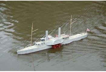
Even though the model was completed in the winter months, the gods favoured me with a bright and sunny day with only the lightest of winds for the first sail. Everything checked out OK so the model was carefully lowered into the water and the throttle stick slowly advanced and the rudder applied to move away from the bank side. The first surprise was that the rudder was effective as soon as the model moved. After a few minutes sailing at all speeds it was clear that poor steering was never going to be a problem. This can be attributed to the large area of the rudder but another two factors appear to be equally important. The first is that the rudder extends well below the hull. This was done to avoid having the entire rudder in the sluggish ‘boundary layer’ of water that forms around any body moving through a viscous fluid. The second factor is that the rudder shaft is set back from the leading edge of the rudder. As a result, when the rudder moves, the leading edge swings away from the skeg. I believe that this results in the rudder being able to deflect more water. Whatever the reasons, this model turns just as well as many that have a propeller ahead of the rudder. Turning circles down to about 6 feet (2 metres) in diameter could be achieved in both directions.
A second delightful discovery was that the model would steer just as well when going astern. Without the aft rake in both funnels and masts it might have been hard to tell if the model was going ahead or astern at times! To round off the sailing characteristics, the model was very stable with little heeling during even the tightest of turns. So much for my worries about the narrow beam.
This first sailing session might sound to have been perfect but one problem did appear. I timed the model over a measured length and found that its top speed was only 1.3 ft/sec (0.4 m/s). This was about half of what I had been planning for. So, I returned home a happy but slightly puzzled man.
Problem solving
My first thoughts on the lower than expected model speed was that the worm gears were to blame. I had originally planned for using a 30:1 reduction ration whereas the gears used had a 40:1 ratio. Checking the rotational speed of the wheels did indeed show them to be turning at a modest 125 rpm but this was still slower than the higher gear ratio ought to have produced. As the driveline was still turning over smoothly I started to test the electrical items. It did not take long to discover that my six cell NiCad pack was in fact behaving like a five cell one and only producing 6 volts.
Replacing this pack with the genuine item, the wheels sped up to around 165 rpm. This was better but still short of what I felt was needed for dynamic realism. A higher speed motor could have been substituted but I tried adding three extra cells and was rewarded with a healthy 260 rpm. To be honest the gears were making a frightful racket but everything was holding together.
Back to the water
On the second trial I started with the extra cells on board. At part throttle the model behaved just as before, stable with predictable handling and great fun to sail. Full power produced a brisk acceleration up to a speed of 2 ft/sec (0.6 m/s). This looked more impressive, still a shade less than I’d planned for but the noise was awful. Nothing in the driveline failed but I could not justify all that noise pollution.
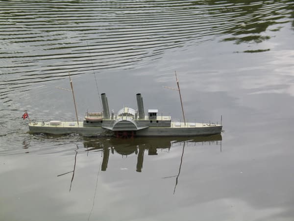
The model was recovered and the extra three cells removed for testing on 7.2 volts. The top speed was down to 1.5 ft/sec (0.46 m/s) but so, thankfully, was the noise. I settled down to relax and enjoy the model. After an hour, it was clear that this model can be handled in much the same way that a conventional single propeller and rudder model can. The only obvious drawback was that the propeller can start a model turning from rest before any significant moment has occurred. The paddles have to get the model moving before the rudder has any ‘bite’. Thus, manoeuvring in tight spaces just requires a slightly different technique with paddles. At the end of this longer sailing session I was very happy with the model’s handling and appearance on the water. Response to rudder and throttle commands was immediate and the model would hold a course remarkably well. The lower speed than originally anticipated proved to be no real problem as the model sails with the characteristic humps in the wash aft of the paddles. It looks and ‘feels’, in the way that working models act on your emotions, just right. As a final bonus, very little water gets splashed onto the decks from the paddle wheels and the insides have remained perfectly dry.
Conclusions
My second attempt at a paddlewheel r/c model, despite being very different from the first one, has proven to be very successful. Sailing it is a totally stress free but nonetheless an absorbing activity. The use of a single worm gear set has a lot to commend it, simple, cheap, compact and efficient. The latter is reflected in the modest current drawn when sailing, less than 1/2 amp. This means that even the cheapest of six cell NiCad packs should give you a running time of 2-3 hours.
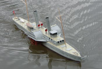
The character of the Phantom model when sailing always seems to attract favourable comments from non-modelling spectators. It might not be fast or large but the visible paddlewheels do give the aura of ‘life’ that some models can lack.
Eventually the reason for the model’s lower than planned speed was discovered. In the initial calculations I had assumed a figure of 25% for the slip between the wheels and model. Reviewing these figures it became clear that 50% slip is a much more realistic value. This is something to remember when I build my next paddlewheel model!


