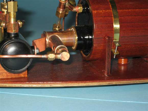
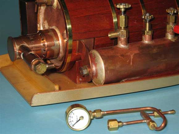
Pic 1: Gas tank and burner fitted fairly closely together. Pic 2: Gas tank and burner fitted fairly closely together in an alternative installation. Pic 3: General arrangement of tanks and burners. Pic 4: Steam plant on a removable tray. Pic 5: Steam plant installed in a small launch. Pic 6: An older system, no longer used. The original article on gas tanks and burners was published in the June 2005 issue of Model Boats, but it was actually started early in 2004. Since then various alterations have been made to the system, some ideas have been scrapped and some new ones added. The very first of my ideas started to take shape more than 20 years ago. One of the newest ideas is much more useful than any of the others and this is to fit a pressure gauge on the gas supply line to the burner. Various people have called me obsessive (put very politely) about another aspect of the models and that is the idea to make as much as possible to be removable. This does make the experiments relatively easy to accomplish without destroying anything on the model. (Back issues or photocopies of the original article if required are available from the address given on the contents page Editor). Enjoy more Model Boats Magazine reading. Click here to subscribe & save. 1. Heat ShuntThis was explained in the original article and many arrangements have been tried, it can be seen in Photos 1, 2 and 3 that the gas tanks are now very close to the rear end of the burner because this keeps the length of the shunt as small as possible. As long as a spanner can be fitted down the gap then everything can be kept very small and neat to fit into a small vessel, see Photos 4 and 5. The length of the smallest tray is 11 inches and the launch it fits into is 21 inches long with an overall weight of less than 5 pounds. 2. LayoutOver the years some set-ups have worked better than others, see Photos 6 and 7 of the older system and it is slowly dawning on me that one arrangement keeps cropping up which is shown in the first photos. This places the gas tank adjacent to the burner and fitted across the length of the boat. Maybe another layout will be devised one day, but this is the one I always try to fit because it works extremely well. 3. Tank Clamp BoltOriginally I made a cradle in to which to drop the tank and then glued the tank in place. This made the tank non-removable, but now at the base of the tank I always fit a bronze bush, silver-soldered into position. The thread obviously does not go into the gas space and the thread size is typically 4BA or 6BA. Please See SKETCH A of Little Emmys Gas Tank and also Photos 8 and 9. This bolt is not intended to try to pull the tank down viciously onto its cradle. The bolt length can be filed so the tank is just held down on to the cradle without any slop and all this needs is my usual weapon, commonly called a file. This also means that a particular gas tank can be easily removed from one boat and fitted into another, however if any tank is removed on a frequent basis and swapped around then possibly some sort of a large knurled nut fitted with O rings may be better than frequent usage of a small spanner on very fine-threaded components. 4. Pressure GaugeWhy didnt I think of this a hundred years ago? So simple to check, and so very easy to see when something is wrong. See Photo 10. The gauge is fitted to monitor the gas supply line to the burner, so when the burner is running normally at its correct supply pressure it will require a certain pressure to be supplied from the tank. The smallest pilot burner I have made only needs about 10 P.S.I., but some of the larger jets may need about 30 P.S.I. Please note this will require more pressure to be delivered than is available from a cold tank, so it aint going to work! There is one exception to this idea and that is to feed the burner with liquid gas. This method was published by Peter Arnot in Model Boats quite a few years ago. The best size gauge found so far reads 0 to 60 P.S.I. and is 3/4 inch diameter. Maybe even 1 inch diameter could be fitted if there was no worry about hiding a large gauge under the deck. With a little thought, the gauge will show many things:- Assuming the tank is too cold, then the pressure in it will never be high enough to lift the gauge to its proper reading; perhaps the tank is empty in which case it will show zero P.S.I.; maybe the burner is clogged, so the gauge will show full pressure, but there will be no gas coming out the end. One thing that was accidentally discovered was the dreaded whistling gas flame. This can become very loud as the burner tube hits resonance with only a very small, critical amount of gas flowing along it. The gauge will also show if the tank is far too hot on a summer day and hence too much pressure. This means that as soon as the valve is opened by a fraction of a turn, then there will be too much gas flowing, so the flame will either singe all the paintwork or more likely it will blow out, and this usually happens in the middle of the pond. If it is a hot summers day, then the installation will probably run with the heat shunt removed, see Photo 11. Again this is easily visible on the gauge. Perhaps not for a completely brand-new commercial boiler and gas-tank arrangement with a current guarantee, but I would fit a gauge on any vessel because it is so useful, see Photo 12. Obviously all the pipe joints are cone unions or silver-soldered with Easyflo 2. I admit I am a dinosaur, but I still prefer the silver-solder with cadmium, because it flows much better and produces a smooth fillet, especially when going round the end of a boiler or gas tank. 5. Gas MatchWhen the original article was written, there were not many of these available locally, but now they are easy to purchase from local supermarkets as a disposable item. £1.29p for a pack of three and they are very useful. 6. Tank coolingThis was also detailed in the original article and it is very important. Once you are aware of the problems caused by a cold tank, then it becomes second nature to get round them. As gas is taken from any canister it will expand and loses heat in the process. Ultimately the canister freezes and it is no use until it is warmed up again. The best method is to fill the tank early and let it warm up slowly, but if in a real hurry then a small duster soaked in warm water and laid on the tank would do the trick. If the water is not hot for your hand, then it will not overheat the tank. This may sound drastic, but the effect can be checked on the pressure gauge, and there is no need to go mad and try to boil the tank. Just do it enough to make the tank not feel icy. If anyone is worried about the safety aspect of doing this, then remember that the tank is silver-soldered and pressure tested to several hundred P.S.I. – normal running pressure in the tank is typically 30 or 40 P.S.I. On a really hot summer day this may be 50 P.S.I. Again this can be seen on the pressure gauge or judged from how far open the gas valve needs to be.
|
|
Pic 7: The older system, no longer used, but with pipes and gauge removed. Pic 8: The cradle for the gas tank. Pic 9: The mounting bolt and nut for the gas tank. Pic 10: Pressure gauge is useful. Position it so that it is easy to see. Pic 11: Heat shunt swung clear of burner. Pic 12: A pressure gauge is easy to fit. Pic 13: An example of identification marks stamped on any end of tank body, before any silver soldering. Sketch A: A diagram of the parts for the gas tank for Little Emmy. Sketch B: A schematic diagram of the parts for the new burner for Julie Anna. Sketch C: The dimensions of the new burner for Little Emmy. 7. Gas ValvesVarious people have said to me that three valves are far too much work and they have their own system with a home-made combined fill and vent system. Regrettably I have been unable to coax any details from the people concerned, so I continue to fit three separate valves because they work and can also be used to transfer the small amount of gas remaining after a run, into another tank, thus not wasting gas or storing it over winter. 8. Domed and flanged tank endsThese are now used for all the gas tanks instead of several other methods that have been tried, please see Sketch A again. Most times the ends are 2.5mm copper sheet using a hardwood or mild steel former. If only one pair of ends is to be made, then hardwood is perfectly satisfactory, but if the size of end may need repeating, then a mild steel former is best, but it will need more work. If any identification marks are needed for the gas tank these can be stamped into one end of the copper tube BEFORE any silver-soldering is carried out, see Photo 13. Being stamped at one end, means the marks will be under the silver-solder where the flange slides into the tube when it is finally completed. This does not detract from the strength of the tank nor does it distort the copper. If the stamping is carried out after silver-soldering when the copper is very soft, it will make quite a mess, believe me. 9. Make it removableYes this was firmly mentioned in the original article and no excuses are offered for repeating it. On several occasions in the past few years I have been asked to mend steam boats for other people. Some of these have had a rigidly fixed steam plant. Oh dear, what a nightmare! Open launches are no problem because everything is fairly accessible, but down in the black depths (yes, interior painted black) of a tug or cargo boat, the nightmare is particularly bad. I am not even sure if I was capable of fixing a particular problem, but there was no way to reach the gas burner in situ on that model. Eventually I gave up and asked the owner to remove everything for me. He had fitted the steam plant first and then put the deck in place afterwards and he did not appreciate my offer to use a power jigsaw on the deck to make a large hatch for removing the steam plant. 10. Gauze or Ceramic?I still continue to prefer stainless steel gauze to make the burner elements. Please see Sketches B and C. So far I never found any pieces of ceramic which survived for any extended period of time. Maybe I have asked the wrong people, or I have used it incorrectly? The original gauze size of 30 holes per inch is still the preferred size and will continue to be used, since it not only works well, but also because I was given a piece by a kind person at an exhibition in Portsmouth. I acquired the burner gauze and I was also given some small circles of ultra-fine gauze to fit the space drilled in the rear of the burner jet. This was the finest mesh I have ever seen, and is fitted as a filter to keep any bits of muck out of the jet hole. Model engineers and model boaters are very helpful people on these occasions. 11. Gas Jet suppliersWhen the first article was written I put the name of Bruce Engineering as a supplier of Calor gas jets. Since then, they have become part of Polly Engineering and reside in Long Eaton, Nottingham. 12. SafetyWhether or not it stands out in either of these two articles I do not know, but I do try to work carefully and have only changed one parameter at a time in any of my experiments. So anything written here is not just thrown in haphazardly and they should work. Remember, liquid gas needs care to be used safely, so do not light a cigarette at the same time as filling a gas tank. Also make sure no-one in the vicinity is handling anything flammable when you fill a gas tank. The few necessary safety rules soon become second nature. Everything written here and in the other article is intended to make sailing a steam boat as easy as possible. The idea is to arrive at the pond, get steam up and go. I would rather be using spanners and screwdrivers at home, not with everyone watching and most times it works. Happy sailing.
|
More Gas Tanks & Burners
Enjoy more Model Boats Magazine reading every month. Click here to subscribe.
Article Tags: