Monitors, like their predecessors the Bomb Ketches, were not designed to fight other ships but to bombard land targets from the sea. Many people are aware of the large monitors of WWI and WW2 with guns as large as 18ins. They shelled all sorts of targets from heavily fortified forts and coastal batteries to troop positions. Imagine the effect of a 15in, one-ton shell landing in your trench! But in 1915 nineteen smaller vessels were built with guns from old cruisers. The M15 class mounted a 9.2in gun, with smaller AA weapons, whilst the M29 class carried two 6in turrets and a single AA gun. They were built in various yards from William Gray at Hartlepool, M15, to Workman Clark of Belfast, M33. As built there were many variations. Most were steam driven with two shafts, but some were diesel driven. Four ships had four screws! M23 -28 had a 7.5in or 6in or 4.7in gun in place of the 9.2in main gun, and the secondary armaments varied – though I can’t really understand how a vessel of this size fitted with a 4.7in gun could be classed as a monitor! I have four pictures of these ships in my ‘library’ and all are different! One has washing hanging out on the superstructure! So we have some leeway whilst building a semi-scale model.
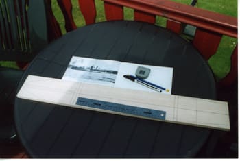
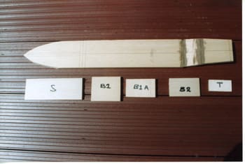
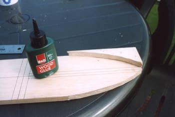
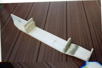
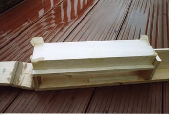
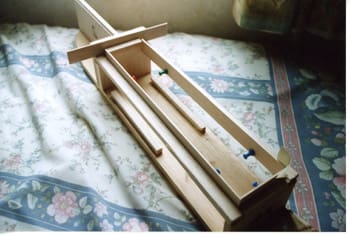
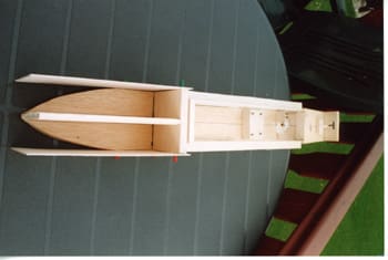
Pic 1: Marking out the base from the plan. Pic 2: Hull bottom with ‘V’ cuts and filled. Bulkheads cut out. Pic 3: Starboard bow cut-out can be used as a template to ensure a similar shape for the port side. Pic 4: Bulkheads, transom and stempiece fitted. Pic 5: Inwales and battery guides fitted. Pic 6: Motor mount and prop shaft held in place with Blu-Tack initially before securing with filler or epoxy.
The model
I decided on a diesel driven version as funnels and winches seemed simpler and it would save fitting coaling scuttles along the side decks! (M34 wasn’t actually built.)
Enjoy more Model Boats Magazine reading in the monthly magazine.
Click here to subscribe & save.
The model is designed as an easy-build project that I hope the ‘first-timer’ will be happy to tackle and yet as it is built to a specific scale, 1:72. Lots of inexpensive fittings, ship’s boats and crew can be made, or purchased, to make the on-the-water look quite impressive, if that is the way you want to go.
One thing about the small vessels of that era is that they were quite simple designs themselves, little or no shear, straight stems and basic rectangular superstructures, often built along merchant ship lines by yards that had only ever built merchant ships before the conflict. So study the plan, the article and the photos and study the plan again!
Hull
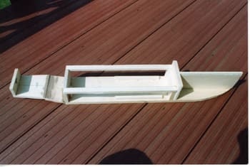
The model is based on a length of 900 x 100 x 12mm balsa. I chose the hardest piece I could find in the shop, as this is needs to be the strongest part of the model. A 750mm length is cut to form the hull bottom. The shape is transferred from the plan and cut out. At the point indicated on the plan a shallow ‘V’ is cut across the hull width, try not to cut right through but it does not matter. Fill the ‘V’ with adhesive and prop up to match the angle on the plan. When fully dry a second cut is made across the bottom as indicated and the aft section forced horizontal again and this section propped up level on anything to hand. The ‘V’ created needs to be filled with plastic wood, filler, etc., and left to set.
Next is the stempiece. The three main bulkheads and transom are cut to shape from the plan and glued in place. If necessary pin from underneath whilst the glue sets. If tapped right home the pins could be left in place and covered by the paint job.
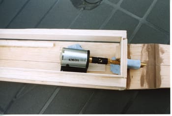
The next job is the first ‘technical’ job and best done at this stage. The after bulkhead helps to support the prop shaft tube and a hole needs to drilled through the bulkhead and the hull bottom to facilitate this. I have an old long bladed terminal screwdriver whose end is so damaged that it makes a good boring tool, and I tend to use this to make a pilot hole at the correct angle. The holes are then opened up to match the shaft tube size you intend to use. I used a 125 x 4mm tube with matching shaft. If you use a larger or smaller diameter shaft you need a larger or smaller hole! I know, I know, but this might be someone’s first venture into model shipbuilding.
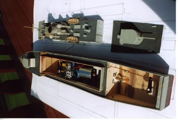
The main motor/bracket and coupling needs to be mounted inboard, on scrap balsa, and the prop screwed onto the shaft. You can make the holes a little oversize and Blu-Tack everything in place until you are happy that everything is inline and that the motor and prop rotate freely without fouling the hull bottom. Once happy slowly remove the Blu-Tack and replace with filler or epoxy to secure the shaft tube and make the hull watertight, and secure the scrap balsa supporting the motor bracket. Once the filler has set the motor/bracket/coupling assembly can be removed and the prop and shaft withdrawn to be refitted later.
A hole now needs to be drilled vertically to take the rudder tube. A scrap length of brass or plastic tube needs to be glued in place (e.g., two-part epoxy). As shown on the plan the top of this tube needs to be above the waterline – otherwise you are building a submersible! I drilled and fitted a block of scrap balsa over this tube to support it.
I know the temptation is to push on with the main hull build but one more step is advisable. Make the rudder and fit its servo, linkage and tiller arm. The rudder was made up from plastic tube for the stock. A short length of wire is inserted in the tube and a short section bent at right angles to help support the blade and give positive movement. Imagine the blade spinning on its shaft as you try to steer round a regatta course! The blade is made up by laminating rectangles of scrap plastic to make a sandwich, gluing and filling, see photos. A hole needs to be drilled in Bulkhead 2 to allow the rudder linkage to pass through to connect the servo to the tiller arm.
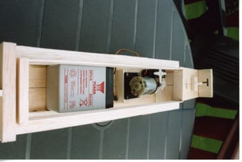
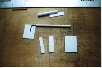
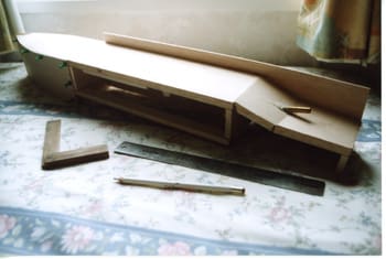
Pic 7: Battery, motor and servo plus rudder tube installed. Pic 8: Fabricating the rudder assembly. Pic 9: Main superstructure ‘tray’. Pic 10: Coaming for superstructure ‘tray’ to sit over. Pic 11: Gluing balsa sheet hull sides at the bow. Pic 12: Fixing main hull sides. Pic 13: Planking continues.
On with the hull build
The cutouts on the top of Bulkhead 1A and Bulkhead 2 will support the two inwhales. The two lengths of 15 x 6mm are cut to size to fit your model, it could be slightly different from the plan! Mine was!
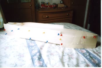
At this stage I suggest you fit your battery guides. These are two lengths of 6 x 6mm balsa strip to keep your battery on the centreline. Place your battery/pack on the centreline butted up against the after side of bulkhead 1A. Cut the two lengths of 6 x 6 to fit from the bulkhead to run aft as far as the motor mount position. Fit them tight alongside the battery/pack and glue and pin in place.
These guides will allow you to move a major part of your ballast to get the correct trim. At a later date Blu-Tack your battery/pack in place when you have the sorted out the trim. Remove the battery/pack. This last exercise could be done whilst the motor is still in situ – I forgot!
It is now time to begin ‘plating’ in the hull sides. I found the easy-way was to do it in two parts. Two lengths of 100 x 2mm balsa were cut as per plan, cut slightly over size; it’s easier to trim back than lengthen! Using the machine-cut end of these off-cuts glue these to bulkhead 1 with your cut end going forward to glue to the bow. See photo.
The hull sides should protrude above the stempiece and bulkhead just enough to allow the deck to be fitted between the sides, not over them. Now invert the hull and support the after section so that the forward section is clear of your work surface. See photo. The two lengths of 100 x 2mm balsa sheet are now glued in place. The machine cut end is butted up to the forward sides and glued to the hull bottom, inwhales, bulkhead 2 and the transom – leaving enough proud of the inwhales, bulkhead and transom to cover the thickness of your decks. Pins and masking tape can be used to hold the sides in place whilst the glue sets.
With the hull inverted the excess will be sticking up proud of the hull bottom. When the adhesive is thoroughly dried this excess needs to be trimmed away. You should now have a large rectangle in the centre of your model.
Using off-cuts of balsa, card or plastic sheet, three coamings need to be cut to size as per plan. These are glued to the insides of the inwhales and the after bulkhead. To get the superstructure to fit properly and give a watertight fit, a final piece of balsa has to be fitted. This is cut to fit between the two fore and aft coamings and wide enough to fit across bulkhead 1A and between the two coamings. The plan and photos should explain it. It is glued in place using a spacer made up of the same thickness as the superstructure material you are using; balsa, ply or card. See photo. Excess height will help to hold the superstructure in place.
Pic 14: Red oxide card applied to superstructure sides. Pic 15: Building up the turrets. Pic 16: Superstructure assembled and in position prior to final decking. Pic 17: Plan view of model showing ease of access.
Superstructure and deck
The main section of the superstructure is pretty simple, a rectangular, inverted tray. It needs to be built to fit the coamings you have created, not just built from the plan! Cut the four sides slightly oversize and carefully cut and fit using masking tape to get a nice tight fit. Once happy, glue scrap balsa into the four corners and across the gap between the two sides to strengthen your rectangle. Make sure you do not fix it to the deck or coamings! Once the adhesive has set check your rectangle will lift off and fit back again snugly. The deck now needs to be fitted. A piece of oversize balsa, card or ply is glued across your rectangle whilst it is still in situ. Again give your adhesive time to set fully. Remove the lower superstructure, invert, and trim away the excess deck material. Add more adhesive and scrap balsa if you wish inside the superstructure.
You now have two parts of your model, the hull and the basic superstructure which can be worked on separately. The hull needs the decks fitting, the lower superstructure needs finishing and the wheelhouse and upper bridge building.
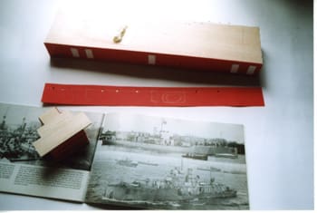
I built my superstructure from balsa and covered the sides in thin card to give a better surface for painting. I chose ‘red oxide’ card so that any dents or scratches merely look as though it is rust or the crew are touching up with primer before painting! The deck is not covered as it gives a non-slip surface appearance. The simple rectangular doors were cut from the same material and fixed in place. Hinges and handles are up to the individual modeller, but in my experience, even on simple models, the time spent adding any little detail adds greatly to the final overall appearance.
An aside!
Practically all RN vessels have masses of small items in view and this era was no exception. These little additions; ready-use lockers, meat safes, tank vents, etc., can turn your first model into something that looks almost ‘scale’ (stand-off on the water at least) rather than a toy. And that is my aim; the under water sections, flat bottom and deep draft are not scale but using inexpensive scale fittings and a little effort a nice stand-off model can be produced. Anyway back to the building.
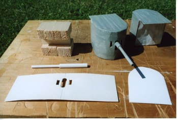
A study of the plan shows a simple wheelhouse. This can be built up as a solid block or like the lower superstructure, i.e., a set of bulkheads to replicate the plan, again faced with thin card or plastic. I cut a piece of 6mm thick balsa sheet to match the floor plan. Balsa sheet sides were then cut and fitted around the base block. I cut a length of card to the right height and long enough to wrap right round the whole wheelhouse and glued in place. Strips of thin balsa are then laid across the top of the wheelhouse to form the deck of the upper bridge.
The upper bridge seems, in my shots, to be unprotected with only canvas dodgers fitted to the railings. The more experienced could fit stanchions and canvas covers, etc. For an easy build I cut thin card to the right height and long enough to fit round the upper bridge and covered this with standard masking tape to replicate canvas. You could glue beheaded pins at regular intervals and add some thin fuse wire horizontally along the card before fitting the masking tape. It gives the impression of rails behind the canvas. As the mood took me I worked on the hull or superstructure. Paint one or add details to the other.
The funnel was cut from plastic tube – own brand denture cleaning tablets at 39p; I had the cowl vents in my scrap box, but these are readily available from model shops or mail order; and I had ordered the 1:72 Bridge Set Pack 1 from Sirmar. These fittings are intended for the WW2 Corvette but for a modest outlay you get ship’s binnacle, compass repeater, voice pipes, searchlights and signalling lamps and about 18 lockers of different shapes and sizes; enough to satisfy our simple WW1 vessel.
I had also ordered a couple of 16ft ship’s boats (to scale of course!), anchor winch, life rings, some rope reels, a packet of port-holes and the prop tube and shaft from Model Dockyard of Truro. Once you set up a Customer ID a quick phone call has the items on your doorstep within days. (Only one boat turned up with this order, but after a quick coms exercise the second boat arrived!) They stock fittings from different manufacturers so you can select items to suit your budget, i.e., you can get a 16ft dinghy for £1.92 or £6.58! Of course the expensive ones, from Quaycraft, are the best you can buy, but probably out of our range for this model, but the choice is yours.
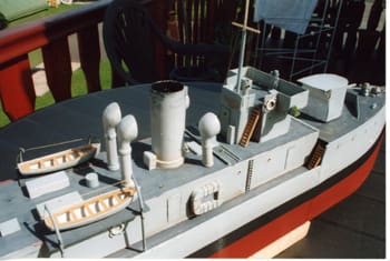
Pic 18: Close up of upper deck and wheelhouse.
Turrets
The plan gives an exploded view of the construction of the turrets, basically a block of balsa with a wrap-round front shield. The gun opening and sighting ports were cut first and the shield, thin card, is glued to the balsa block. It is then inverted and glued to card. When the glue is set excess card is cut away to form the shield’s top. This overhangs by about three feet. This in turn is supported by metal rods at either side, pins or thin wire. The barrel should be fairly easy, using the plan and photos. One of the shots I have clearly shows a canvas spray dodger hanging down at they rear of the gun shield, protecting the breach mechanism, etc. This seemed an ideal easy-build chance, so again masking tape was put to use covering the whole rear of the gun house and painted matt white. The more experienced could fully detail the inside of the shield. I suppose a 1:48th scale 4in gun becomes a 6in gun at 1:72 scale, as long as the shield is as per plan! The other gun is from scrap as per plan.
Back to the Hull
I covered most of the hull, mainly above the waterline, with aluminium tape from Halfords. It strengthens the balsa sides and gives a better surface for painting, but is optional. Living in a mobile home my paints and varnish are generally water-based, but for the lower part of the hull I used Halfords aerosol red plastic car primer; outside the van. I fitted an ‘A’ bracket to the shaft tube but this again is optional. All the shots I have are in monochrome and appear rather dark, so I erred towards darker shades of grey. But what I do is use slightly different hues on different items, lockers differ from the ship’s boats, vents from guns; it has the effect at distance of bits of the clutter standing out and giving some depth to the model.
At this point card, balsa, ply, plastic, decks were cut to fit at the fo’c’sle and quarterdeck. Once happy with the fit they were strengthened underneath with strips of balsa glued at right angles to the deck. Keep checking that the deck will fit. These could be fabricated as soon as the hull sides have been fitted and worked on when the bit of free time appears. The fo’c’sle has hawse pipes, winch and anchor chains, breakwater, gun, rope reels, lockers, vents, etc., a project in its own right. The quarterdeck is much the same. With the hull fully painted I gave it several coats of varnish, inside and out!
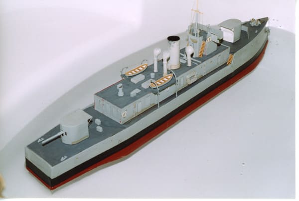
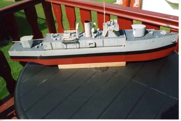
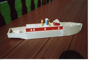
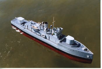
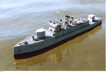
Pic 21-22: Finished model.
Finishing off
So really we are at a stage of finishing off. The hull, superstructure and weapons have been made, all the fittings from the anchor winch forward to lifebelts at the stern; and if you refit the battery, motor, coupling, shaft and prop your model can go into the water. With the Rx and ESC in place, Blu-Tacked on top of the battery, bath trials can take place. The main reason for the exercise and the fact that we have not yet fixed down the decks is to check the trim and waterline; you may need some additional ballast forward or aft. Depending on the size (weight) of the battery/ battery pack you use will decide whether additional ballast will be needed to get the model down to the correct waterline. I have deliberately increased the draft of the model to get the heaviest items at or below the water line and make sure she does not ride on the water like a cork. I needed some additional ballast mainly dead centre to get the trim right.
The lower mast is from plastic tube and allows the Rx aerial to be fed up as far as the yardarm. Things like fairleads and bollards can be purchased from the carousels of good model shops and fitted as and when. You can get your model on the water and sailing pretty quickly with this sort of project, but you can go on and on adding detail throughout the dark winter months. There is nearly always something you can add to a model. Crew at action stations, crew at passage routine, crew at cleaning stations! Anyway I am going beyond the remit of this project, if it is your first model it is not difficult, and you will not waste a lot of money if it all goes wrong.
On the first outing to the lake it was quite windy and I was glad of the deep draft and additional ballast. I have also increased the rudder blade size on the plan to give better control. (I have not yet made a fitted a larger rudder!) Total model weight is about 2.6kgs. Full speed with the 540 motor was well above scale speed but just pottering along at low revs looks right and gives plenty of duration. So have a go. I hope the final on-the-water photos show what can be achieved.
Main Reference
ISO Pictorial Series 5, British Monitors by Paul Kemp – ISBN 0-9467784-40-X. Ian Allen’s Warships of WW1 No 4 Miscellaneous by H.M. Le Fleming.


