Editor’s Note (John Cundell)Readers may recall the late John Purvis’s superb article on ‘Metal Etching’ in our May 2005 issue. This was well received and I was very pleased when John offered to write an article on model shipbuilding in steel. I had just received the material from a very enthusiastic John, when a few days later, I heard the shocking news of his passing after an operation. I’m sure John would have wanted his modern update to a very traditional and original form of model shipbuilding to be published, as he was always to be found explaining modelling techniques in detail and in a way that novices and experts alike could understand and gain benefit from. Thankyou John. I suppose that it’s obvious that the aim of a scale modelmaker is to produce a model that looks exactly like a full size ship, car or whatever which has somehow been shrunk to a smaller size.
Article continues below…
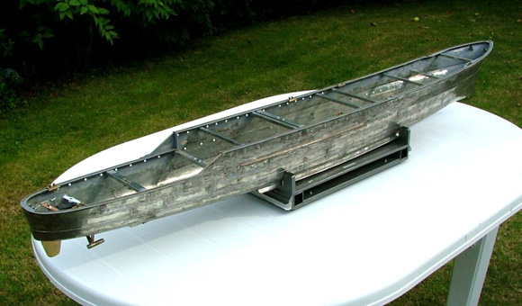
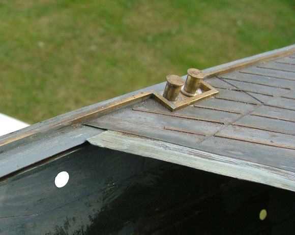
Enjoy more Model Boats Magazine reading in the monthly magazine. Click here to subscribe & save. In most cases the materials and techniques used are not seen as greatly important provided that the end product looks right. This is fair enough, and it would often be impractical to use the material that the prototype was built of anyway. All the same, for me there is a particular attraction to models that are made of the same materials as the originals, and perhaps are even built in the same way. In some fields this is normal. Model steam traction engines and locomotives, for example, are always effectively a small version of the subject, identical in both materials and construction. Some of the larger scale models of First World War aircraft are also effectively reduced size versions of the “real thing”, built with the wood, wires and fabric of the originals. This kind of “constructional realism” is less common in model ships and boats, but it is sometimes seen. The hull, deck and superstructure of Roy Skeats’ beautiful Fairmile are a good example of true scale materials and construction (which some of us were sorry had to be painted). Many models of Victorian steam launches not only use full size practice in their construction but are steam powered as well, and most of the early museum ship models are also small copies of full size, though they were often built specifically as “three dimensional drawings” to show the method of construction. True, the woods used might be different, but grain and texture don’t scale. Almost all of the marine models built of the “right” materials are of wood, or sometimes wood with resin/glass hulls, and steel models of steel ships are something of a rarity. Probably most of us who have used steel for model building first encountered it in a series of articles called “All Steel Construction”, which was incorporated into another series, “British Warship Detail”. These were published in “Model Maker”, the forerunner of “Model Boats”, between March 1958 and June 1964 and were written by the late Norman Ough, a considerable authority on warship construction, the master of model building in steel and a first class model shipbuilder in other materials as well. If you have the chance to see them, his models of HMS Lion, HMS Iron Duke and HMS Vindictive are displayed in the First World War gallery of the Imperial War Museum. These aren’t steel models but they illustrate the very high standard of his work. His model of HMS Dorsetshire in drydock is also owned by the IWM but is currently in store. Though it has an appeal as the material of full size ships, the main reason for advocating steel construction is that it has a number of practical advantages for the modeller. Its strength allows thin sections to be used, without the slightly heavy look which is often difficult to avoid when using wood or polystyrene sheet in the smaller scales. It doesn’t produce heavy hulls as scale, or near scale, thickness can be used. The hull shown in Photo 1, for example, is 145cm long and weighs less than 2kg complete with bracing, motor mounts and shaft glands. Steel can be shaped easily and it is very forgiving. If you get a job wrong then it can be unsoldered for another go. Try that with solvent welded polystyrene or resin bonded wood. Disadvantages? Well, it’s really best suited to riveted hulls with lapped plates, though it could be used to reproduce a welded hull if the butted plates were internally strapped. It does need a few new techniques, especially if you’re not used to soldering, but they aren’t difficult to acquire. The usual building method needs a hull former to be made, increasing the work, but in this it is similar to glass fibre hull moulding which needs a mould to be made as well. Rust? Not a problem, mainly because the steel used is tin plated (which also makes it easy to solder) and any areas where the plating has been damaged will be protected by an etch primer anyway, though it might be thought better not to put a steel boat in salt water. That said, a primed and painted steel hull should be perfectly safe (and much safer than aluminium). Brass is seen used as a model building material more often than steel but it is much heavier and less robust so that, in the smaller scales, thinner steel can usually be used. It is also more expensive. There are some parts that are better in brass, however. The wraparound stemplate in Photo 2 has a compound curvature in opposite directions which is difficult in steel, and even the brass needed annealing a couple of times in the forming. In spite of the comments made earlier steel models depart from full size methods of hull construction in two major respects. First, the plate laps are soldered and not riveted. Rivets could probably be represented by making up a small press tool to emboss the edges of the plates, which might well be worthwhile in the larger scales. This is largely a matter of judgement as rivets can be obtrusive on small scale models. The other departure from full size practice is in building the hull over a former, the usual method for tinplate hulls, rather than on frames. A framed hull would be more complicated to make, and certainly heavier. At the Sinsheim model show in 2005 I saw beautifully built sheet metal hulls with frames, Photos 3 & 4. They are in brass, but the principle is the same. In this case, the method of construction still used a former, not solid but made up of a series of separate hull sections with gaps between them to accommodate the frames. This former can just be seen in the upper left background of Photo 3. Norman Ough made a steel tramp steamer with frames, though this also was built on a former and had the frames added later. There are some modelmakers using steel but it is, I believe, greatly undervalued and I hope that you might be persuaded to take a more serious look at it as a building material, if not for hulls then at least for some of the larger components. Construction TechniquesThe articles by Norman Ough are difficult to improve on and photocopies of them can still be obtained from “Model Boats”. Further information is given in chapter 3 of “Scale Model Warships”, in which Col. H.T.N. Batchelor described the methods used for his tinplate model of HMS Pheasant, a Modified Black Swan class sloop. This is an excellent and well illustrated account which I found very helpful, and the explanation of hull drawings, with the descriptions of marking out the hull former and of steel hull construction are particularly well done. Chapter 4 of the same book, by Giancarlo Barbieri, describes metal superstructure construction. Regrettably the book is now long out of print but it is well worth seeking out. It is invaluable, particularly for warship modellers.
|
|
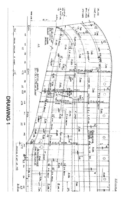
I can scarcely hope to improve on these expert descriptions of the methods used and my object in writing this is to supplement them by covering tools and materials which have become available since they were written, and any different techniques which have become practicable as a result (or, at least, those which I’ve found helpful). I shall certainly not attempt to rewrite Norman Ough, and there is no need to try since copies of his articles can easily be obtained. Most of them deal with specific aspects of warship design and construction, rather than with building in steel, making them a valuable source of information so there will be a list of them at the end of this article. The published material on steel construction (including, I’m afraid, this article) relates mainly to warships but, obviously, the methods are equally applicable to any riveted steel ship. Norman Ough’s descriptions of steel building techniques are mainly in “All Steel Construction” (referred to in future as ASC), are available direct from the Editor – see details later. Unfortunately there is not the same ready access to Col. Batchelor’s excellent work so I will try to cover any aspect of it which might be helpful and which is not available from Norman Ough. Since I’ll be referring to the author fairly frequently I’ll sometimes use his initials, NAO. Similarly Col. Batchelor will be HTB. NAO’s articles are illustrated by some of his own drawings. He produced a range of warship, warship fittings and armament drawings which are still available and his ship drawings are listed at the end of this article. Many of these warship drawings were based directly on the copies of the “as fitted” drawings then held by the Admiralty at Bath. “As fitteds” are probably the best basis for warship model drawings. One set of them was normally on the ship, a second set was held by the Admiralty, as the MOD (Navy) was in the period when warships were riveted, while a third set was in the shipbuilder’s records. This multiplies the chances of tracking them down but they are builders’ drawings and have some limitations for the modelmaker. For example, they don’t show detail of armament, boats and other large fittings supplied to the ship constructor by specialist manufacturers. Instead they usually show a block outline of the item with a brief but precise description such as “QF 4” Twin HA/LA Mk XV on XIX mounting” though this is, at least, specific enough to guide you to a detailed drawing of the fitting. Also, as their name indicates, their purpose is to show the ship at the time of construction without subsequent modifications and additions. In practice they don’t always do this completely, as later detail changes during construction aren’t always recorded on the drawings. Also, variations between ships of the same class are common and the differences sometimes don’t appear on the “as fitteds”. Drawings of a ship at a later period of its life, or after a refit, must therefore draw on other sources of information as well. Norman Ough’s ship drawings include much of the detail missing from “as fitteds”, which he based on other sources of information or, where these weren’t available, on his own extensive knowledge. For example, they always include hull plating but, as noted below, shell plating information was (and is) hard to come by. Therefore the plating details might sometimes have been based on NAO’s knowledge of constructional practice, rather than on drawings of the particular ship. Where this is the case it is likely that more specific information was not available, and is probably still not available. In the case of armament, however, there is now much greater access to drawings, photographs and museum examples than in those days and modern drawings may therefore be more accurate and precise. This applies particularly to the small scale drawings which were included as additional detail at the bottom of some of the ship drawings. Ironically, the great improvement in available information which often makes modern drawings more reliable is partly due to Norman Ough who worked hard to have drawings and manuals, then still considered confidential, made available for reference rather than destroyed. Hull ConstructionThe first requirement is a former over which to build the steel shell. This can be produced by any of the standard wooden hull techniques, bread and butter, plank on frame or even carved from solid. However, it does need to be of wood as it has to be fairly heat resistant, the surface must accept marking out and the plates will need to be temporarily pinned in position. If plank on frame is chosen the planking should be reasonably thick to be robust enough to be used in helping to shape curved plates. Ideally the hull former should be slightly undersize to allow for the plating thickness, which will average 0.020in (0.5mm) at the overlaps. Fortunately “tumblehome”, which results in a lower part of the hull being wider than the deck, is relatively rare in more modern steel hulls though it might be encountered in early warships or at the stern of more recent designs. Armour belt “bulges” on capital ships present similar problems. If this is a factor then some arrangements will need to be made to allow the completed shell to be removed, perhaps by making the former in sections to allow it to be dismantled. Shell PlatingObviously you can’t make a model of anything until you know what shape it is and how big it is and this, of course, applies equally to the shell plating. The second part of ASC describes marking out the plating but does not say what to base the marking out on, though HTB does. Ideally you need a “shell expansion” drawing, which will show the positioning and unit weight of each plate, details of the joins and the position and size of all hull openings. Plate thickness can be derived from the unit weight, usually given in lbs/square foot (since riveted hulls predate metrication) as shown in Table 1. If you haven’t come across one before a shell expansion looks a little strange, and part of one is shown in Drawing 1. It shows the plating of one side of the hull as if it had been peeled off in one piece and laid out flat and looks no more like a hull than a tigerskin rug looks like a tiger. It contains only one potential trap for the unwary, just as a map projection of the world distorts the continental shapes, so a shell plating drawing distorts the shapes of the plates, though mainly transversely along the station lines. This, however, isn’t a serious problem as it will be corrected when the plating layout is transferred to the hull former and the plates will be cut to comply with the shapes drawn on the former. A more serious problem with shell expansion drawings is their rarity. The “as fitted” drawings don’t normally include the shell expansion, the only copy of which is likely to be with the shipbuilder or, nowadays, whoever has the shipbuilder’s drawings. This could be one of the museums or, possibly, a university (drawing sources is a topic in its own right). All in all, a bit like hen’s teeth though, unlike “as fitteds”, the shell expansion should be the same for every ship in the class, which improves the chances of finding one a little. If a shell expansion isn’t available all is not lost. The best alternatives are: An expansion for a similar ship. Photographs, including drydock photographs (if available) and study of any expansion drawings available, of any ship. Drawings showing plating runs by an expert, who might well have estimated the plating pattern on a “best guess” basis but will have done so from a sound knowledge. Even with the shell expansion it’s helpful to have some idea of plating practice, but if you don’t have this drawing, and have to base the plating on other information or on what it was probably like, then it will be essential. Representing plating by adding lithoplate, paper or polystyrene plates to a hull is now a fairly common model making technique so that the principles of plating practice are probably reasonably well known, and they are covered in ASC, part 1, and by HTB, who also describes transferring the plating layout to the former in some detail. However, they are a basic essential for steel construction so are worth describing anyway (you can always skip this bit). Riveted ships were built in runs of plating running fore and aft called strakes and the vertical joins between the plates could be lapped or butted, Drawing 2. If butted they have a butt strap, a strip of plate covering the joint to which the ends of the plates were riveted, which might be internal or external. The plates constituting the sheer strake (the top edge of the hull) are often butted, with external straps. Internal strapping gives a smoother finish and might have been used along a waterline or, for example, in a private yacht and NAO notes that internally strapped butting was the usual practice for all plating in destroyer designs prior to the “Tribal” class. The smoother finish would have improved speed by reducing drag, much like flush riveting in aircraft. There is a story, which might even be true, of Supermarine investigating the benefits of flush riveting by gluing half a split pea on each of the flush rivets in a test aircraft to simulate round rivet heads. There are many runs of internally strapped butts in my model of HMS Brissenden, but this was a Thornycroft design and not necessarily typical of contemporary Admiralty practice. Internally strapped butting was more costly and would have been used less in small ships built to a price. The laps in lapped plating runs normally trail, as fish scales do, but this is not invariably the case and the occasional plate might be found to be lapped in the opposite direction, usually at the stern. However, if in doubt use a trailing lap. Horizontal joints between runs of plating are lapped, but not upper over lower as in clinker planking. The strakes are arranged as alternate “in” and “out” runs so that both edges of an “out” strake overlap and both edges of an “in” strake are overlapped. This is shown in ASC 1, and in Drawing 3, which is a detail from a shell expansion and includes an “out” strake (A) and an “in” strake (B). Again, this is usual but not invariable and a strake on a curve might sometimes be found with a “clinker built” arrangement, “in” at the top and “out” at the bottom, an example of which (strake E) is also in Drawing 3, together with an example of the reverse, a strake (C) which is ”out” at the top and “in” at the bottom, though this is something of a special case since it is associated with a “stealer” plate. “Stealer” plates are found in a slightly more complex join, used where two strakes, which become narrower approaching the end of the hull, eventually become one. Drawing 3 shows that strakes C and D are united by the stealer plate F and also that strakes C, D and F together form an “out” strake. The sheer strake is invariably “out”. Vertical lapped joins may be simple laps or may be “joggled” as shown in Drawing 2 but it might well be preferable not to reproduce this except when working in a fairly large scale as, like rivet detail, it could become obtrusive. Marking out the FormerThe next stage is to mark the plating on the surface of the former, together with hull openings (condenser inlets and outlets, asdic stowage, hawseholes, portholes, magazine flood inlets etc.). It is relatively straightforward and is covered in ASC parts 1 and 2, but a little additional detail might be helpful. The former may be marked straight onto the wood, or first given a coat of white primer to make the markings clearer. If this is done then it must be a very light coat to avoid the risk of “baking” the plates onto it during soldering. First mark the line of the keel centreline, which will probably be the only line on the hull which is straight in both planes, with the positions of the stations and of any frames which are close to fittings needing to be marked, such as A frames. The station and frame lines can now be put on, perpendicular to the keel. A strip of thin card is now placed on the expansion, along a station line with one end on the keel centreline, and the edges of the strakes marked on it. The card strip can now be laid along the station line on the former and the strake edge markings transferred, with the process repeated on the other side of the hull. When all of the frames have been treated in this way it becomes a simple matter to join the dots to provide the strake edge positions. The vertical joins between plates are more easily transferred by measuring them from the nearest station or frame. However, note that the ends of the plates are often square so that the joins might or might not be parallel to the frames at either end of the hull where the strake lines follow the hull sheer. Hull openings and the positions of fittings are marked in relative to station and strake lines, in the same way. You are likely to see from the expansion that the hull plating isn’t completely symmetrical since hull openings don’t necessarily appear on both sides, or in the same position on both sides. Building the ShellMaterialLarge tins and cans, once readily available free from the corner shop, have been supplanted by other materials. Baked bean cans are still with us, it’s true, but these are probably the least useful source since they have to be straightened and have the printing removed and will, even then, yield only small pieces of material. My model of HMS Kashmir was made of reclaimed tinplate, taken mainly from large, flat sided tins, but this involved a lot of preparation. As NAO says, new tinplate is much easier to work with. It’s no more readily available in small quantities now than it was then, but some sources are given at the end of this article. Shaping TinplateThe usual sheet metal working tools should be to hand, including a piercing saw with a metal cutting blade, a slitting saw and a selection of small files, and there are one or two special tools which will be needed, mainly home made or improvised, which will be described as we go along. I have had little success with the use of a hammer and punch as recommended in ASC part 1 since it is too easy to produce dents rather than curves, and use a variation of “rubbing” sheet into shape (also ASC, part 1) using a tool which might have been designed for the purpose, a teaspoon. The handle is held in the palm with the forefinger or thumb in the bowl to apply pressure when rubbing the tinplate, Photo 5. A stainless steel spoon is preferable to a plated one and a smaller version of the same tool can be made by straightening a pair of sugar tongs (try a car boot sale). If the tinplate is rubbed on a hard, smooth surface, dents or buckles can be removed or edge burring flattened. I use a piece of case hardened steel but NAO’s suggested flatiron sole would be ideal – if you can find an iron nowadays without an aluminium soleplate, full of holes. Placed on a piece of softwood the tinplate can be curved or even “dished” in a compound curve. It takes a little time but, by using the softwood and steel alternately to stretch the edges of the sheet, it’s possible to produce the compound curves in different directions as encountered in the flare of a bow, Photo 6. This photograph shows the large knuckle in the bow plating of Brissenden which helped to earn her reputation as a “dry” ship, and the ease with which plates can be made to fit changing hull curves can also be seen in Photo 7. Final shaping of each plate can be done on the part of the hull former that it has to fit. Illustrations are provided in parts 1 and 2 of ASC, and by HTB, who suggests using Fluxite as a lubricant, though I find that this can make the forming tool, i.e. the spoon, more difficult to control unless it is used very sparingly. Sharp bends can be produced if the material is first scored and a tool ground from a hacksaw blade is shown in ASC part 1 but a scoring blade is now available for craft knives, Photo 8, which can easily be touched on a grindstone to “freshen it up” from time to time. NAO suggests that hull construction can be commenced with the keelplate and worked outwards from it, or with the sheer strake, working towards the keel from either side. HTB favours starting with the keel and I have found this to be the better method, starting with the complete run of plates forming the keel and then adding runs of plating on each side in turn. In this way, only one side and one end of each plate will be soldered at a time. An attempt to solder two previously soldered areas of plating, or to replace a plate in a completed hull, can be disastrous. It’s not impossible, but it is very difficult since a plate, expanded when being soldered, is locked into position when the solder sets, before the plate has cooled, and buckling is almost inevitable. When only one edge is being soldered the plate is free to move. Even so, it is best to solder along the seam working towards the free end of the plate and avoid going back over the work. After shaping each plate apply flux along the two edges to be soldered and hold the plate in position on the former with drawing pins. Solder the short seam first, running a blob of solder along it slowly enough for the solder to be drawn in under the edge of the plate by capillary action (it should easily fill the entire width of the overlap) and following the soldering iron with the tip of a short wooden stick to hold the edge of the plate down as it cools, When the joint is cool solder the longitudinal seam in the same way, starting at the end already attached. The small fillet of solder can then be taken off with a chisel. NAO suggests an overlap of 1/16in, HTB suggests 1/8in. Unless the plate is to be joggled, in which case the overlap will show and will need to be near scale, I believe that 1/8in is safer, stronger and easier (or 3mm would do). In fact, where additional strength is needed even more could be allowed.
|
|
When adding a strake made up of internally strapped, butted plates the idea of using a continuous strip of several plates, possibly with the joins indicated by scribed lines, might seem attractive. However the expansion of a long strip can produce a cumulative distortion and cause problems, particularly if the plates are flat. It’s safer to add a strip of only two, or at most three, plates in this way, with a real internally strapped butt to the next set of plates. Of course, plate distortion is less marked as thickness increases and/or if the plate has a transverse curve, either of which provides a stiffer plate. A destroyer hull is usually built of plating ranging from 7 to 15 lbs/sq. ft. i.e. from about 5 to 9 mm. thick. In 1:48. scale this would give a thicknesses between about 0.1 and 0.19mm but it is difficult to use material thinner than about 0.15mm. Describing using 0.005in (0.125mm) material Norman Ough wrote: “Buckling of the plates was troublesome during the building of the author’s model of a “three island” tramp steamer……..as it was built of 0.005in. plating. This made the hull so thin that flat frames, as many as those of angle bar in the real ship, had to be added to stiffen it.“ and “There was really no need, as was realised afterwards, to have built her of such thin metal as the next gauge thicker would have been easier to work; it would have made a better hull and the bolder relief of the strakes would have been more realistic and not at all too emphatic when the paint was on. It is probably a mistake to be too much enslaved by absolute scale in a small working model: what is more required is a certain restrained boldness of treatment – what an artist would call “accent”.” For hull construction I use 8, 10 and 12 thou. (ok, 0.2, 0.25 and 0.3mm). 0.2 mm is adequate for the curved plates around the bilge, but thicker material is more rigid and easier to use for flat plates on the hull sides. Hull openings and portholes are more easily put in each plate before assembly. Drilling can easily distort thin sheet and holes are best made undersize and reamed out. Since most of the ports will be of the same diameter a small reamer is a worthwhile investment if not already available, while other sizes and shapes of hull opening will be deburred and trued up during the shaping operation. Propeller shaft and rudder fittings are much easier (and less risky) to install as you come to them rather than after the hull is built. Small hull fittings, such as escape hatches and the half round reinforcement of hawseholes are also much easier to deal with at this stage. Bilge keels should now be added as a part of the shell construction while the shell is still on the former, subject to the same precautions as when adding bulkheads, described below. Many small ships had a solid stemplate and it is better to fit this in a slot in the bow of the former to allow the plates to be soldered to it in sequence, rather than risk fitting a stemplate later. Larger and/or more recent ships will often have a “soft” bow with a wraparound stemplate, with or without a casting at the lower end where it meets the keel forming the forefoot. These are more easily fitted but might be more difficult to shape. Like any plate with a difficult shape a wraparound stemplate is more easily shaped from brass, which allows easy annealing if required and is therefore much more malleable. FluxesThough I have used it in the past, less aggressive fluxes than NAO’s suggested Baker’s Fluid are now available. The most corrosive flux which I use is a fairly mild version of a standard “Fluxite” type paste which cleans easily with most solvents. Low corrosion liquid fluxes are available, based on fruit acids (try a model railway supplier). Alternatively, in difficult situations, solder paint may be used as a flux, with or without additional solder, and it can also be used with a small gas torch for some work. However the work will need subsequent washing. SolderingI no longer use tinman’s 60/40 solder. The “received wisdom” used to advise avoiding cored solders due to the difficulty in removing resin residues but modern “no residue” types, made for the electronics industry, are very good and I use them almost exclusively, though with a paste flux. They are available in diameters down to 1mm. Lower melting point solders, available for a range of temperatures, are sometimes useful when adding to a subassembly joined with standard solder but are not often needed. If you don’t already have one it might be advisable to lay in a stock of cored solder as legislation banning the industrial use of lead in solders will take effect shortly and this is likely to affect their general availability. I understand that the replacement formulations, which use silver, will be more expensive and, more seriously, will not wet or flow as well as lead/tin. Since small scale model soldering often takes advantage of the flow characteristics of the solder to produce fillets, virtually using it as a structural material, this could become a problem. Almost more important than the solder is the iron. Kashmir was built with a 40 Watt iron and a good deal of difficulty. Subsequently smaller irons became available but, while they are suitable for work on small assemblies, they lose heat quickly when used on larger work, such as adding plates to a hull. The real advance came with temperature controlled irons. Though relatively expensive they transform model soldering. They are small, light and easy to use and the tips can be changed quickly and easily. Moreover they respond immediately to compensate for the tip being cooled by larger work, reproducing the heat reservoir characteristics of a much bigger iron, and the tip temperature can quickly be reset to suit the tip, work or solder. A temperature controlled iron is almost an essential for fine work. For me, the invention of the temperature controlled soldering iron is right up there with that of the wheel and the Archimedean screw. Do not be caught without one. A small chisel is useful for removing surplus solder or, in restricted spaces, the sort of small tools shown in Photo 8 can be even better. These are ground from broken needle files, which seem to become available from time to time. An alternative method of removing solder, which was not available to NAO or HTB, is solder wick. This is a copper braid, available in a range of sizes from electronic component suppliers, which will remove solder cleanly and easily, with no risk of damaging the surface. The braid is placed in contact with the solder to be removed and then heated with the tip of the iron. As it melts, the solder is drawn up into the braid by capillary action. A run of solder along a joint can be produced either by drawing the tip of the iron along the joint or by placing the tip, loaded with a blob of solder, at one end of a prefluxed joint and allowing the solder to run along the line of the joint by capillary action. Either method will leave you with a blob of solder still on the iron tip which, if the iron is simply lifted off, will remain at the end of the joint. It can then be removed with the solder wick as described above, but this will also pull some of the solder out of the joint. However, if the iron is drawn away from the joint, still in contact with the work, it will take the solder blob with it to a convenient point where it can easily be soaked up without affecting the joint. Similarly, excess solder can be pulled out of a joint using solder wick. There will normally be a small fillet of solder left along a joint, which can be an advantage if you are reproducing a casting or a rolled steel beam (as in a quadrantal davit), and the size of the fillet can be varied by the amount of solder fed into the joint. However, a clean, sharp join might sometimes be required and, if so, the chisel will be needed. Use the chisel to cut the solder, rather than as a scraper, and keep it at a low angle relative to the work so that it runs over it instead if digging in and damaging the surface. A glass fibre pen will remove thin films of surplus solder or clean the work, though it can also strip the tin plating if not used cautiously. RigidityThe completed steel shell will need some bracing to become a usable, rigid hull. When removed from the former it will have longitudinal stability and won’t bend, mainly due to its U girder section, though the longitudinal plate laps which constitute fore and aft stiffening ribs also help. However, the sides will be flexible and the entire shell might twist fairly readily. These faults are easily corrected by the addition of a stiff inwale running around the edge of the deck, some cross beams at deck level and, if necessary, two or three bulkheads. Before this can be done the hull will need to be set up to be as true as when it was on the former. This might be easy or difficult, depending on the hull in question. Kashmir has a traditional destroyer hull with the forecastle ending about one third of the ship’s length from the bow. The rest of the hull is relatively shallow, with a round bilge. This design is very prone to twist, in much the same way as a steel tape measure in which the transverse curve gives it longitudinal rigidity but is too shallow to form an effective girder section. This hull was very difficult to support to a true shape to allow the inwales and transverse bracing to be fitted. In complete contrast, the hull of Brissenden was very stable and held its shape well, remaining almost the same as when on the former and requiring very little setting up. Brissenden has the forecastle break well aft and the bilge is much more square, a shape closer to that of a typical merchant ship hull, and this forms a deep girder section over most of its length. This was an intentional design characteristic of the ship, providing an increased structural rigidity which allowed Thornycroft to use lower grade steel than was necessary for conventional destroyer hulls of the period. It is interesting that this was one of a number of design advances of the Hunt Type 4 which was adopted for subsequent designs, and became virtually standard in small warships. The change also allowed personnel to move from one end of the ship to the other under cover, which was impossible in conventional designs in which the engine and boiler rooms took up the entire enclosed space amidships. The squarer hull section also reduced the traditional destroyer tendency to roll and to heel sharply on turns (which the model of Kashmir certainly does). Brissenden also had particularly large bilge keels and it is interesting that her sister ship, HMS Brecon, was fitted with stabilisers. This was very unusual for a small warship of the period, but the departure was not entirely successful as the heavy and fluctuating electrical load when the stabilisers were in use affected the stability of the ship’s power supply, causing problems with the radar. The stabilisers also occupied space which, in Brissenden, was used for fuel bunkers, increasing her range. Brissenden’s hull has not needed any bulkheads, as Photo 1 shows, and some of the transverse struts at deck level are there only to provide mountings for fittings and are not needed as bracing. Structural stability is provided mainly by a strong and rigid inwale, about 3mm thick and 10mm. wide, which also provides good support for the deck edge and a firm mounting for the handrail stanchions. It can be seen in Photo 9 and Drawing 6. The lower shelf is fitted first. It is cut in sections about 300mm long, taking the shape from the drawing of the deck edge, though this will need to be adjusted slightly where the angle between the deck and the hull side becomes acute, making the curve shallower. It is soldered inside the hull using a template which is long enough to span the widest beam and is shown in Drawing 4, to set the distance from the top edge of the sheer strake and the angle to it. The slot holds the shelf in position for soldering. The upper strip is fitted in the same way, this time cut to the true shape of the deck edge, using another template which is similar but which sets the angle of the deck camber as well, Drawing 5. A deck camber template is shown in Photo 10. This particular example is double thickness to provide for a small, spring loaded, aluminium clip which holds the plate in position for soldering. At intervals of about 50mm small separators are spot soldered between the strips. The solder fillet between the upper strip and the deck edge will run in easily from the outside of the joint provided that the two components are clean and prefluxed. Joins in the lower strips may be lapped, but those in the upper strip should be butted, with a small butt strap on the underside. After the gap between the two strips has been thoroughly cleaned the hull can be laid on its side and resin poured into the space between the strips. Theoretically, any resin would do but something fairly strong is preferable. I used epoxy casting resin on Kashmir and this is very strong but takes several hours to set. A better compromise is polyester or polyurethane, both of which are fast setting and adequately strong. A disadvantage of polyester is that the surface exposed to the air remains tacky, though it is possible to take advantage of the high viscosity of the resin to overfill the space so that the meniscus is outside it and the surplus can be filed off to give a neat finish, Drawing 6. Obviously it is possible to fill only a short section at a time, working around the hull and supporting it as necessary. The drawings illustrating the inwale aren’t to scale and proportions are only approximate. On completion the hull will be much more stable and transverse braces can be fitted at deck level or, more precisely, just under the inwale. For these a 6mm square U beam folded from 0.25mm tinplate is both rigid and light. Bulkheads can now also be fitted but this must be done carefully to avoid heating the hull plates sufficiently to soften a seam. If this happens then the seam will reset with the plate heated and expanded. Since it will no longer be possible to return the hull to the former the resulting bulge will be at least a problem, and might be disastrous. As previously noted, it is possible to eliminate this kind of distortion in a completed shell, but it is difficult at best and carries a risk of making matters worse. The safest method of fitting a bulkhead is to spot solder the edge in the centre of a plate, away from the seam, leaving the iron in place only long enough to make the blob of solder flow. This, repeated on each plate, will tack the bulkhead firmly into position. Working quickly and carefully it is now possible to fill in the gaps between the solder tacks with more tacks, a blob at a time working at separated points and not trying to get a continuous solder line. It is then possible to run each blob carefully into the next. Alternatively, once the bulkhead has been tacked firmly in place the edge can be bonded to the hull with a fillet of epoxy resin and this is probably the safer approach. When soldering onto small assemblies which have already been soldered it is usually possible to minimise the heating effect by getting the iron “in quick and out quicker” and, if necessary, clipping a piece of wet cotton wool to the part that needs protection, as a heatsink. The small aluminium clips shown in Photo 11 are invaluable for this, and for holding parts in place while soldering. The upper three are as supplied, while the lower ones illustrate how easily they can be modified to suit particular requirements. They are used in ladies’ hairdressing and are stocked by some chemists and drugstores (Superdrug have them in stainless steel). However, the use of a heatsink isn’t practicable when dealing with large sections that need more heat input to make the solder flow. The SpurnwaterOn warships with guardrails the spurnwater is a strip of wood around the deck edge, usually just inside the stanchions. It is normally virtually continuous except for a gap at the stern and this can be turned to advantage in a model. In a working model it is, of course, essential to have some access to the inside of the hull and it is often difficult to decide on separation points for sections of the superstructure, particularly if guys and stays must be allowed for. By using the spurnwater as a separation point the entire deck may be made removable, complete with all standing rigging, and with an easily concealed join. This can be seen in Photo 9 and in Drawing 6. There may still be some items bridging the spurnwater, for example the sponson supports shown in Photo 12, but these are usually fairly easy to provide for. The Deck and SuperstructureThe deck is constructed on a former in the same way as the hull and the plating is similar except that the longitudinal edge of each run of plating will usually be lapped over the next running down the camber towards the deck edge. Thus only the central run is an “out” lap on both edges. The ends of the plates are usually lapped, with the forward plate over the after plate like hull plates, and may be joggled. The ends of the plates along the deck edge are likely to be butted, with internal straps, to give a smooth surface. In representing areas where Semtex or Corticene has been laid the best method is probably to butt all joins, with internal straps, though plate sizes don’t have to be to scale and can be as large as can be shaped satisfactorily. Like butted strake plates, there is a temptation to make these smooth sections of deck from one piece of tinplate, and this is sometimes possible, but the combination of sheer and camber will usually produce a compound curve which makes it impracticable. Of course, if your ship has a planked deck then all of this detail becomes irrelevant and life might be easier. The deck former is best made plank on frame. If it is built up from a baseboard which is parallel to the waterline in both planes then this board can be used as a datum for the superstructure. One approach to constructing the deck and upperworks is to cut holes in the deck former which allow the main components of the superstructure to be made to stand on the baseboard, truly perpendicular, or with packing if required to be raked, so that the deck can be built up to them. This avoids problems in fitting units truly vertical on a deck which, due to camber and sheer, has no flat surfaces at all and in matching the bottoms of the units to the resulting compound curves. The technique of building over a wooden former can also be applied to some of the larger fabricated fittings, such as gunshields, and it is equally applicable to ships’ boats, which can be made with hard chine hulls, as in Photo 13, or clinker built with soldered brass strip “planks”, as in Photos 14 & 15. These hulls are subsequently fitted out internally in the same way as the ship hull. Some formers are shown in Photo 16. In “Scale Model Warships” HTB describes the use of wooden formers for building the main superstructure units. More details are given by Giancarlo Barbieri, together with a photo which shows some of the superstructure of Brian King’s HMS Dreadnought, which was used in his description to illustrate this method of construction. (Unfortunately we could not obtain permission from the publishers to reproduce this photograph. Ed.)
|
|
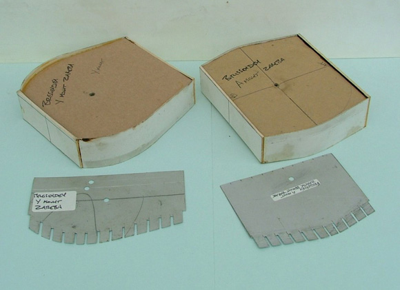
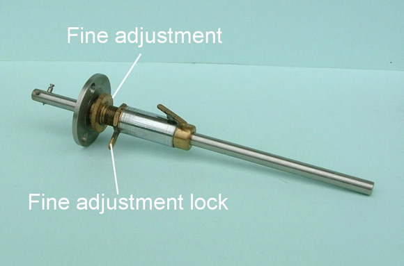
The formers described above all have hollow structures soldered over them in the same way as a hull, but a variation of the technique allows jigs to be made to set the position and angle of other items, sometimes difficult when it must allow for both camber and sheer. Since they are not soldered over, these jigs can be made of card or polystyrene and Photo 17 shows some examples of zareba jigs, together with the lithoplate jigs used for spacing the support brackets. BuoyancyOne major disadvantage of building a hull of steel (whether a full size ship or a model) is that, if flooded, it will have the buoyancy of a brick. Granted, no modelmaker expects this to happen to his or her Pride and Joy but, then again, neither did Harland & Wolff. One precaution is to maintain prototype practice (i.e., do what the big boys do) and fit bulkheads. As noted above, some might be needed anyway for structural reasons, but too many in a model can be a nuisance. Another approach is to put in some buoyant material, another full size practice (for boats anyway). The usual things seen in models range from table tennis balls to the squiggly pieces of polystyrene foam produced as transit packing, most of which have the disadvantage of being unsecured items rattling about in the hull. The forepeak of my Kashmir is filled with “in situ” foam, now available in aerosols, but I wouldn’t use this again as, like “cast in” ballast, it has the disadvantage of being too permanent and could become a problem if you ever need to work on the hull for any reason. My preferred method is to line the hull with strips cut from ceiling tiles, Photo 18. This puts a surprisingly large quantity of polystyrene foam into the hull, without it being obtrusive. It also provides a neat and tidy finish inside the model and has the incidental advantage of making it less resonant, which sometimes puzzles people who tap it to see if it’s really made of tin. A minor difficulty is that most of the adhesives which the foam will tolerate won’t stick to the hull and those which will, such as epoxy resin are, again, too permanent. An effective solution is to use double sided adhesive tape, which is easily applied and is secure but removable. Any spare space can be filled using the same ceiling tiles, installed in tightly fitting vertical slices without adhesives, also easily fitted and removed. Since neither glass fibre nor vac-formed hulls are intrinsically very buoyant the same technique might be useful for them also. Special Jigs and ToolsLike most modelmakers I have a few home-made gadgets. They are not always essential (or successful) but the better ones do help to make work easier and/or more accurate and some are described below. Tinplate can be scored and folded as previously described, but a small forming tool, while not essential, can be helpful in obtaining sharp, true right angle bends, Photo 19. Alternatively short folds can be made using a vice, though for longer folds it is useful to extend the effective width of the jaws and a tool to do this can be made up from a couple of pieces of 1in steel angle, Photo 20. When superstructure parts must be added, a datum truly perpendicular to the waterline is needed which the tool shown in Photo 21 provides. To use it the deck must be level but by then it may well have had stiffening ribs fitted under it to hold the camber and it will not be possible to return it to the former, though slots can be cut in the former to accommodate the ribs. Alternatively, the deck can be fitted in place on the hull and, if a proper building stand has been made it will ensure that the hull, and therefore the deck, is truly level. Another method of ensuring a level deck is to fit suitable supports under it and this will also prevent distortion of the deck when it is off the hull, Photo 22. Whichever is chosen a set square will provide true verticals only up to the deck edge. The tool allows the true vertical to be extended past the deck edge as far in as the centreline and, since the post is vertical in both planes so is the line of the extension. It also functions as a height gauge. The slides are made from a couple of cheap plastic calliper gauges. Porthole rigols (sometimes called “wriggles” or eyebrows) must be concentric with the porthole and the jig shown in Photo 23 ensures this. The rigol can be made from a ring of wire formed around a twist drill shank and the jig is fitted as shown in Drawing 9. In 1:64 scale round wire is acceptable but square wire could be used in a larger scale. The wire ring is placed over the jig, the upper half of it is soldered onto the hull and the solder bead is drawn away from it as described earlier. Finally the lower half of the ring is cut away. The same soldering technique can be used for deck tread strips, which are formed from flattened brass or copper wire, Photo 24. To ensure alignment it is easier to solder them on as a continuous strip and cut the gaps afterwards. Photo 25 shows a small scale version of a marking gauge, 160mm long, with the addition of a fine adjustment. The construction is clear from the photograph and the scribing point is ground from a tungsten carbide dental burr. A final tip. The fact that the model is made of steel can be turned to advantage. Brissenden’s deck is held on by Dzus fasteners but a stubborn deck edge at the stern refused to stay down. The solution is shown in Photo 26 which shows a small horseshoe magnet, but smaller and neater magnets are now available from Action Kit. Photo 27 shows them compared with one of the horseshoe magnets. They are very powerful for their size and had to be stuck down for the photograph to stop them flying together. PrimingMetal surfaces should be primed prior to painting and a primer intended for car body repairs can be used, though it is easy to apply too great a thickness. I prefer an etch primer, applied very thinly. Zinc chromate primer is excellent and was used on Kashmir, but that was a long time ago. It is now regarded as a hazardous material and I haven’t been able to obtain it recently. The best alternative is one of the etch primers produced for model use which are stocked by most model suppliers and a good etch primer should also deal with any areas of bare steel where the tin has been damaged. However, in industry steel is often “passivated” by creating a thin phosphate layer on the surface, and this is an alternative approach. This layer can be produced by “Jenolite”, a phosphoric acid based treatment available from most car body product suppliers. It comes as a liquid or a gel but I prefer the liquid. The instructions suggest that a thin layer should be painted on and, after 15 minutes, a second layer applied and then wiped off, which removes most of the material but leaves the metal passivated. The steel surface will be seen to have turned grey. The treatment is intended for steel and has relatively little effect on tin so may be used on areas of tin which have patches of exposed steel. It produces a very thin coating which doesn’t obscure fine detail, but if you do use Jenolite please note the handling precautions on the plastic bottle. Material SourcesIt is, unfortunately, difficult to buy tinplate in small quantities and my previous supplier is no longer in business but I know of three sources. The first is RS Components, who stock 500mm x 300mm sheets in several thicknesses. However, there are some snags. RS will supply trade customers only, so that you will need to have access to an account, the minimum supply quantity is 10 sheets and they don’t stock the most useful thickness of 0.25mm. If you have internet access their catalogue is available on www.rswww.com but details of the three thinnest sheets available are: 0.2mm stock no. 682-444 £15.95 (10 sheets). 0.3mm stock no. 682-450 £17.44 (10 sheets). 0.4mm Stock no. 682-466 £24.47 (10 sheets). A much better source is Afon Tinplate, Bryntwod, Swansea, SA5 7LN. I haven’t bought from this company (which normally deals in very large quantities) but the Sales Manager, Neil Jones, is extremely helpful. He is prepared to supply tinplate in the range of thicknesses needed for model making in single sheets at around £10 per sheet. The sheet size will depend on stock at the time but is, typically, 800mm x 800mm. Telephone 01792 313030 and ask for Neil Jones or Alison James. Mr. Jones tells me that the hardness which we require for easy working is Temper 2 to 3 or, in the European classification, 52 to 55, so mention that it is for ship modelling (and it might help also to mention this article). VAT and carriage will need to be added to the prices given above. The third source is Bellingham Tinplate, 34, Caswell Road, Newton, Swansea, SA3 4SD. I haven’t bought from this company either. It also normally deals in large quantities but Andrew Bellingham is very helpfully prepared to supply single sheets and, again, the sheet sizes will depend on current stock. Typically a sheet 860mm x 690mm x 0.25mm would be about £6, but carriage could be costly if arranged by the supplier. Telephone Andrew Bellingham on 01792 360716 and, again, mention that it is for model making. Action Kit is at 82, Kestrel Way, Sandy, Beds., SG19 2TS. 01767 681564 (www.actionkit.co.uk). “Scale Model Warships” can still be obtained second hand. It was edited by John Bowen and published by Conway Maritime Press in 1978. It’s ISBN number is 0 85177 170 X. Sources of DrawingsIt is often difficult to locate drawings, especially of some of the older ships, even when they are known to exist. Shipyards have closed and their records have been passed to museums or, sometimes, universities. Other collections, such as Norman Ough’s drawings, have changed hands, sometimes more than once. In some cases the availability of drawings is advertised, for example the Thornycroft collection, held by the National Maritime Museum, has been featured in Model Boats (in August 1994). Often a special interest club or group will know the whereabouts of drawings of ships in their field of interest. The Surface Warship Association, as an example, has a very useful archive of Warship Drawing Collections. It also seems likely that many individual modelmakers will have searched out the drawings of a particular ship and will know where they can be found and it would be a service to ship modellers if this information could be made available to us all. The editor will be pleased to collate and publish any details of drawing sources that are sent to him, whether from individuals or organisations so, if you have some information, please send it in by post, E-Mail, carrier pigeon – anything, but please send it. Articles in “Model Maker” by Norman Ough“British Warship Detail” & “All Steel Construction”. The first two items (ASC1 and ASC2) are obtainable direct from the Editor on receipt of an sae – please send to Model Boats ASC, PO Box 6016, Leighton Buzzard, LU7 3GS. There is no charge for these. For ALL other items listed below that appeared in Model Maker, these can only be obtained from Customer Services Photocopying. Contact them at [email protected] or 01689 899228. There will be a charge. All steel construction – 1 Dec.1958 – P608,609
|
|
Norman Ough’s drawings are now held, with the Macgregor collection, by the SS Great Britain Trust, Great Western Dock, Gas Ferry Road, Bristol, BS1 6TY. Tel: 0117 9260680. The trust also holds the drawing collections of E.N.Wilson and Edgar J. March. Available ship drawings by Norman Ough are: HMS Duke of York 1941-1958 1in. = 16ft. HMS Warspite, 1in. = 16ft. HMS Lion, 1in. = 16ft. HMS Hood HMS Amethyst HMS Hedingham Castle, 1in. = 8ft. HMS Dido, 1939, 1in. = 16ft. HMS Curacoa, 1916-1942, 1in. = 16ft. HMS Sheffield, 1in. = 16ft. HMS Penelope, 1936-1944, 1in. = 16ft. HMS Ajax Sheet 1 O/S/11A £8.50 HMS Dorsetshire Sheet ! O/S/12A £9.20 HMS Vega V Class 1916-1945, 1in. = 16ft. HMS Daring D Class 1934, 1in. = 16ft. HMS Matabele Tribal Class 1936, 1in. = 16ft. HMS Cadiz Battle Class, 1in. = 16ft. HMS Kashmir J/K Class, 1942, 1in. = 8ft. HMS Marvel Algerine Class, 1in. = 8ft. HM Submarine E29, 1in. = 8ft. HM Submarine L52, 1in. = 8ft. HM Submarine Olympus O Class, 1in. = 8ft. Picket Boat I understand that more detailed information on these drawings is included in a brochure that can be bought from the SS Great Britain Trust.
|
Model Shipbuilding in Steel
by
–
Advert
Enjoy more Model Boats Magazine reading every month. Click here to subscribe.
Article Tags:


