The Reverend PETER SPENCER describes his fine model of this schooner
Brief history
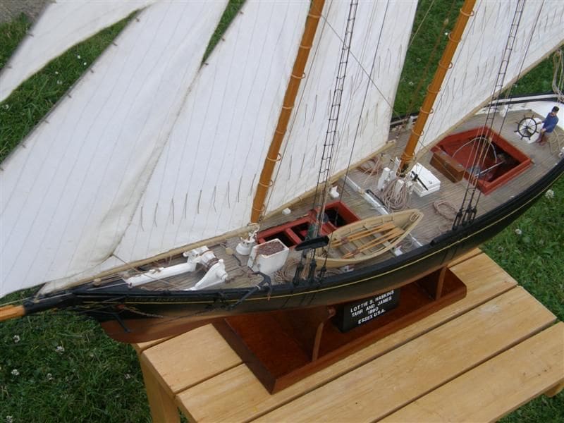
The schooner Lottie S. Haskins was built by Tarr and James at Essex, Massachusetts, USA in 1880 to the design of George M. MacClain. He held shares in her and also commanded her for some time. Lottie S. Haskins was renowned for her sailing qualities and it was said of her that she would tack under almost any conditions except a dead calm, but she was also a fast sailer. The length of her hull was 75 feet and a number of similar vessels are believed to have been built to her design.
Enjoy more Model Boats Magazine reading in the monthly magazine.
Click here to subscribe & save.
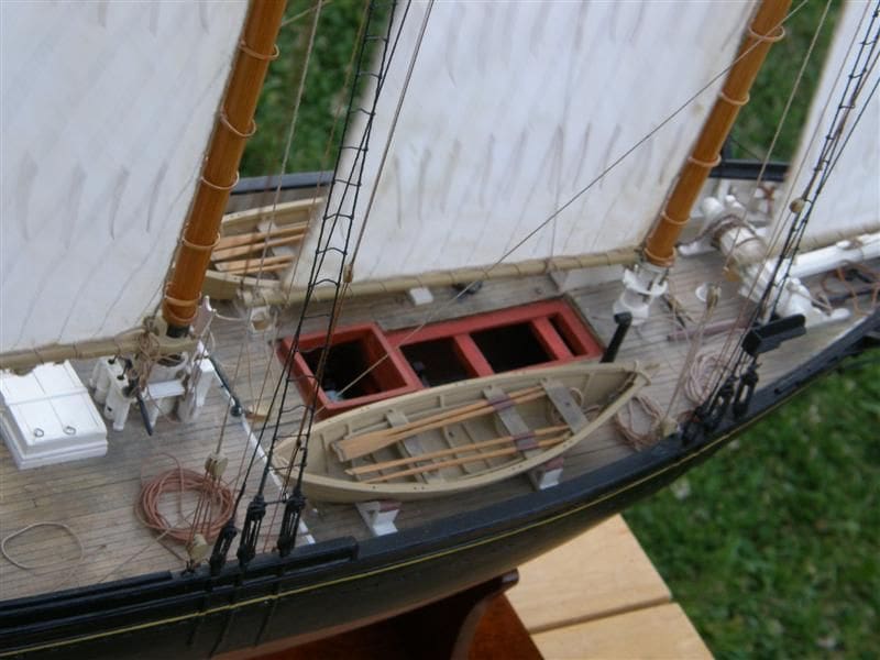
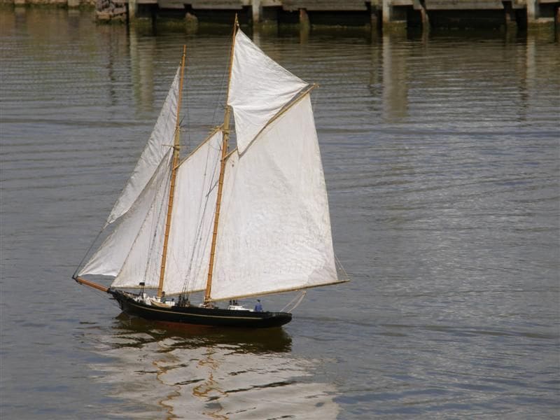
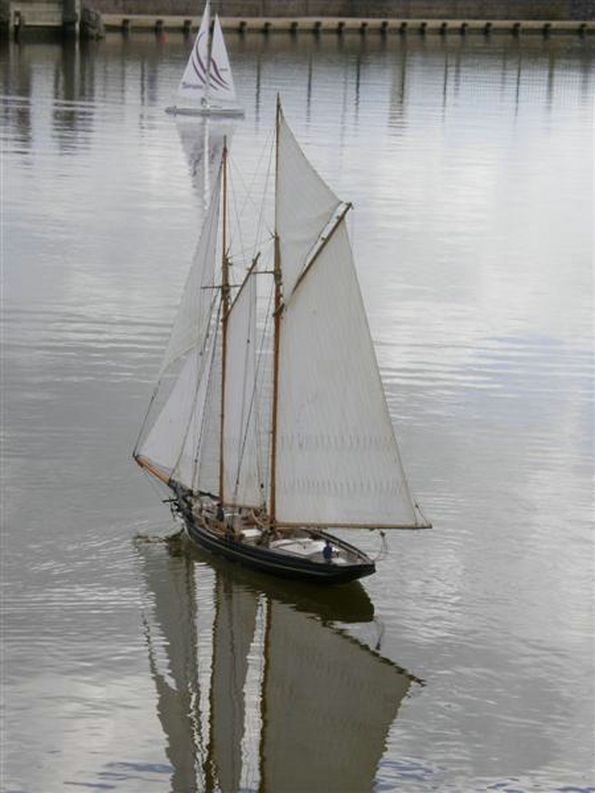
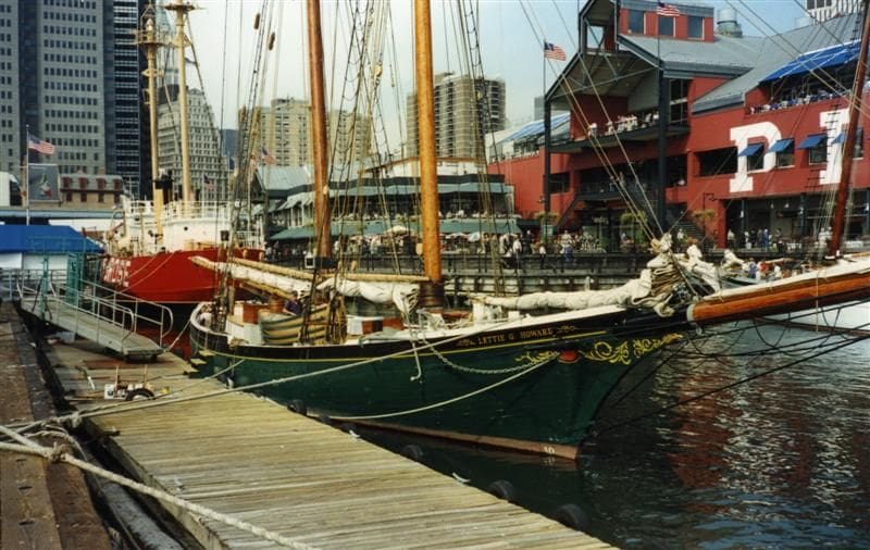
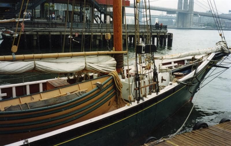
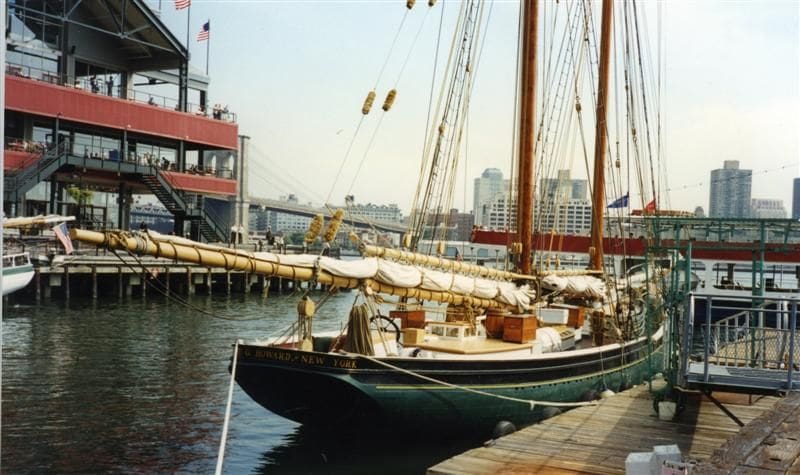
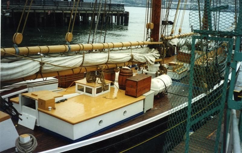
My model was built as a result of reading The American Fishing Schooners 1825-1935 by Howard I. Chapelle (1973), which is not only a huge source of information on these schooners in general, but has scale drawings on every aspect of them as well. Another reason for building the model, was that given the original ships sailing qualities, I thought it would be likely to sail without resorting to an outsize rudder or false keel, which indeed I found to be the case when it was finally completed. While building the model I was fortunate to come across the fishing schooner Lettie G. Howard, recently restored and very similar to the Lottie S. Haskins, perhaps being one of the ships built to her lines, Photos 1, 2, 3 and 4. Her present name is not her original one as is so often the case with vintage craft.
I didnt plan to write an article on building this model as that only came after encouragement from our Editor via Readers Models, so step by step building pictures are scarce, but I hope the following notes will encourage others.
The hull
I read somewhere that for a scale model to sail well it should be three feet long or more, so I enlarged the plans to a suitable scale of 3/8 inch to one foot with the aid of proportional dividers. I consider this to be essential, especially if the various drawings relevant to the ship are at different scales. Proportional dividers are very useful in this respect.
I made a drawing of the side of the ship, positioning the frames in accordance to the mould loft sections and I also made a drawing of those same mould loft sections. For everything else I took measurements directly from the book using the proportional dividers.
By way of materials, I used pine from the local DIY store. However, I had some oak of my own for the stem, keel and stem post and an old spruce dinghy mast for the masts and spars. So in other words the materials used were from local sources or were spare stock material.
The disadvantage of this sort of project is the time and labour spent cutting out the various bits and pieces by hand, the planks in particular. One of the most useful tools I have is a small seven inch plane which I use holding upside down and pulling whatever I am shaping towards me over it and much of the model was made using this technique.
The hull was built upside down on a building board beginning with gluing the stem, keel or stern post together with epoxy of the slow setting variety (Araldite) and then fixing them to the board using a strip of thin plywood on either side at each end.
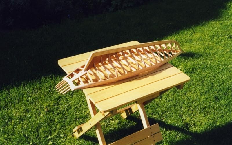
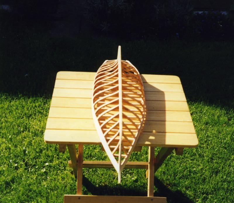
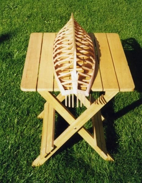
The frames were then made one by one and located in the same way. Because of the sheer, the centre frames would not have reached the building board so I extended these temporarily, to be cut to the proper size later. I then glued three planks on either side from the stem to the fashion timber of the stern and removed the model from the building board. The next task was to make the deck beams and glue them in place using epoxy, making sure that the camber on each frame was correct. Photos 5, 6 and 7 show the hull having been removed from the building board, with the attached planks from the stem to the fashion board and the deck beams and stem timbers also in place. These pictures were taken some years ago, so I can only apologise for their quality.
Planking notes
I built up the after part of the model, the stern timbers butting on to the fashion timber and planked the rest of the hull, thus in a relatively short time the hull was soon complete. Sounds easy in words, but planks have to shaped and that can be time consuming. However, if you aim to just add a plank or two each day, the task does not take too long and you can visually see progress after each work session.
It is important to remember that deck and hull planks should conform to the rules applied to full-sized ships and information on this may be found in Harold Underhills book Plank on Frame Models and Scale Masting and Rigging -Volume One (1968).
One of the conventions is that where two planks join on a frame, there must be at least three planks without a joint on either side and there are other rules concerning plank length. Planks often need to bend or twist as they go around a hull and are therefore steamed into shape and I usually do this by sticking them down the spout of a kettle. Remember though that boiling water hurts! Once pliable they should be retained in place with whatever works for you, be it pins, clamps, rubber bands, etc.
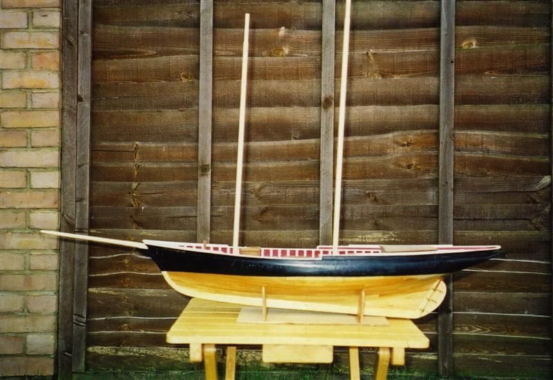
I began at deck level, gluing the planks on to a frame and to one another. The spacing for each plank was worked out easily using proportional dividers. I avoid using any dowels to hold them in place as they tend to show when planks swell. The first stage of construction of the masts and bowsprit was next completed and the rudder installed. This was built up as it would have been on the original ship, but with additions so that it could be radio controlled. Photo 8 shows the basic complete hull with initial work on the masts in progress.
Bulwarks
The port and starboard covering boards were made and glued in place, holes being made with a small chisel for the stanchions and then these were added. I cut scuppers into the lower planks. These, together with the other planks were glued to the frames up to the capping rail, having first been steamed to shape. The capping rail was made and glued in place with additions fore and aft, and finally the transom and other details were added.
Masts
The masts were carved from spruce, first planed square, then octagonal, then sanded round by hand except in the area of the trestle trees. The topmasts were constructed in the same way and made to be easily removable to ease getting the model in and out of a car, Photo 9. They were fitted with fids and then I made hoops from strips of veneer steamed round a piece of wood the same diameter as the mast. The ends were held together until they held their shape and once dry these were glued together. All other detail parts including those of the gaff booms and bowsprit were made following full rigged practice.
Ballast and r/c
This consisted of sheet lead, some of which had been cast in blocks and I even used two balancing weights that had fallen off car wheels. I used pretty much anything that I could find whilst floating the model in a test tank, until I thought I had reached about the right amount of correctly positioned ballast. All the weights were glued in place with epoxy.
I constructed mounts for the steering servo and one for the lever arm sail winch and an open-topped box for the batteries and receiver and this was glued over the keel under the forward hatch.
The deck
The deck planks were shaped where necessary using the same technique as for those on the hull. I painted the sides of each plank black to represent caulking and glued them in place with epoxy once the paint was dry.
Deck fittings
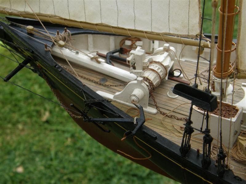
The windlass was constructed of wood with smaller details made from plastic, Photo 10.
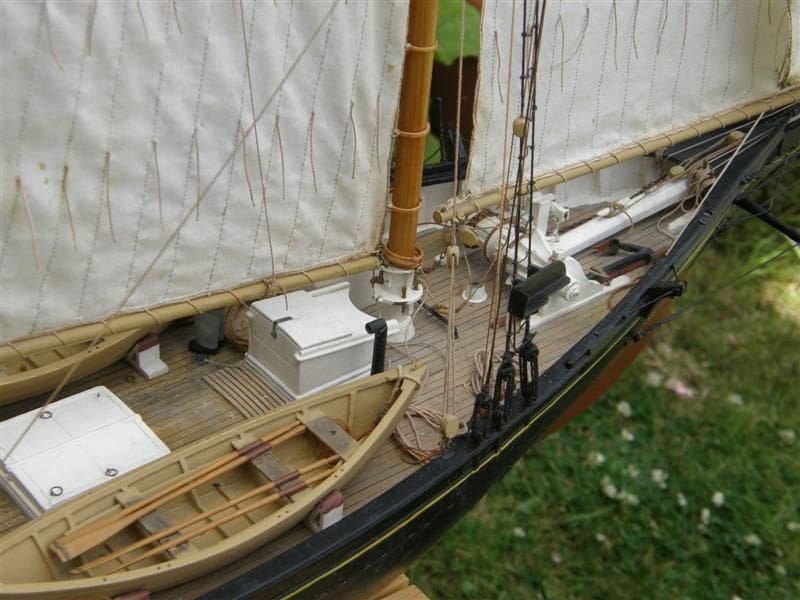
The hatches were made to open, the openings having a coaming all round with a gap between it and the planked deck, Photo 11. Each hatch rim was made to drop into the gap, apart from the forward companionway hatch which is stuck to its own hatch, this being an oblong of deck planking. Access to the battery switch is underneath this particular hatch.
The mahogany chest forward of the crews quarters and behind the after hatch has two holes under it so that the mounting screws of the forward servo can be reached if necessary.
The stove pipe was made from wood with a copper sheet top in the shape of a tube, Photo 12.
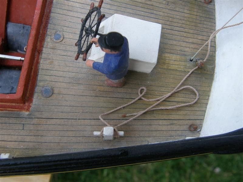
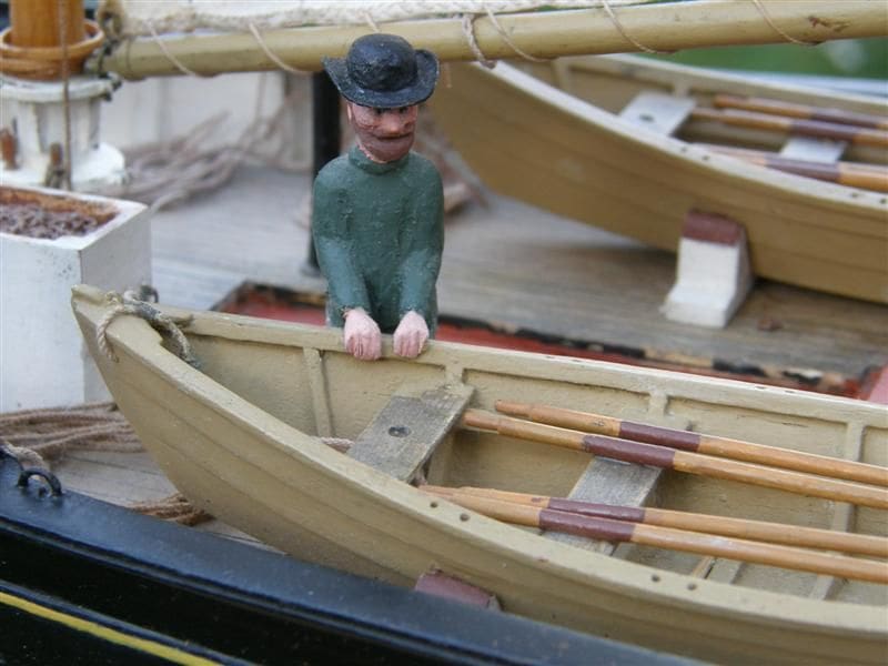
The crew were carved from blocks of hardwood apart from the brim of one of their hats which was made from Bristol board, Photos 13 and 14.
Belaying pins were turned in brass on a small lathe.
The anchor slung over the side of the bows was made from plastic with a brass stock and the anchor on the deck is of plastic with a wooden stock. The anchor chain I handmade using pointed pliers to bend each link to shape. The chain box has a false shelf in the top of it, with a thin layer of chain glued over it to give the illusion of a box full of chain.
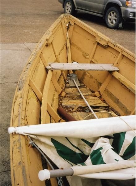
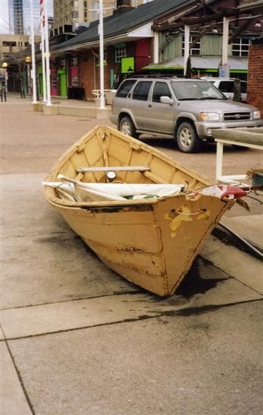
The dories had their ribs and bottoms cut from thin wood (I am not sure of what type) and the planks from Bristol board. I obtained the plans from: The Dory Model Book by Dynamite Payson. Other information was obtained from the Lettie G. Howards own dories, if you refer back to Photos 1 and 2, plus a dory that I located in Toronto, Photos 15, 16 and 17.

The Pumps had their handles made from brass, and the remainder was from wood.
Rigging. To overcome the problem of finding the correct scale and colour of rigging cord, I made a small rope-making machine and used Sylko in various colours, Photo 18. Sylko is very good for the purpose in that it has a slight spring to it and does not go slack.
Blocks. Those for the throat halyards and similar blocks were carved from wood. For the others I carved one of each size in wood and used these as masters to make castings of the rest. Moulds were made from polyvinylsiloxane, which is an impression material used by dentists, but is also sold by some craft shops. For casting the blocks I used slow setting Araldite, but any slow setting epoxy would do, but I have used Araldite in its various forms for many years and like to use that which works well for me. The detail of the Araldite castings is almost flawless and the deadeyes were made in the same way.
The sails
A white nightie makes excellent sail material and it is also not liable to shrink due to washing, so when the time for making the sails draws near my wife knows what to expect!
First, I drew paper templates for the sails and cut the material to shape, making allowances for the hem. These were then rolled into the sail proper and stitched by hand using the smallest running stitch I could manage in grey thread. The bolt ropes were stitched in place with brown thread on to the starboard rather than the port side, Lottie S. Haskins being an American ship. I could find no evidence of strengthening of the sails, so left them plain and the reefing points were reinforced with glue where they went through the sail.
The completed masts are shown in Photo 19 together with the mainsail attached to its mast hoops.
Colour scheme
I do not know in which colours Lottie S. Haskins was originally painted, except that her bottom would have been brown. Brown copper paint became the standard anti-fouling paint at Gloucester in 1880 and the name in the scrollwork at the bow would have been yellow. When first launched, ships were often painted in various bright colours, but this rarely lasted after a few months of rigorous service. Even so white was always popular on deckhouses and hatches, being readily seen at night. After 1895, colour schemes employing black, white and on occasion blue and grey became normal. So I gave the model the prime colours of black and white using satin Humbrol paint. The names were not as difficult to paint as one might imagine, as I incised the letters into the wood, painted them, and then wiped off the excess pain.
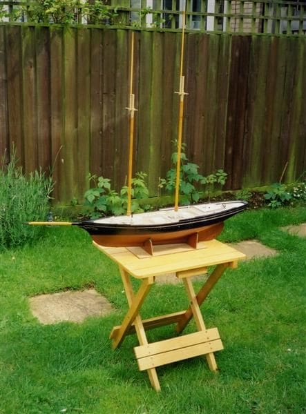
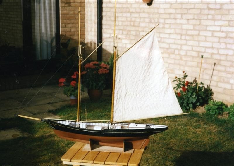
The completed model is seen in Photo 20.
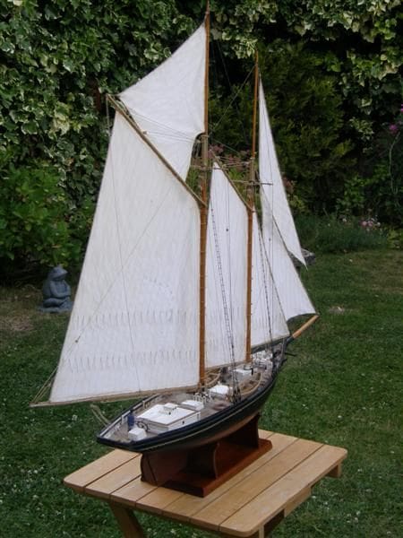
I read somewhere that if somebody wants to own a favourite sailing boat scaled down to a smaller size, it cannot be readily done because of the fundamental laws of scale in naval architecture, such as loss of stability. This must certainly be true of many scale model yachts, hence false keels. However, with my model I seem to have got away with it fairly well. She sails very well indeed and is very fast in a moderate breeze, but cannot cope with sudden strong gusts, although she sails normally when they are over and not long ago she appeared on a local television program. I rather enjoyed seeing her sailing on television!