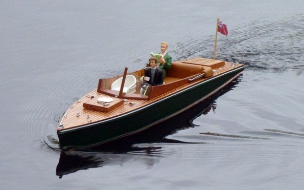
Lady Beale
JOHN ELLIOTT reviews the Deans Marine slipper launch
Enjoy more Model Boats Magazine reading in the monthly magazine.
Click here to subscribe & save.
I first saw this kit on the Deans Marine stand at the late May 2010 Mayhem weekend at Wicksteed Pleasure Park. It was a model that instantly appealed to me – polished wood and the thought of a leisurely cruise with a picnic on the Thames! Ron Dean was kind enough to give me a demonstration and offered our Editor a kit for review. The model is based on the Thames launches that were constructed in the 1920’s (the roaring twenties). The slipper hull was designed to reduce the wash and help eradicate bank erosion. Apart from the kit you will need a motor, coupling and propeller, best purchased at the same time as buying the kit as well as r/c, battery, glues and paints etc.
The kit
The two main components are the hull and deck which are well made GRP mouldings. The planking is supplied cut to width in mahogany and obechi with balsa and ramin sections for the deck supports. A tray of fittings contains white metal and resin castings together with a propshaft and tube plus miscellaneous items such as cord. The seats, canopy, motor mount and battery trays are vac-formed mouldings. A pack of printed vinyl is supplied for the cockpit floor and sides, along with dashboard and nameplate items. Printed plastic sheets complete the kit hardware. A full size colour plan accompanies a detailed instruction book which contains step by step construction details with pictures, recommended running gear information, a painting and glue guide, plus useful hints and tips. For an additional purchase of £2 (plus supplying a blank sealed CD), there is a Photo CD available containing 400 pictures taken during the construction of the prototype. The kit I received was from the first manufactured batch. Deans Marine normally sells these at a reduced price with the anticipation of getting feedback on any areas that might need modification to the kit or improvements to the documentation. In fact whilst I was with Ron Dean he received a phone call from a purchaser who was having a problem with water ingress through the rear hatch when the model was driven hard astern. This was not surprising as the stern is only just above the water, but Ron has taken this on board(!) and now has a recommended solution.
A stand
This is the first and most essential item to be made. Material for this is not included in the kit, but there is a template. I made the stand from 6mm MDF and two short lengths of dowel. It is worth making this first as it helps so much during the model construction. The instructions then take us on into the basic hull construction.
The hull
Worth bearing in mind is an oiler pipe soldered at right angles to the propshaft tube. If the propshaft tube is installed with this pipe pointing vertically upwards, it will foul the underside of the cockpit which drops into the hull through the deck opening. So, it may be better to angle it to one side (or even horizontally) and connect a piece of silicone tube to it. A small bolt inserted into the end of that tube will prevent any oil escaping.
Rudder
Masking tape helped retain its position whilst a couple of spots of superglue served to temporarily hold it all in place. A short length of plastic tube secured to inside the hull bottom around the rudder tube created a coffer dam into which slow setting epoxy was poured to make a nice neat and robust installation.
Rudder servo
Whilst we have a nice open space and before the deck is glued on, it is best to make the mount for the rudder servo. Note the position of the access hatch and check clearance between the tiller, servo arm and deck moulding. A mini-servo is all that is needed which was installed in a small box laminated from plastic card with a removable lid retained by two screws. This box was glued to the hull bottom and the servo can easily be removed for maintenance. The tiller arm supplied is a metal casting, but for personal convenience this was replaced with a plastic version with a central brass bush for a grub screw permanent location.
Deck
A coaming was made for the two hatches followed by construction of the removable cockpit section.
Cockpit
What you need to aim for is a really snug fit of the cockpit through the deck access opening which will reduce the chance of water entering the hull around the edges of the cockpit. The individual parts for this were cut from the supplied printed sheet, each a little bit oversize. These parts were each offered in turn to the deck opening, checked for exact size and marked. They were then trimmed to size, double checking throughout this process. Once completed, the individual pieces were taped together with masking tape and tested for a good fit into the hull through the deck. Everything was then glued together, except the outside plastic retaining panels as I intended to replace these with mahogany as a personal choice.
Basic painting
The next construction step would be to plank the deck, but there would a good chance of ruining it when painting the hull, so this came next.
Once satisfied with your drawn waterline, a 3mm wide strip of low tack masking tape was applied which would represent where the red painted waterline would eventually be. This narrow 3mm tape was purchased at a military modelling show. The lower section of the hull then was masked with Tamiya tape and clean white paper, and the hull upper section then sprayed with several coats of Humbrol No. 195 Satin Green using a Badger 175 airbrush. It is best to remove masking tape as soon as possible to hopefully avoid a paint edge ‘ridge’.
Both sides of the 3mm wide waterline tape were now be used as a reference and masked up to each of its edges with tape. Then the original 3mm tape was removed exposing the narrow waterline to be painted red. As it is quite narrow, brush painting is okay for this task. Once the paint was dry, all the tape was removed and the final coats of satin varnish could be applied by airbrush. Ronseal satin polyurethane varnish diluted 50:50 with white spirit thinners was my choice. It is best to stress that all paints should periodically be tested for compatibility and finish on pieces of card before actually applying to the model.
Deck planking
The king plank position was marked out onto the deck, cut to fit and glued in position followed by alternate strips of wood until the deck was totally covered. On the more difficult pieces that are curved at both ends, it is easiest to get one end fitting perfectly and then carefully mark the other end before cutting.
Hatch covers and painting
The hatch covers were made from plastic to create formers and covered in wood planks superglued in place that matched the style of the deck planking . The deck and hatch covers were lightly sanded until level and smooth. To varnish these, a cloth pad soaked in satin polyurethane varnish diluted 50:50 with white spirit was used for applying each of the first six coats. Each coat had a light sanding before another was applied, the thinned varnish soaking into the wooden deck very nicely. The final finish you obtain will depend on the number of coats and effort applied.
Back to the cockpit
All these individual parts were now removed, painted and then permanently fixed in place so the cockpit was now finished. Fortunately the model is 1:10 scale so 1:12 doll’s house figures seemed to fit the bill. The two that I was able to obtain were made from resin and well detailed, costing around £5 each and the only concern was that they might be too heavy, so some lightening holes were cut in their bottoms! All that was left now were the deck fittings.
Deck fittings
The metal ‘chrome’ ones were painted with Humbrol Polished Aluminium Metalcote which can be polished when dry. There are quite a few extra ‘choice’ fittings and these were not all fitted, the horns and cowl vents in particular being omitted. It is best to insert a locating pin in the base of fittings wherever possible.
Radio control
The receiver and esc are located under the forward deck with the on/off switch fixed underneath the forward hatch on a removable platform. A six volt drive battery is suggested but as a couple of 7.2 volt sub-C buggy packs were in stock I thought I would try to fit one of these into the model. It could be fitted as a single unit – just, but to ensure a better balanced model, the pack was split into two sticks of three laid either side of the motor and secured with Velcro. Suppliers The Component Shop can supply bespoke packs if required.
On the water
The Deans Marine prototype had performed well at Wicksteed Park and so did mine now, six months later! It responded well going from a steady realistic cruising speed up to one where a large bow wave was generated. It was a little deep against the waterline, probably due to the weight of the battery and figures. Going astern is okay, but caution is needed to keep the speed low as too much and the stern will submerge. Turning to port and starboard was fine and it has the makings of a good steering regatta boat.
Improvement and conclusion
This is an excellent kit of a nice subject with scope for personalisation. It will fit into any car easily, is light in weight and therefore easy to manage. Building is relatively straightforward so it is recommended for beginner and expert alike. The price of the kit is very competitive and it is excellent value for money. The instructions are comprehensive and to those new to the hobby and thinking of buying this kit you always have reassurance of direct help from Deans Marine. Price is £120 at time of writing.
Major additional items used in this model
Coupling: Nycrome EX/L 2.3mm/M4 from Deans Marine.
Propeller: Raboesch 162-11 from Deans Marine
Battery: 6 off 2600mAh tagged AA NiMH cells from Component Shop
ESC: Mtroniks Viper 15 Amp from Howes Models
R/C: Spektrum Dz6i form Howes Models
Plus glues and paints of your choice.


