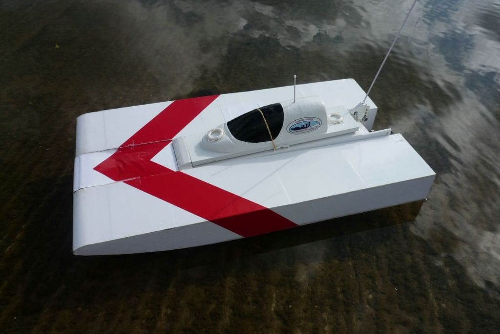
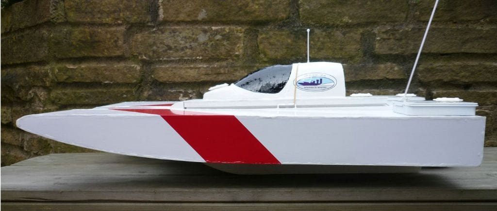
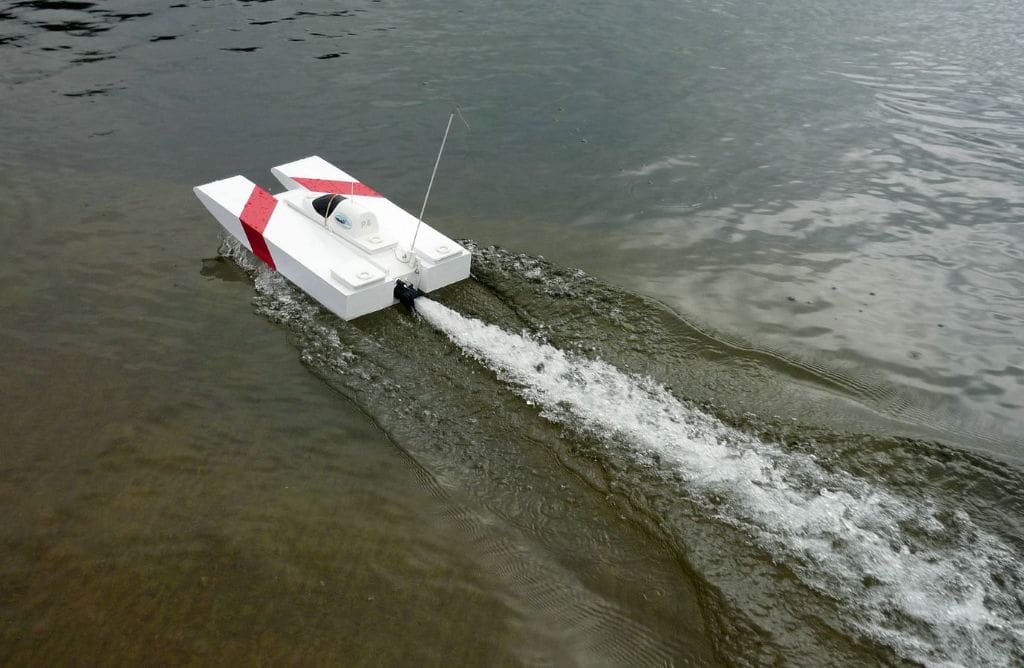
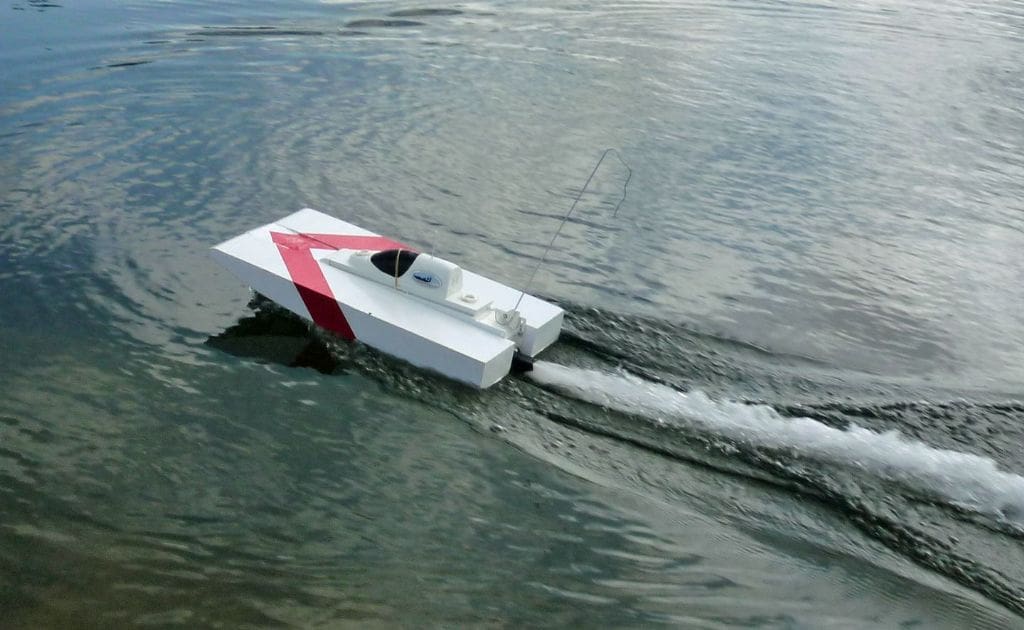
BRIAN JOHNSON with his hybrid water jet airboat
After too many years away from modelling and the newly found availability of a local sailing club, a return to model boats early in 2007 seemed a good option so it was off to the model shop for the first of many visits. With nothing particular in mind, but preferring a power boat kit with plenty of work needed, the Graupner Wiesel sold itself when the box was opened up. The building was not rushed so it was August before the first trials were made.
Around this time the Graupner Manhattan 74 build was featured in the Model Boats 2006 Winter Kit Special and this was saved as being an ideal next project. A full shopping list was compiled in the September, but this kit then became unavailable. Having set my mind on this particular model I had no notion of what to do next but Glynn Guest’s Skimmer Airboat in the September issue of Model Boats struck a chord and the result has been the series of airboats designed and made from October 2007 through to January 2009 with the completion of Speed-Skim.
Enjoy more Model Boats Magazine reading in the monthly magazine.
Click here to subscribe & save.
The Manhattan 74 kit became re-available early in 2009 and I was sorely tempted to dig out the original shopping list, but scratch building was now well established so something similar was required. The Wiesel triple screw and rudder configuration was prone to weed problems and a large part of the appeal of airboats is their total disregard of any floating obstructions. This was also part of the Manhattan appeal with its twin water jet drives so the concept of a self-build single water jet model was selected. The amount of immersion of the water jet outlet for optimum performance was unknown, but total immersion was thought probable as the centre line of the outlet is only 30mm above the water inlet grille in the base of the hull. Also the full size jet-ski’s have fully immersed outlets.
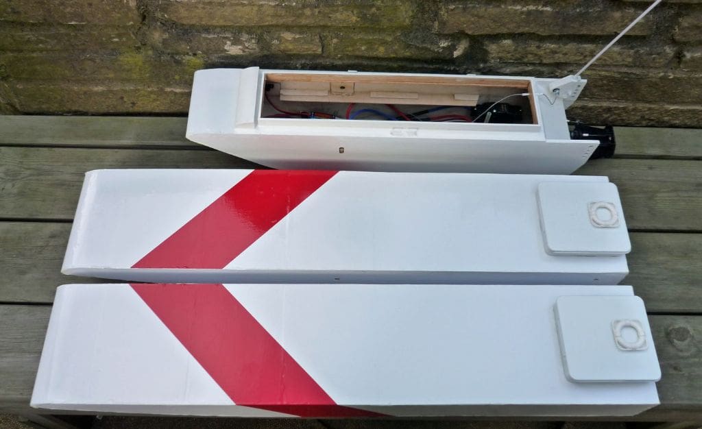
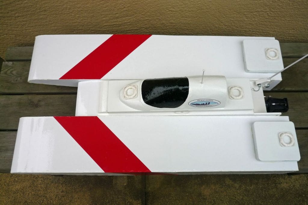
Due to the uncertainty of the jet outlet height it seemed feasible to make a boat with the outlet height adjustable so the drive and all the electrical gear became self-contained in a small narrow hull with sponsons bolted on either side to provide height adjustment as required. The combination of conventional hull, albeit small, for the jet drive with sponsons based on the Skim Airboat series is admittedly unusual but as an experimental boat the sponsons could be easily and cheaply changed for smaller ones later if thought beneficial.
Jet-Pack
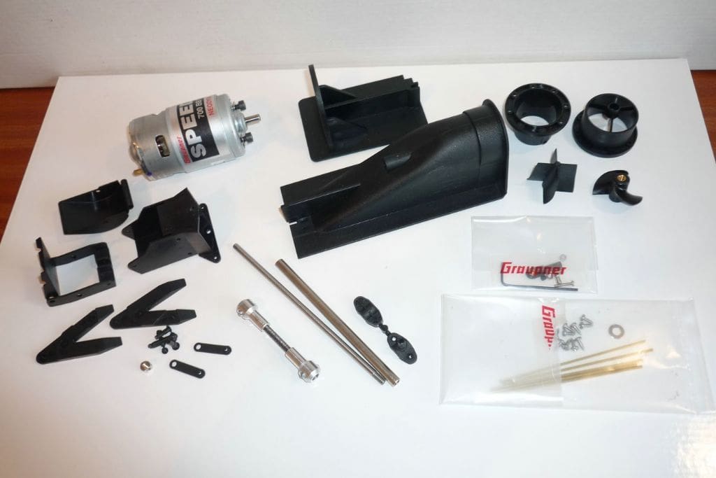
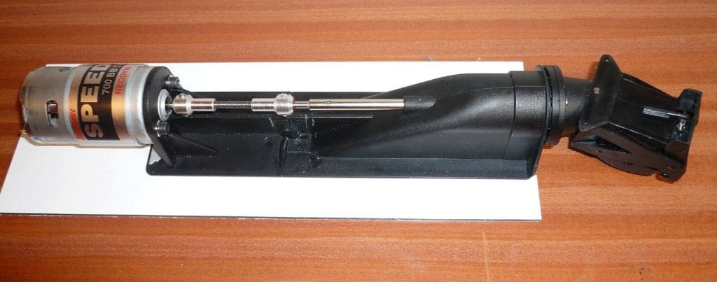
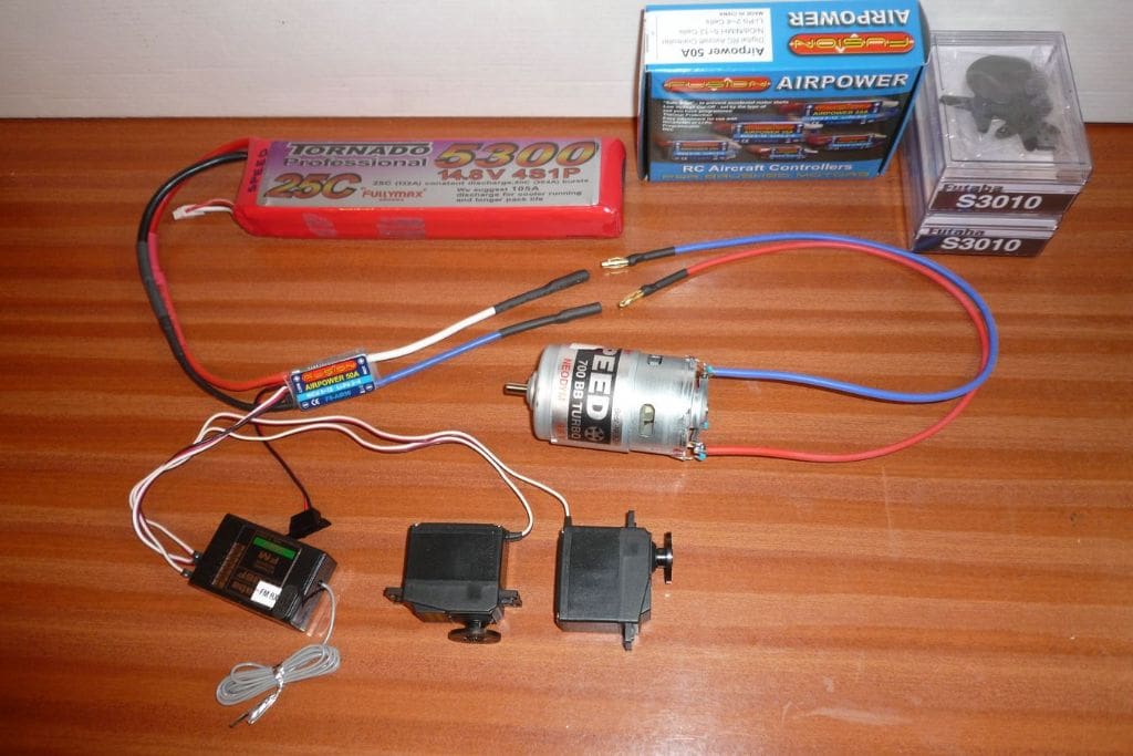
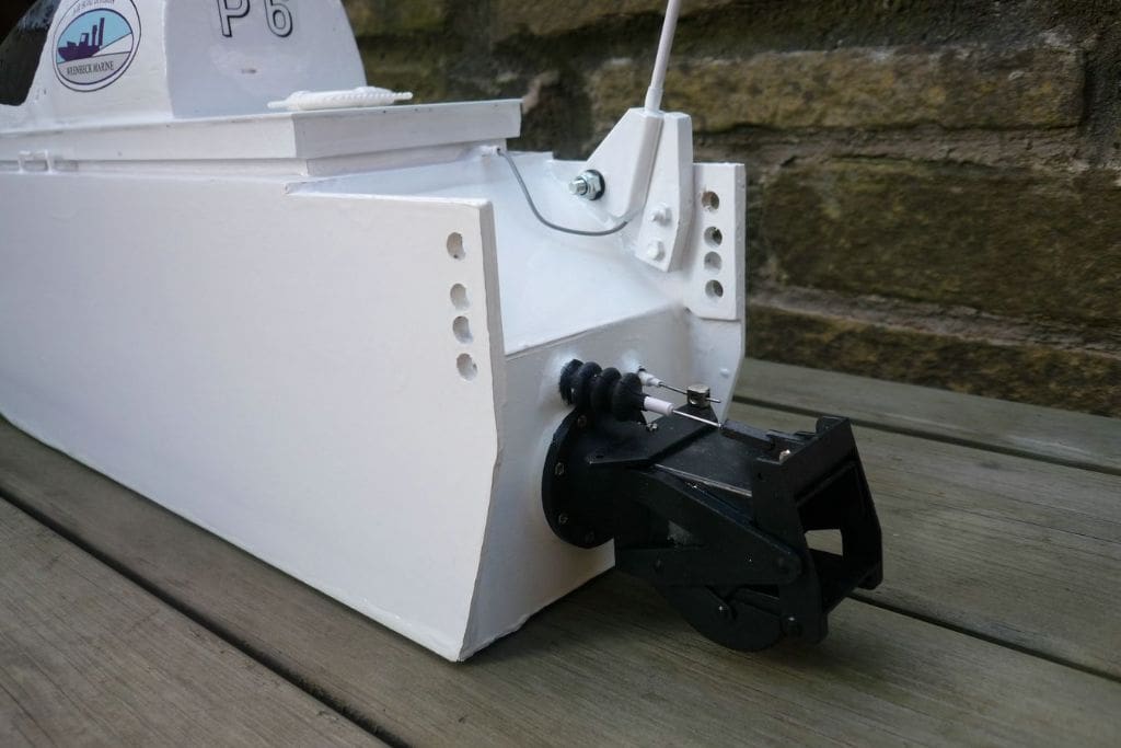
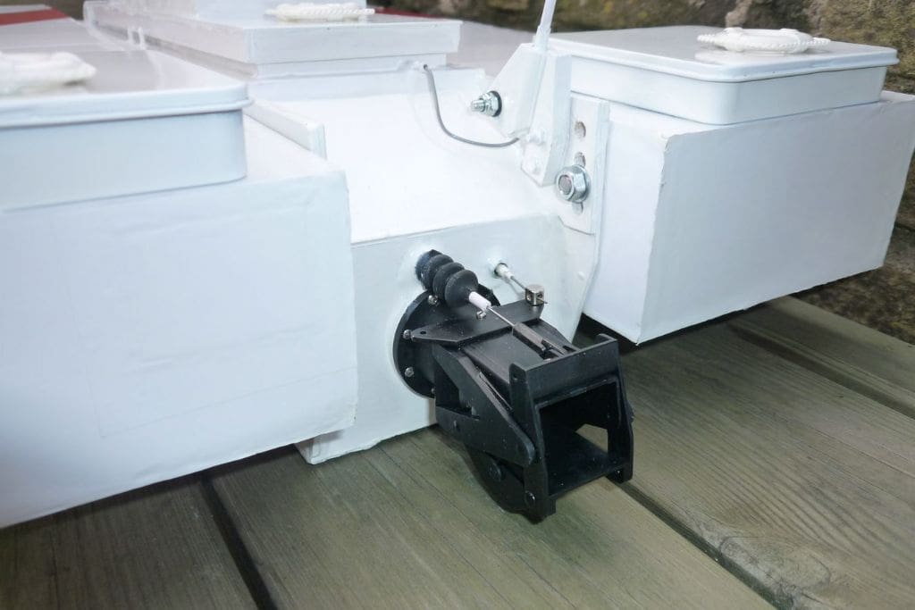
The actual central section of the hull I have called Jet-Pack as it is a self contained unit. With the sponsons added, it becomes Jet-Skim and this enables future experimentation and development. These sponsons are bolted on to aid testing and modifications. A Graupner Jet Propulsion Unit 6 kit was obtained, along with a Speed 700BB Neodym motor for extra performance. As this unit is the prime reason for the model the costly motor mount was added to the list to enable quick assembly and decisions on the hull design. The Graupner Jet Propulsion Unit assembly was easy, but care must be taken when pushing the prop. tube through its rear support as the tube bells out slightly to take the bearing and the tiny support stays are easily broken; mending is possible, but not to be enjoyed!
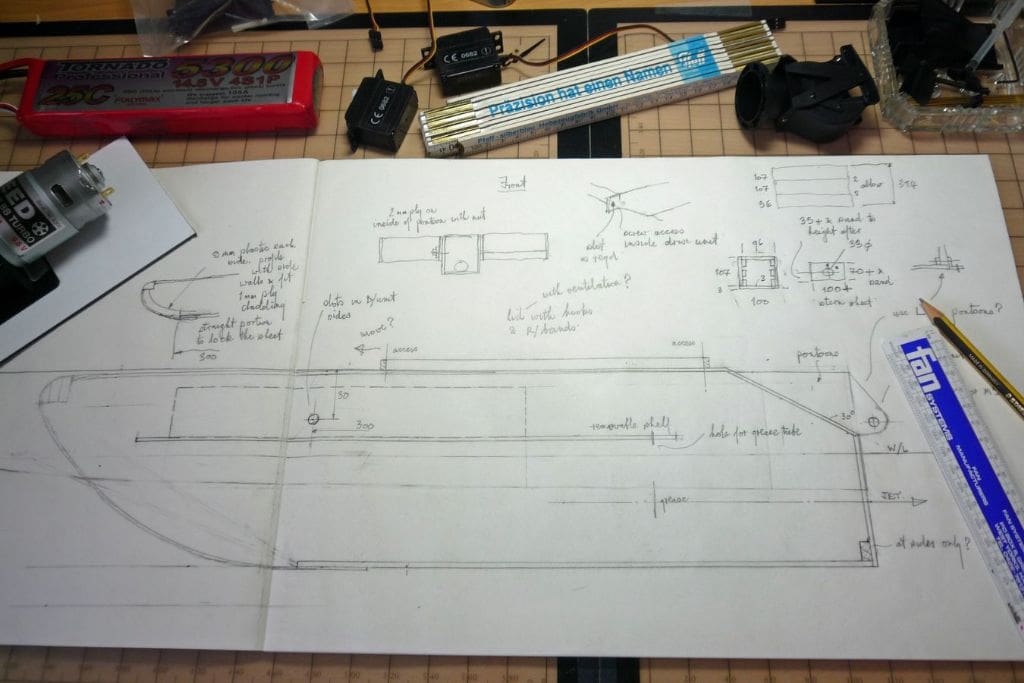
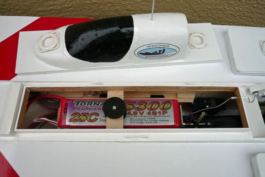
The starting point for the hull construction was a 3mm aluminium composite base plate, although plywood would be suitable. This was 300mm long by 100mm wide, with a long slot to suit the slightly raised area of the unit base. This width just allowed room for the intake end of the unit and side saddle servos for steering and reverse. At this early stage the drive unit was fitted to the base plate and epoxy resin used inside and outside to ensure good sealing. The hull height was settled by the fitting of a removable battery shelf just above the motor and room for the battery and its clamp above the shelf. This gave an overall height of 110mm and 2mm plywood was used for the sides and the deck. 1mm ply is sufficient for the curved portion from the front of the base plate to the balsa nose and with the stern plate fitted the overall length came out at 510mm. Short front and rear deck portions allowed a 340mm long coaming and hatch for good access. Now having a basic, but finished hull all internal joints were checked for any further sealing, before fitting out commenced.
The 2mm battery shelf was made narrow enough to be easily removed and has end stops plus side guides to suit the 14.8v 5300mAh LiPo battery. A screwed clamp plate between the battery and deck underside allows the battery and shelf to travel 90mm when later setting the C of G.
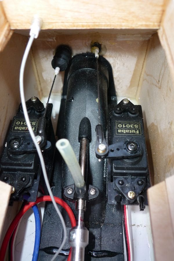
The next important task was to install and connect the servos and trays to the unit. Futaba S3010 6.5 kg/cm servos were obtained instead of the less powerful and more usually used S3152 variety due to availability; actual servo power required for all the airboat servos has not been established and probably smaller and less powerful ones would suffice.
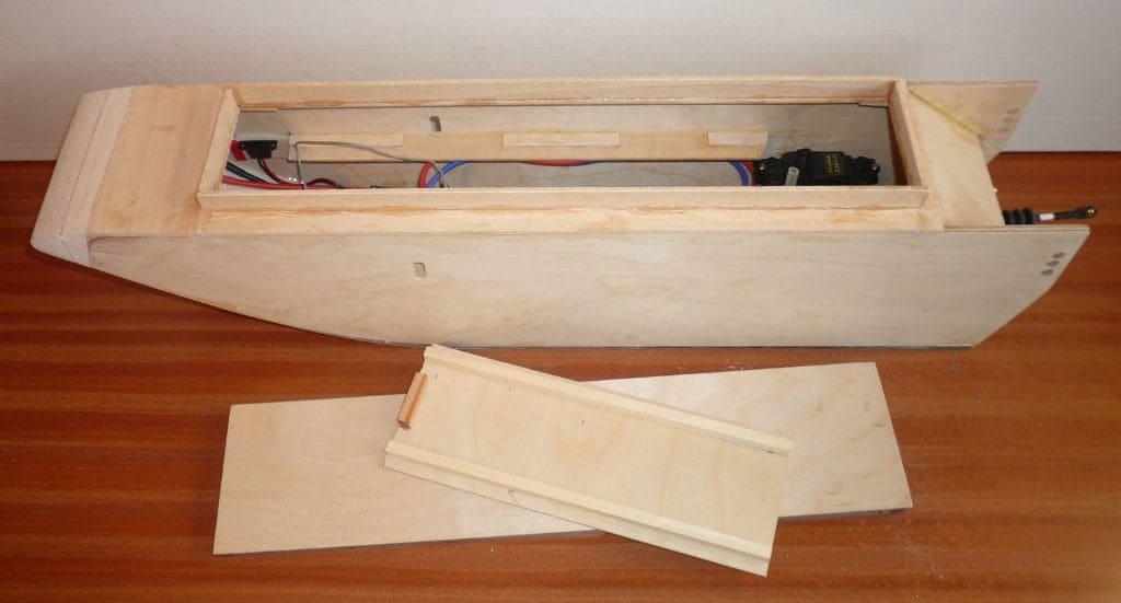
The only way to match the steering nozzle and reversing bucket travel requirements to the actual servo travel was to draw a full size plan and elevation to show the full extremes of usage. The steering is easily fixed by setting the radius, but the bucket is either open or closed so only half of its servo travel can be used; also the two holes in the transom must be carefully located to allow free travel through restricted watertight tubes. The steering servo tray was mounted hard against the hull side at a height to give a horizontal connecting rod. Ideally the bucket servo would be mounted to allow the connecting rod to be central in the boat and level in height, but its transom hole and sealing would foul the circular flange of the drive unit, so its tray sits hard against the side of the drive unit and 12mm higher than the bucket connection. With an internal bellows and plastic sleeves for the steering and an external bellows and sleeves for the bucket plus an injection of grease, the connecting rods travel safely without undue flexing.
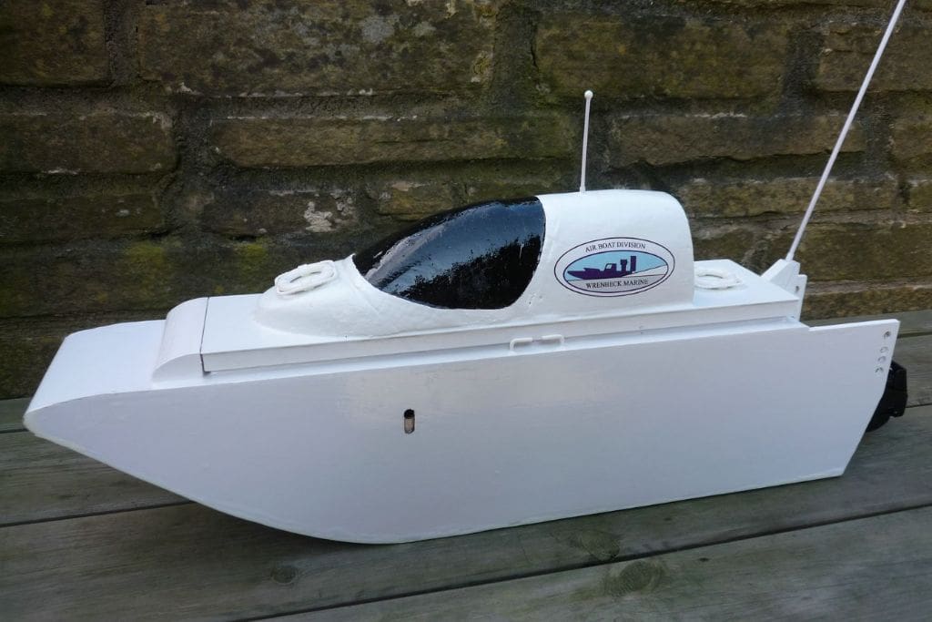
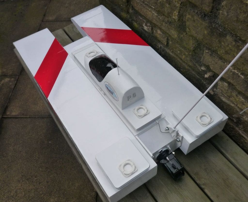
Space was available above the stern for a fold-away aerial so the wire was lead through plastic tube and it lies alongside the coaming when not upright in use. Holes were also drilled through the sides for mounting and adjusting the sponsons. The 1mm ply hatch and modified foam cabin from a model aircraft is secured by hooks and rubber bands to give a near watertight seal.
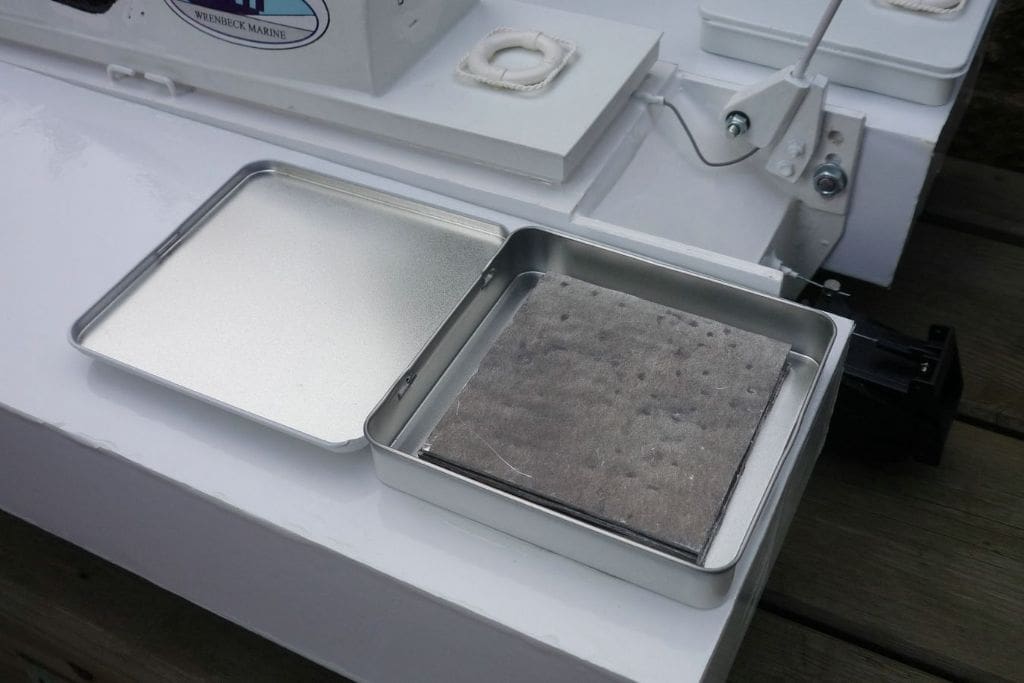
After two coats of 50/50 dope/thinners the Jet-Pack hull was covered in white vinyl sheet ready for a bath trial in the hope that this would give pointers to the design of the sponsons. I assumed that this small hull with a weight of 1830 grams would immediately rest on the bottom of the bath, but in fact it floated level with the centre line of the drive unit. This meant that the weight of sponsons, or something else, would be required for deeper immersion so two 415 gram tins of soup were placed on top which nicely immersed all of the outlet. The hull, without the hatch, was very unstable all this time due to its narrow width and it inadvertently keeled over. This flooded the hull and ruined the 50 amp non-waterproof esc so this proved to be an expensive bath test and it came to an abrupt end! However, a new esc proved that all the other electrical gear was not adversely affected.
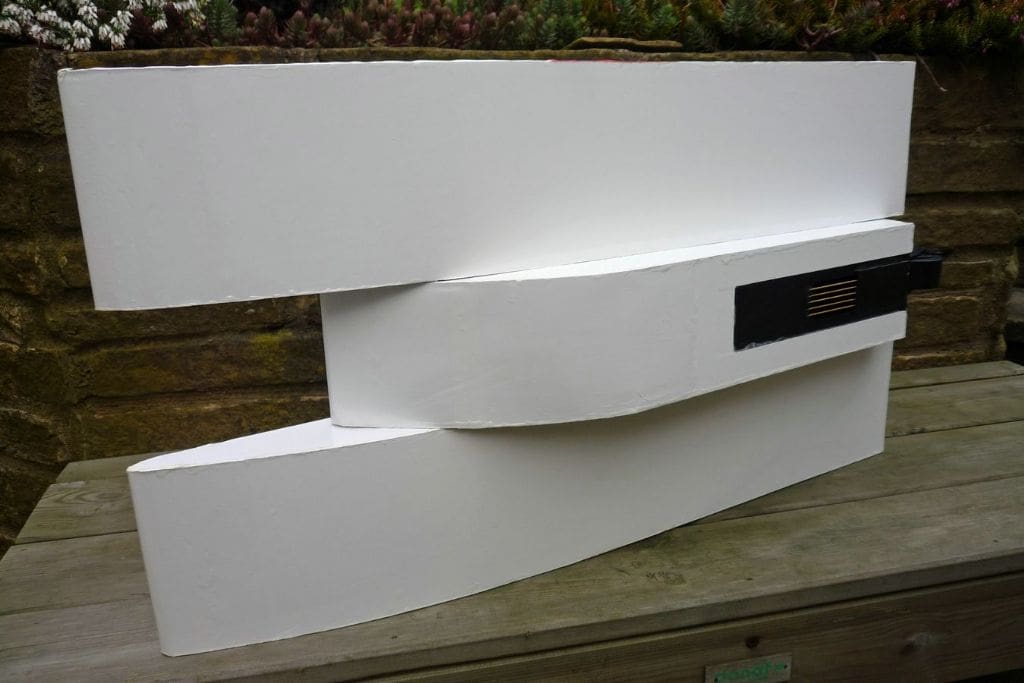
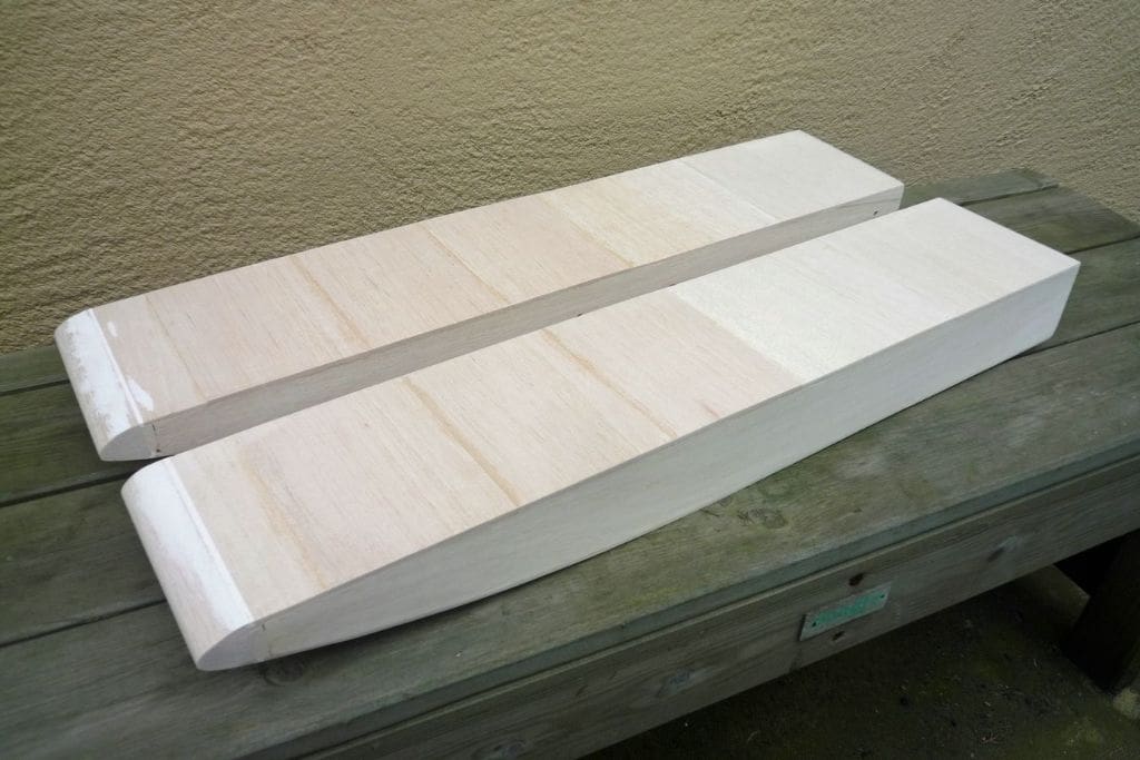
The sponsons
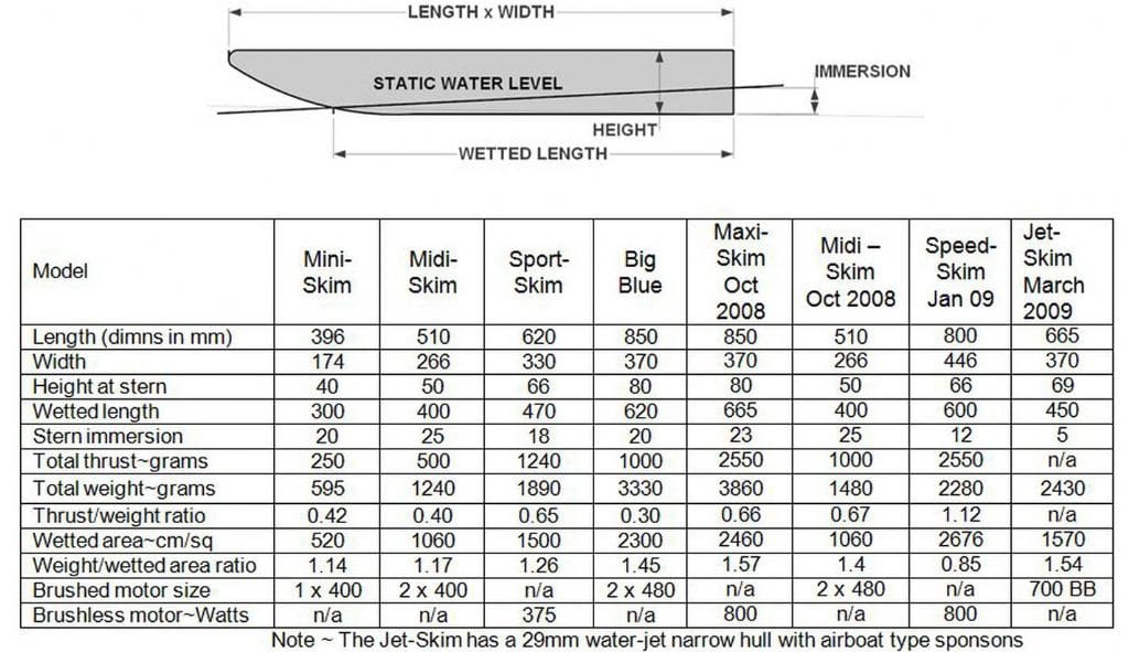
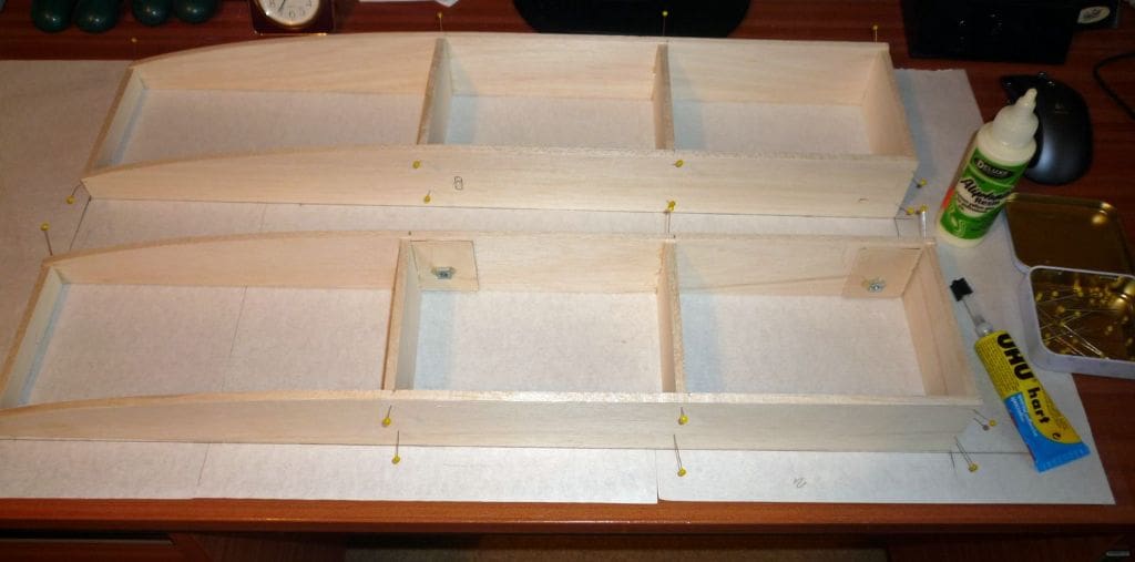
Being an extension of the original airboat thinking and having no other experience to draw on, it seemed reasonable to use the previous parameters for weight and wetted area. The supposition that the hull, or sponson, weight could be say 50% of the hardware weight was obviously irrelevant as the sponsons were to be balsa boxes only. The balsa allocated weighed in at 300 grams and this plus the Jet-Pack at 1830 grams was used for the calculations. This total design weight of 2130 grams at a fairly safe 1.3 grams per square centimetre gave 1640 sq cm wetted area. The fact that the pack floated during the bath test showed that its wetted area had to be taken into account, so 400 sq cm was used based on a 100mm wide hull and an estimated 400mm wetted length. This left 1240 sq cm for the two sponsons. A guessed wetted length of 500mm gave 248mm width and actual finished widths of 130mm each.
After making and covering the sponsons using 6mm balsa with 3mm balsa top and bottom and white vinyl sheet overall and M6 captive nuts inside, they were secured to the Jet-Pack ready for a bath test. The sponsons total weight had somehow increased to 450 grams and the total boat weight actually finished up at 2430 grams.
The airboat design philosophy is minimum weight with maximum thrust and this model brought up the alien word of ‘ballast’ to force (if required) the total immersion of the jet unit outlet. Four pieces of 75mm square lead sheet were added to each box (total lead weight of 870 grams) on the rear of the sponsons and the flotation test gave promising results of full jet outlet immersion with a dead level Jet Pack, 450mm wetted length and 20mm rear sponson immersion. All of that was in line with typical airboat results, but with a total running weight of 3300 grams. A tethered power run gave a good surge of water and future runs and performance comparisons with the earlier airboats were eagerly anticipated.
Subsequent to the bath immersion test, doubt was thrown on the optimum working level of the jet outlet. An internet report showed that all the thrust is generated within the jet unit irrespective of its location relative to the water level and that full immersion is actually less efficient due to the higher density of the water it is discharging into. Also Graupner appear to locate the outlet centre line on the static water level. In model terms there is nothing critical regarding the location and I was happy to follow the Graupner mode of use and ditch the 870 grams of ballast. A final immersion test showed a dead central outlet in the water but with a slightly bow down attitude which would disappear under power or a small amount of ballast could be fitted if found beneficial. In actual day to day boating the advantage, or disadvantage, of any minor adjustments is difficult to quantify and may well be affected by the conditions of the day. If the bath test is satisfactory then the first runs will be the same and any thoughts of fine tuning disappear whilst the enjoyment continues.
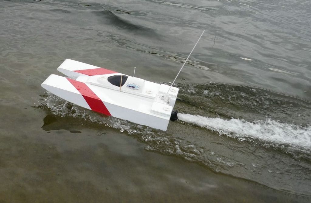
Jet-Skim testing
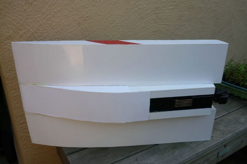
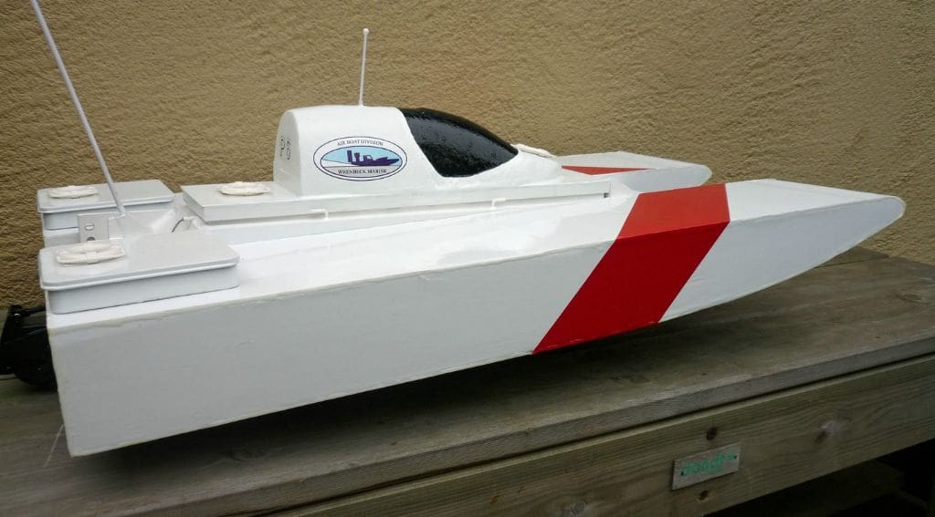
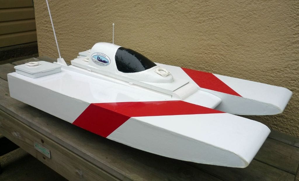
The bluff front of the central Jet-Pack power unit tended to push the water instead of riding it and this limited the use of full power. A curved nose from the flat underside of the central Jet-Pack to the sponson nose level would I reckoned help to streamline this area and allow more throttle. Apart from this the model ran very well and was totally stable even when turning within its own length; aesthetically the sponsons were too obtrusive and if curved outside from their mid-length to say 50mm wide at their front edges, this would improve the looks without affecting the performance.
To take full advantage of Jet-Skim’s potential it was decided to streamline the nose of the Jet-Pack by adding 0.8mm plywood extensions to take its nose to the front edges of the sponsons. This looked okay, but a bath test showed that water was filling the void between the existing bluff front and the new forward edge so this space was filled with polystyrene foam and the external seams covered with waterproof tape to solve the problem. Also, lifting the pack between the sponsons by using the bottom fixing holes brought the jet centre line virtually on to the water level and the base of the sponsons were then just resting on the water. As only the Jet-Pack base was immersed up to the jet centre line, the performance had to be very promising and the later trials have proved it to be fast and responsive. On this type of small fast model the reversing bucket is of little use, but it would suit a larger and statelier model along with bow thrusters for full effect.
This hybrid model may look incongruous and is hardly graceful, but as an experiment it has been very successful in paving the way for other water jet boats.
The making of the series of airboats through Mini, Midi, Maxi, Sport, Speed and Jet-Skim has been a natural progression with nothing planned. Each variation has thrown up an attractive alternative and now true to form, Jet-Skim offers the possibility of a twin drive version in a compact shallow vee conventional hull so giving twice the thrust with reasonable extra weight depending on the materials used. The basic drive unit is plastic, the same 14.8v 5300mAh LiPo battery can be used so the second motor could be the only weight penalty unless ballast is needed to centralise the outlet on the water level.
(In February 2008 MB, Brian had a letter published in Mail Boat about his airboat development of the original Glynn Guest Skimmer Free Plan first published in September 2007 MB. This was then followed by excellent practical in depth articles in the July 2008, November 2008, May 2009, September 2009 and January 2010 issues of MB. He is to be congratulated on his practical, well thought out and written development of the original Skimmer design – Editor)


