Irishman
IVOR WARNE reviews the recently updated Model Slipway kit of Yorkshireman and Irishman
Enjoy more Model Boats Magazine reading in the monthly magazine.
Click here to subscribe & save.
This is not a new kit, but the updating of an old friend to the latest kit standards. First, just in case you think I have got it all mixed up, the Yorkshireman kit from Model Slipway can be built as Irishman, which is what I have done. Why? The original Yorkshireman, the first in the Model Slipway range dating from 1990 has remained a firm operational favourite in my fleet during the interim and as it still exists, the new kit was built as Irishman.
I was intrigued to see how an already brilliant kit could be improved. There was also the question of my building ability. Has it improved in 20 years or had the passage of time affected my eyesight and dexterity? To decide, you will have to read the whole article and I am including pictures of both Irishman (the new model) and Yorkshireman. So after a year of model making, here goes!
What’s new?
Improvements:
1. The plans are now to scale.
2. More isometric step by step exploded drawings and less words in the instructions.
3. The RIB and BOTI boats are now resin items rather than vac formings.
4. The running gear is now more robust (but slightly less true scale) and the propshaft tubes run into the Kort nozzles, so are much easier to set up.
5. Commercial plastic propellers replace the previous white metal supplied versions. Model Slipway can also supply brass propellers at additional cost.
6. Brass rudders are now used as the basis for the steering gear rather than the white metal versions previously supplied. Having said that, the 20 year old white metal ones are still working perfectly.
7. The etched brass fittings sheet has been revised and is absolutely brilliant.
8. Plastic (styrene) parts are now CNC cut 1.5mm rather than diecut (like the other recent kits from Model Slipway) resulting in more accurate and easy to assemble individual parts.
9. The waterslide transfers have been replaced by self-adhesive vinyl. These should last much longer than those on my original 1990’s model, which have peeled off and disintegrated.
10. The new model now has the correct number of seven bridge windows instead of six as in the original kit.
CNC plastic sheets
A few words about these. The parts on the main sheets are now milled to shape and are easy to cut out with a sharp Stanley knife, trimmed as need be and sanded to exact size. You know when the exact size has been achieved when the milled edges finally disappear. CNC parts means accuracy, which thus means the kit MUST go together. If not, then it will be down to you!
Hull
To accommodate the anchor stocks, a 3.5mm hole needs to be drilled in the top of the recesses which is much easier to do before putting the foredeck in place. To locate the anchors in the finished model, a short piece of plastic tube slides over the top of the anchor stocks so that a cross pin can be inserted to hold them in place, Photo 2. Dry fitting everything before the foredeck is glued in place is wise. It will be easy to seal around the 3.5mm hole later as there is good interior access for nifty fingers.
Running gear
Templates are invaluable and with a twin screw model the shafts need to be parallel and aligned, which is an obvious statement, but can be hard to achieve. From the plan, the shafts are 124mm between centres and so two templates were made with 4mm holes drilled at this separation. These were fitted to both ends of the shafts and temporarily locked in place with nuts. The position of the holes in the hull for the running gear and the dimensions are in the instructions, and will need to be carefully transferred. Marking on standard auto masking tape applied to the GRP hull is a lot clearer than drawing directly onto the hull and it stops the drill slipping and perhaps the gel coat flaking, Photo 3.
Once all is set (shafts, kort nozzles, fairings) the propeller templates can be removed. It is vital to crop off and sand flush any intrusions into the nozzles created by the white metal locating pins. I forgot, and this presented a bit of a challenge when the model was completed, but fortunately with a happy ending. The motor mounts are from 1.5mm scrap plastic. The important bit, once the motors are bolted into the mounts, is getting the motor/gearbox output shafts properly aligned with the propshafts. I use a large diameter brass tube slid over the universal joints to hold them rigidly in straight alignment which is simple and effective, Photo 6. My habit is to ‘over engineer’ and further strengthening of the mounts was then performed with tissue and resin between the hull and motor mounting side plates.
Rudders
The rudder servo mount was made in much the same way as the motor mounts. On a twin rudder configuration like this, I prefer to run a servo rod separately to each rudder so that if one fails, I still have one rudder to get me back to the pond side.
Bow thruster
Having sanded the outside of the tube flush with the hull, the grills over the bow thruster openings were added, Photo 10.
Bilge keels
There are different ways of installing these. An easy method as adopted here, is to mark the position of the bilge keel on the hull and then drill 0.8mm holes along its length. Glue lengths of 0.8mm brass wire into these holes, lay the hull on its side and place the keel over the wires and glue in place, both to the hull and the wires. These wires are on the underside and cannot be seen and excess material can later be trimmed flush with the outer edge of the keel, Photo 11.
Afterdeck
The bulwark around the afterdeck is part of the hull moulding and should be filled and sanded smooth before inserting the deck which is much easier done now, rather than later. It’s also not a bad idea to draw a prominent centre line on each deck to act as a reference point for all future assembly. In this bulwark are four holes which are marked and need to be opened out. To make a nice inside finish to these, some spare white metal round portholes were squeezed to an oval shape and inserted, thus making the whole thing much neater.
There is an option to make cutouts in the afterdeck to allow access to the rudderpost tops and the instructions provide accurate dimensions. I added to these by putting a 5mm lip around the hole, the same as my 20 year old version. We are all aware of the ‘Law of Sod’, which says that if you do not have access, then sooner or later you will need it anyway! Photo 13 has everything clamped in place for gluing and a dry run before gluing is always a good idea. Some 6 x 3mm strip was used to beef up some of the joints between the deck, winch house and hatch assemblies. The deck break bulkhead (port and starboard) has to be positioned precisely and carefully trimmed to fit, Photo 14.
Main deck
Much the same as for the afterdeck with this item. Careful trimming and the coaming is best fitted before gluing the deck into the hull, Photo 15. Reinforcement was used under the coaming joints.
Portholes
These are marked on the hull. To open them out, drill a 4.5mm pilot hole at the centre of each mark and then file out to 6mm. If done carefully there is no need to use the white metal portholes supplied. For glazing, after the hull was painted, it was laid on its side, the inside of the openings sealed with masking tape (and the outside around the holes also protected), before pouring in ‘Solid Water’ which is a two part clear resin from Deluxe Materials. This product works well, Photo 16, but a steady hand is required.
Main deck bulwark
On the inside of the bulwark at its deck joint, some 0.5mm plastic strip was later added for strength (also make hand painting easier), then the bulwark supports were added which have to be cut from the printed sheets. It is good idea to remember to sand away the raised edge generated when cutting anything from styrene, before gluing in place.
Foredeck
This will also need to be trimmed to fit on top of the hull. Once again, draw a prominent centre line before doing anything. The foredeck bulwark will rest on the GRP moulding and butt up against the foredeck edge. Masking tape and weights held it down whilst the glue was setting, Photo 18.
Foredeck bulwark
This is not easy as it is curved and leans in 10 degrees, so some wooden blocks with the necessary 10 degree lean on their outer faces were prepared. The bulwark styrene was run back and forth over the workbench edge to put a curve in it which makes the task a bit easier. To start with, the central section of each side was glued. Next day the ‘free’ ends were glued to the forecastle deck edge/GRP hull using numerous clamps, Photo 19.
There are a couple of mooring ports in the bulwark and they should really have a profiled liner. Brass 13/64 inch eyelets superglued into place did the trick, Photo 20.
Bulwark capping
On the full size vessel this is solid and oval with a slight overhang. To simulate this, the capping pieces from the printed sheet were glued to the inside of the bulwarks, level with their tops. Then, 0.75mm square plastic strip was fixed around the outside of the top of the bulwark. When dry, this was all sanded to shape and also so that any joints were invisible.
The stern capping is an specially shaped part and needs a 0.8mm wires superglued to the inner edge, so don’t forget them please, Photo 21.
Hull fittings
The towing bow supports in the kit are of dowel, but clad in styrene tube, this being my lazy way of achieving a good finish. These were also pinned to the deck for further strength. The bows themselves are made of two pieces of styrene creating the arch, with the bottom piece being longer to fit under the bulwark. The anchor winch castings for the main gear needed a minor bit of fettling to fit together. A short length of rod ensured proper alignment of all the component parts, Photo 22.
Railings
.
It would be fair to say that if you do not like railings, then this is not the kit for you, as there are miles of them! Attached to the railing at the back of the HIAB deck are two spotlights on brackets. Those brackets need to be notched to properly locate and secure them to the railings.
Superstructure
The front of the superstructure is also a tight fit. The side edges will need to be sanded at an angle and there is only just enough ‘meat’ for this, so be careful!
The side vent doors at deck level either side of the superstructure are easy to make and fit, but need to have etched brass door furniture fitted and this is much better to do before fitting them to the main superstructure rather than later. The inside of the bridge looked a bit bare, so in went a map table with a map of the new water where I now run my boats. Whether those who peer through the windows with a magnifying glass will appreciate it all I just don’t know. Some BECC self-adhesive dials were added to the consoles together with a couple of pictures of radar screens (cut from a boat magazine) applied to the monitors. Wiring for the lights was run inside narrow box sections inside of the bridge, terminating at a chocolate block connector on the underside of the superstructure.
Superstructure fittings
The instructions suggest using scrap plastic to secure these wiring runs to the superstructure, but it did not look right. So, at each securing point some 0.35mm soft brass wire was fashioned into a sort of split pin and the legs popped through a 0.8mm hole in the superstructure sides (please see Photo 26 again) and secured with a blob of superglue inside. As a tip here, it is easier to do this sort of task whilst the superstructure is on its side and bubble wrap is as good way as any of protecting the other side. A second tip is to always to bend fine wire slowly. Some types have a tendency to fracture if the bending is done too rapidly.
Life rafts and radome
Vac formings? Well, I don’t get on well with any of these! Anyway, a central stiffener in the smaller halves of the life rafts make them rigid and therefore more amenable to being inserted into the larger halves of the raft, Photo 27. A 0.8mm pin through the underneath of each life raft and its mount helps locate each unit on the deck. The Radome was attacked in much the same way, but with a locating bolt in its base.
Spotlights
Solid Water from Deluxe Materials again did the trick for glazing, Photo 28. This is easier than attempting to glaze small circular or oblong openings with clear styrene.
Ladders and handrails
As for the waist-high handrails that are on the superstructure sides, these are just wire, bent to shape and pushed through pre-drilled holes. A wood spacer ensured that they were equidistant from the superstructure sides, before being secured on the inside with blobs of glue.
Wheelhouse roof fittings
First task is to locate the stanchions and bend the rails to match. The difficult bit is achieving perfect butt joints and then soldering the ends together, Photo 30. Bakers Fluid is still a great flux to use and if you have lead based solder in stock, that makes life easier as well. With care and heat shunts, no damage will occur to any nearby styrene.
Funnels and mast
These are just a pair of boxes joined at the top. The only thing to remember is that within each funnel, the top piece (Part 102) needs to be 8 mm down from the tops of the sides.
The etched brass navigation light bodies need to be carefully bent over a 5 mm diameter former to produce the oval shape required and the backs also need to be bent to shape. If the lights are to work, it is best to drill out the base first to take the wiring before bending them to shape. The light lenses were from clear plastic tube. The radar platforms are a strange shape, but easy to make. They have an edging strip that has to be bent to shape prior to gluing. Photo 31 gives an idea of how best to assemble them.
Cranes
These are of white metal and relatively heavy, therefore their deck locations were strengthened beneath with blocks of scrap styrene, On the Mark One version, the HIAB was assembled extended, but eventually, the stress induced by the weight of the arm caused it to fall apart. So this time it was assembled with an end resting on the deck – much safer.
Window glazing
Remove the glass from the slide mounts and score it with a piece of a broken slitting disc to get the size required. Special glass pliers (from Squires of Bognor Regis) are used to break the glass along the score line. Dry fitting is essential to make sure the glass is the right size. Care also needs to be taken that a finger print does not get left on the glass inside the model as it really does show. Canopy Bond adhesive from Five Star is as good as any as an adhesive, as it ‘grabs’ well and does not fog the glazing.
Power supply
The radio control units are all mounted on a base panel that can be moved from model to model. So this module can be used in different craft, thus saving on r/c equipment, Photo 33.
Painting
Marking the waterline is achieved by setting the model up on a large flat surface, such as the dining table, blocking up the hull so it is equidistant from the table top, bow and stern waterline mark, and then lightly marking the line with a pencil set on top of an adjustable mount. This can be homemade, or be one of those engineering magnetic bases designed to hold a vertical ruler and scribe, Photo 35, or something similar for different heights.
A few words now on painting the white metal fittings. There are a lot of these and they can get lost. So, the best way of avoiding this is to mount them on strips of wood. Personally, I have strips of wood for the port side fittings and the same for starboard, thus keeping the fitting sections of the model all together in one place, Photo 37.
Lettering
These are of the vinyl stick on sort rather than traditional waterslide decals. Tamiya masking tape can be used as guide to get the individual letters neatly applied and in alignment. It can also be handy to mark with a pencil onto the tape the centre of the word and work either way from that, or if you have a computer, generate the word to the same scale size, print and cut it out and align the letters using that as a template. Additional to the kit, some BECC hull markings for the load line, water depth and bow thruster indicator were added.
Fendering
This is the last job. It’s not easy, but probably the best way is to apply the rubber side fendering is in a continuous run, but just gluing three inches or so at a time with a slow setting (if you can get such a thing) superglue. The application of the fendering is easier to achieve whilst the boat is on its side, so I laid the boat on bubble wrap covered in clean brown paper to protect the finish on the hull. The bow fendering is more absorbent, so the glueable side was first sealed with superglue and then fixed in place with UHU adhesive
Ballasting
The cardinal rule with any model is to keep as much of the weight as possible low down, but spread around the model. A total of 4100gm (approx. 9lbs), including the batteries, was called for. So there is no need to skimp on inserting plenty of battery capacity to ensure long and pleasant sailing sessions and as it so happened, batteries made up a large proportion of the ballast.
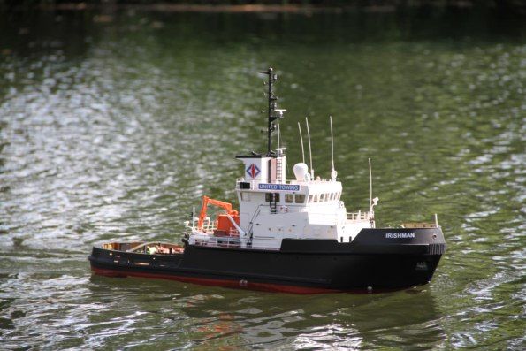
On the water
Handling on both models is broadly speaking identical, which is hardly a surprise either. Irishman (née Yorkshireman) has more modern motors, gearboxes and better propellers. Both new and old models are stable and can handle a fair bit of abuse in terms of sharp turns, stopping suddenly and going astern etc.
Conclusion
The first Yorkshireman kit was purchased for £149.95 on 6th December 1990. At the time it was Model Slipway’s initial offering and it was a quantum leap forward in standards of quality and value for money to what was then generally in the marketplace. This new revamped kit, first issued in 2010, further improves on that 1990 product, but the price is now £269.00. So over 20 years, an increase of 80%. Not bad at all I think if you compare that with prices of everything else we have purchased in the interim 20 year period.
So, a great kit at a very competitive price. Yorkshireman and Irishman were sister tugs, hence this new model of mine being named as the latter. It’s a nice size, internal access is good and it performs well, What more could you want?
Photo Credit: For the on the water pictures this goes to my good friend Neil Clark, to whom I now owe a bacon sandwich………


