Dr. MARCUS ROOKS converts the Doyusha kit to steam power
A bit of history….
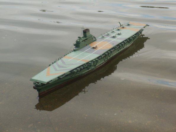
At 1057hrs on the 29th November 1944, the new Japanese aircraft carrier IJN Shinano then on her maiden voyage, capsized and sank near Cape Ushio off Japan’s coast after a torpedo attack. Thus, an undignified end to a very short operational career! Normally a disastrous maiden voyage would have put a ship into the history books but this was not to be and she remains today the least well known of the WW2 Japanese aircraft carriers.
Enjoy more Model Boats Magazine reading in the monthly magazine.
Click here to subscribe & save.
She was the end result of the disastrous action at Midway in 1942 when Japan lost four of its large fleet carriers. Although the situation was serious it was not desperate, but more aircraft carriers were required.
At that time, the third of the Yamato class battleships, IJN Shinano, was being constructed at Yokosuka Naval Yard, her keel having been laid in May 1940. In June 1942 the decision was made to convert her into an aircraft carrier and being based on the Yamato battleship design she would be the largest aircraft carrier so far constructed.
She was intended to be a support carrier with extensive repair facilities, but also having a complement of offensive aircraft. When finished she would tip the scales at a colossal 70000 tons and she was the largest aircraft carrier in the world until the USS Forrestal.
In November 1944 she was commissioned, however there were increasing concerns about her safety due to recent mainland attacks by American aircraft. So she was sent to the Naval Dockyard at Kure for final fitting out at the end of that month, but Captain Toshio Abe in command objected as the ship was not in a fit state to sail. Watertight doors had not been fitted; only four boilers were operational and the crew had not been properly trained. His objections were overruled and he set sail on 28th November escorted by three destroyers.
Almost immediately the aircraft carrier was spotted by the American submarine USS Archer-Fish, commanded by Commander Joseph F. Enright. There then ensued a cat and mouse game of pursuit and evasion as Shinano’s escorts had also spotted the submarine. The submarine tried unsuccessfully to get into a firing position on many occasions. However, due to the zig-zagging of the aircraft carrier and her reduced speed, USS Archer-Fish was able to maintain contact. At 0305hrs on 29th November, USS Archer-Fish submerged and 10 minutes later fired a spread of six shallow running torpedoes. Four struck home causing considerable damage, which at first was not thought to be fatal. However, very soon, due to the lack of watertight doors and poor crew training, the situation turned desperate. At 0745hrs she lost all power and was dead in the water and listing badly. Two of her escorts tried to take her in tow and an attempt to beach her on Cape Ushio was also abandoned. Finally at 1057hrs, 200km south east of Shingu, she capsized and sank, taking 1,400 sailors including the captain with her. So, a rather short military service life for the ship and an unnecessary loss of life.
Selection of kit
I had been thinking for some time of building another steam powered plastic kit based model, but knew that adequate internal height would be essential.1:350 scale battleships are big, but don’t have sufficient internal height for a steam plant so I began to think in terms of an aircraft carrier.
There are a number of aircraft carrier kits in 1:350 scale available. Tamiya’s enormous USS Enterprise would have been ideal, but I really was looking for something a bit more archaic. The Japanese carrier Akagi was beginning to look a distinct possibility, but as I was heading to Japan to meet the in-laws, I decided to visit my favourite model shop and see what was available.
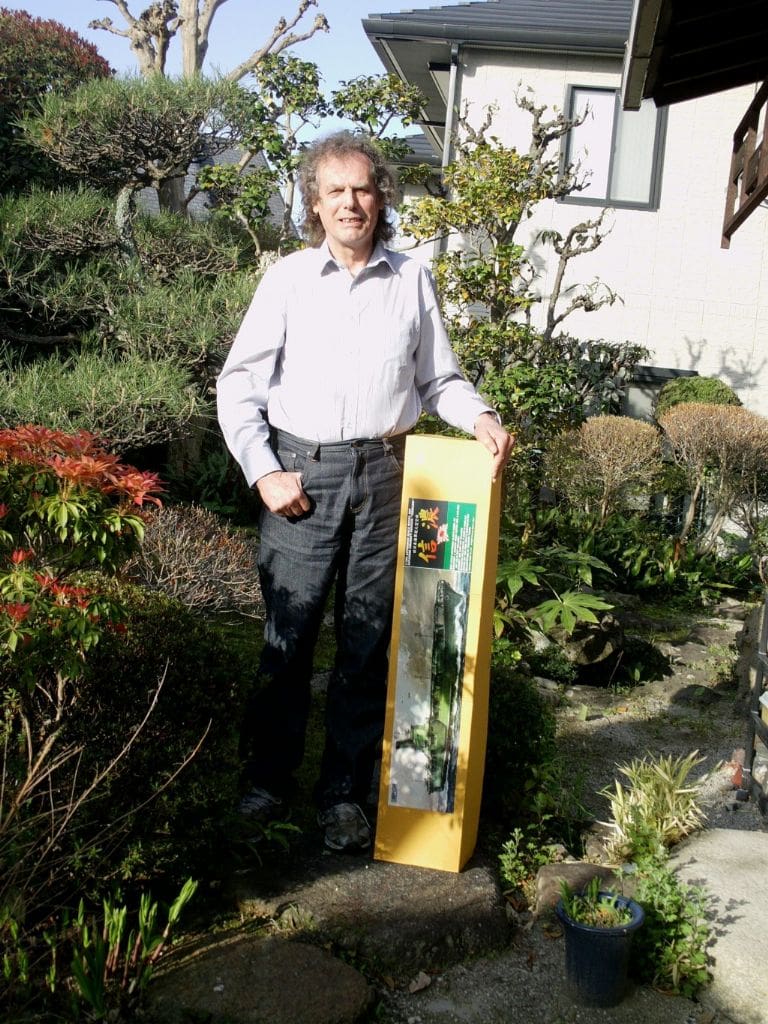
This is a peculiar sort of shop, called YodoBashi Camera and is in downtown Osaka. It is nominally an electrical store, but the top floor is dedicated to toys and games. What an Aladdin’s cave indeed, with hundreds of kits and more important, lots of large model ships, but unfortunately not an Akagi. However, my eyes did alight on another kit, a monstrous affair that would suit me even better. This was the Doyusha version of IJN Shinano. I was familiar with the name of Doyusha, but had never constructed one of their kits which cost 13000 yen (£93).
The kit is 1:250 scale and there is a similar sized IJN Musashi. The box was well over a metre long. I then wandered around the store, also buying paints, chains, degaussing cables and such like and also later bought the Tamiya cruiser, IJN Mikuma.
Things never go smoothly! The kit got lost on the way back from Japan, but after filling in numerous forms, it finally appeared on my doorstep.
What’s in the box?
As a plastic kit it is rather primitive. Considering the size of it, a lot of extra detail could have been incorporated and the fit of many parts was not good. The front section of the flight-deck was considerably warped, but fortunately I noticed this whilst still in Japan and the nice people at Doyusha sent a replacement before I left, so ‘well done’ to them! Having said that, over the years I have found that if a model is too fiddly then it will become damaged by the time I have finished modifying it, so it would suit my purpose very well.
It was not all that accurate either and the illustration on the box seemed to bear little resemblance to the kit. There was a note saying that there may be differences and indeed there were! However, a Tamiya IJN Musashi in 1/350 scale was of great help for studying the layout of propellers, rudder and the overall shape of the hull which was of course based on the Yamato design.
The thickness of some of the parts was quite extreme. The hull was nearly 3/16in. thick in some places, which allowed it to be drilled and tapped directly for screws.
Very quickly I realised that it was not made from the usual polystyrene as the usual glues did not seem to be that effective and the plastic seemed unduly tough. Normally it is quite easy to remove pieces from a sprue, but here it was necessary to remove them with a saw. A trawl through the internet gave the answer that it was made from ABS plastic similar to some sanitary waste fittings. The kit itself is intended for electric propulsion, quite decent shafts and propellers being included as well as a nicely manufactured gearbox.
Acrylonitrile Butadiene Styrene
Otherwise known as ABS, this substance, like Polystyrene, is based on styrene. It has a number of configurations depending on use, but high temperature moulding improves the gloss and heat resistance. It has a useful range of minus 25 to plus 60 degrees C and importantly a glass transition temperature of 100 degrees C and a melting point of 105 degrees C. Thus the critical temperatures are not that different from polystyrene, but unfortunately ABS is flammable when exposed to high temperatures, when it will boil and burst into intensely hot flames. This was not exactly what I wanted from a steam powered model boat hull!
ABS costs twice as much as polystyrene, but does have the advantage of superior gloss and toughness, and I can certainly vouch for the increased toughness! A trip to the local DIY shop procured some suitable solvent at what I thought to be an exorbitant price of £10, but I had no choice and consequently I felt as if I were a plumber when assembling the kit.
Steam plant
I intended to go the whole hog with this model by designing a conventional high pressure marine centre flue boiler with a simple gas burner. Perhaps the biggest leap forward was that I intended fitting a miniature steam turbine as by WW2 all major ships were propelled by these engines. Mine would be a simple impulse turbine with a housing made from aluminium with a steel rotor, divided in two on ball bearings with corresponding jets.
The biggest problem with a steam turbine is that the speed of rotation requires extensive gearing to reduce its speed and increase torque. I had no idea how fast or powerful the turbine would be, so I would have to carry out trials to see what sort of gearing would then be needed.
Running gear
Preliminary examination of the model was interesting. The kit provided proper propellers, shafts, gearbox and a rudder, but unfortunately they were a bit ‘toy like’, so some work would be required.
Construction begins
The instructions were what you may call minimalist, in fact virtually non-existent. The parts were not numbered, so you had to refer to a diagram of the various sprues to identify the various parts. This was fortunate(!) as anyway I had managed to lose the instructions! Consequently the bulk of construction was done using experience, general knowledge and information from a reference book. In the end I don’t think construction suffered very much because of the loss of the instructions.
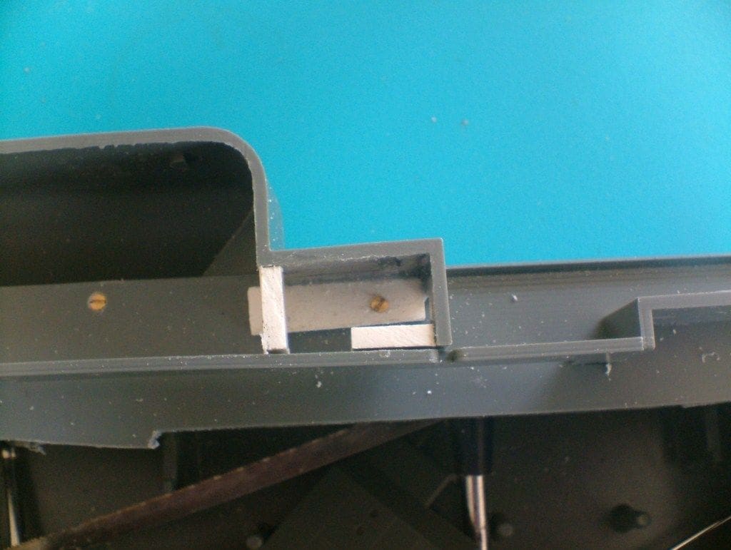
The hull was easy to locate in the box as it is so enormous. Numerous moulding lines had to be sanded away and the deck came in three sections attached by self-tapping screws. Not a bad idea in itself, except the screws were huge and stood proud of the deck. This was overcome by increasing the depth of the countersink, thus making sure the screw heads were below the level of the deck so that they could be filled prior to final painting.
Discrepancies in the deck to hull interfaces rapidly became apparent. These were corrected by judicious filing of the hull or the deck where necessary. It was particularly prominent in the foredeck area where the deck was nearly 1/8 inch longer than the hull and the opposite was true at the stern. Some extra deck retaining screws were needed to reduce the beam of the hull to match the deck. This was achieved by cementing lugs on the inside of the hull and then drilling through the deck into the lug and tapping 10BA.
Eventually a reasonable result was attained, but there was a lot more work to do before the deck sections could be permanently fixed in place. At the bows, the awful moulded deck railings were removed (as they were from the whole model), plus the capstans and the raised edges around the flight deck supports. The anchor chains were also sanded off and hawse pipes opened out to receive new chains.
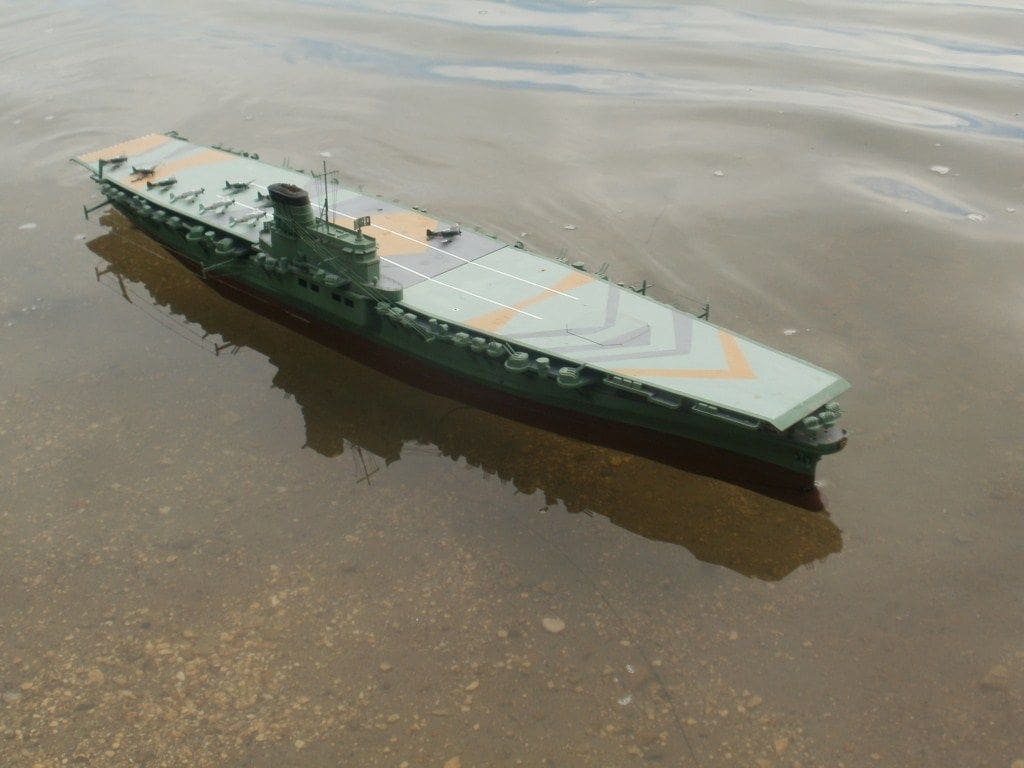
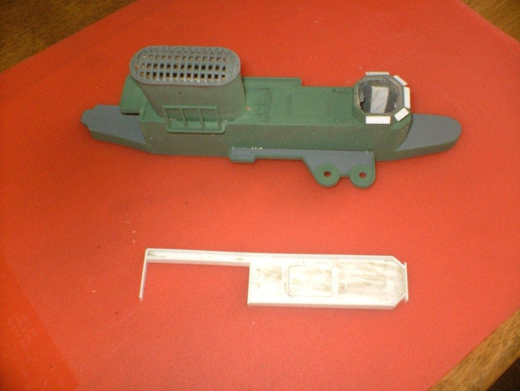
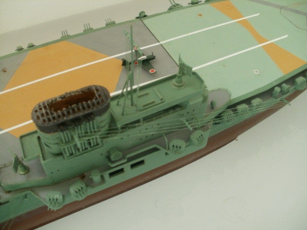
The island superstructure required considerable modification and even now I am not too sure about its accuracy. There is a lack of available information about this ship, which is only to be expected I suppose. The box art can be useful but also confusing as there are different representations depending on the manufacturer and scale. In the end, a mid-course was chosen, using a fair bit of modeller’s licence.
The island superstructure as supplied is totally wrong, so here are the major alterations. The fore and aft sections required complete re-contouring. The aft section face is stepped in the kit, but in full-size was flat. There was also a secondary armament position that is totally omitted in the kit. These alterations were carried out with polystyrene sheet, as were those elsewhere. The top is even more confusing as there appears to be an open area where there shouldn’t be and the radar is not on the mid-line.
The top section was cut away at the bottom of the windows, leaving the windows in place. The original top deck was pared so that it fitted within the confines of the island superstructure and cemented a little below the top edge. A new bridge was then fabricated that completed the front part of that section. A completely new deck was then cemented to the top of the bridge.
Flaps were glued over the windows as I assumed that they would have been lowered whilst in combat (also saving glazing). The front of the superstructure has two sets of windows and it seems that the lower set should just be slits, so these were modified accordingly.
The alterations show quite clearly in the photographs as they are white as opposed to the original grey ABS. All the alterations required a considerable amount of filling and sanding before a descent result was achieved.
Since the model was to be steam powered, not unreasonably the funnel would be used to exhaust the boiler fumes. I was intending to make a simple keel condenser so there would not be volumes of steam coming from the funnel. From experience with my plastic HMCS Snowberry, the plastic funnel cap should be strong enough to withstand the heat of the exhaust gases.
Due to the previous alterations, the funnel had to be extended by about 1/2 inch (13mm), which was tricky as it is at an angle to the island superstructure. In the end, the height was built up using layers of polystyrene sheet cemented to the base. When fully set these were sanded to the external profile and the lumen was drilled out to accommodate the boiler pipes.
Illustrations indicate that there were no steam pipes running up the inner side of the funnel and only its outer face. Presumably these were safety valve outlets for the boiler. All the existing pipework was sanded from the funnel and new pipes fabricated from 1/16 inch copper tube which looked much better.
This was done by drilling a series of nine holes in the funnel base and bending the copper tube to profile as shown. It was worthwhile making a little jig to get the bends identical as there are twelve of them.
An opening through the base had to be made to allow the tubes from the boiler to exit. At this point I had not decided on the final arrangement so this was left for later. The radar supports provided were extremely poor, so new ones were turned from brass using various photographs to determine their correct profiles.
Running gear
This always needs the most alterations to make functional, even if this model was designed to be motorised in the first place, but at least we had a gearbox, propshafts and a rudder as a starting point.
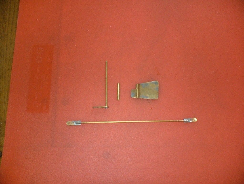
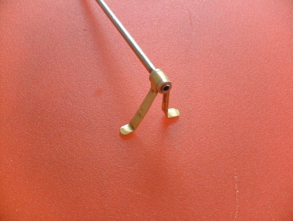
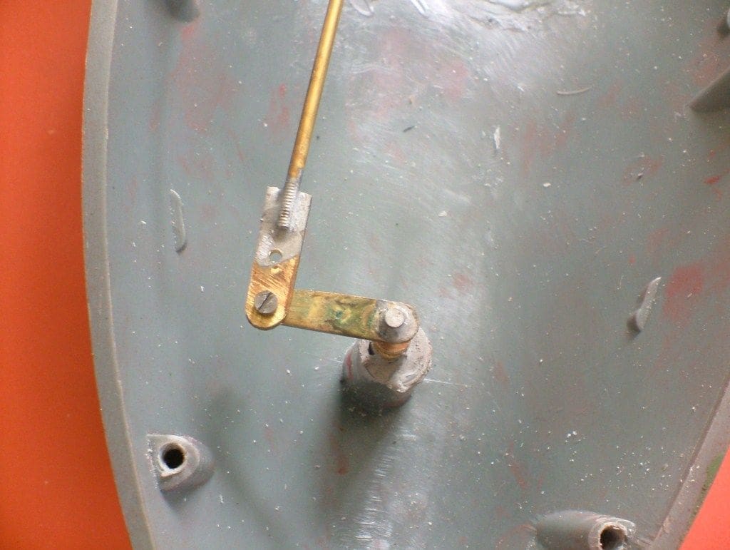
The original rudder was like a toy, so a new one was made from brass sheet. It is a balanced rudder which made construction a little tricky. First, a new rudder shaft was made from 3/32in brass rod and the blade cut from thin brass sheet. Two sections were profiled, press-fitted over the shaft and soldered together.
The rudder servo arm was cut from 1/16in brass sheet and later soldered to the top of the shaft. A rudder shaft bush was machined to suit and cemented into the hull. The rudder servo is supported on a platform made from polystyrene, positioned well away from the gearbox and steam plant.
The propellers supplied were nicely made, of fairly large diameter and seemed to have a reasonable pitch, so I decided to use them, although propellers for steam engines usually need more pitch and a larger diameter than for an equivalent electrically driven version.
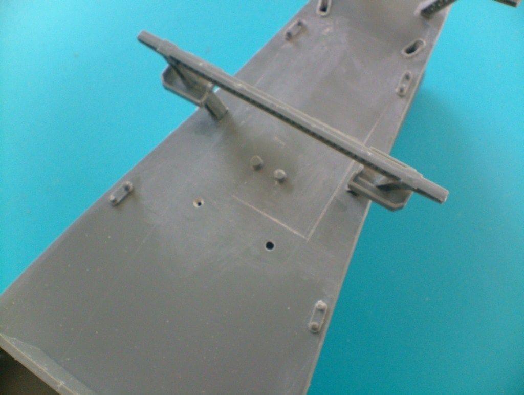
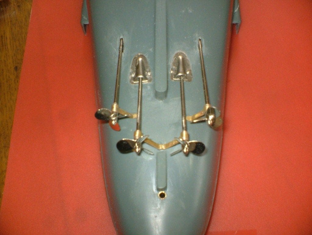
The propeller shafts exited at far too acute an angle from the hull. The Tamiya IJN Musashi (also Yamato class) has them virtually horizontal. So, out came the drill and the holes in the hull were drilled at a shallower angle penetrating the old gearbox supports. The gearbox would therefore have be repositioned lower and further forward in the hull.
The propeller tubes could now be inserted at a much more realistic angle, but it is not possible to get them completely horizontal as the propellers are quite large in diameter and have to clear the hull. No outer support brackets for the propshaft tubes are provided in the kit. These are functionally important on a model of this size, so had to be constructed.
The main body of each of the propshaft tube supports was machined from 3/16in brass rod with the central section reduced to about 5/32in to accommodate the support arms and drilled for the tubes. The support arms were made from 0.8 x 3.2mm (1/32 x 1/8in) brass strip. A suitable length was cut off and softened by heating to red heat and cooled. This was wrapped around the central boss and soft soldered in place. The bracket with the propshaft tube was then inserted into the hull and its arms bent and adjusted to give maximum support. Once all was in line, it was glued and screwed firmly in place and the procedure repeated for each other propshaft.
Inside the hull, are stuffing boxes filled with grease around the inner ends of the tubes. These didn’t work too well, so putty, sealant and glue was needed before a watertight result was obtained. The propshafts were joined to the gearbox by short lengths of electrical tubing, which was adequate for this model.
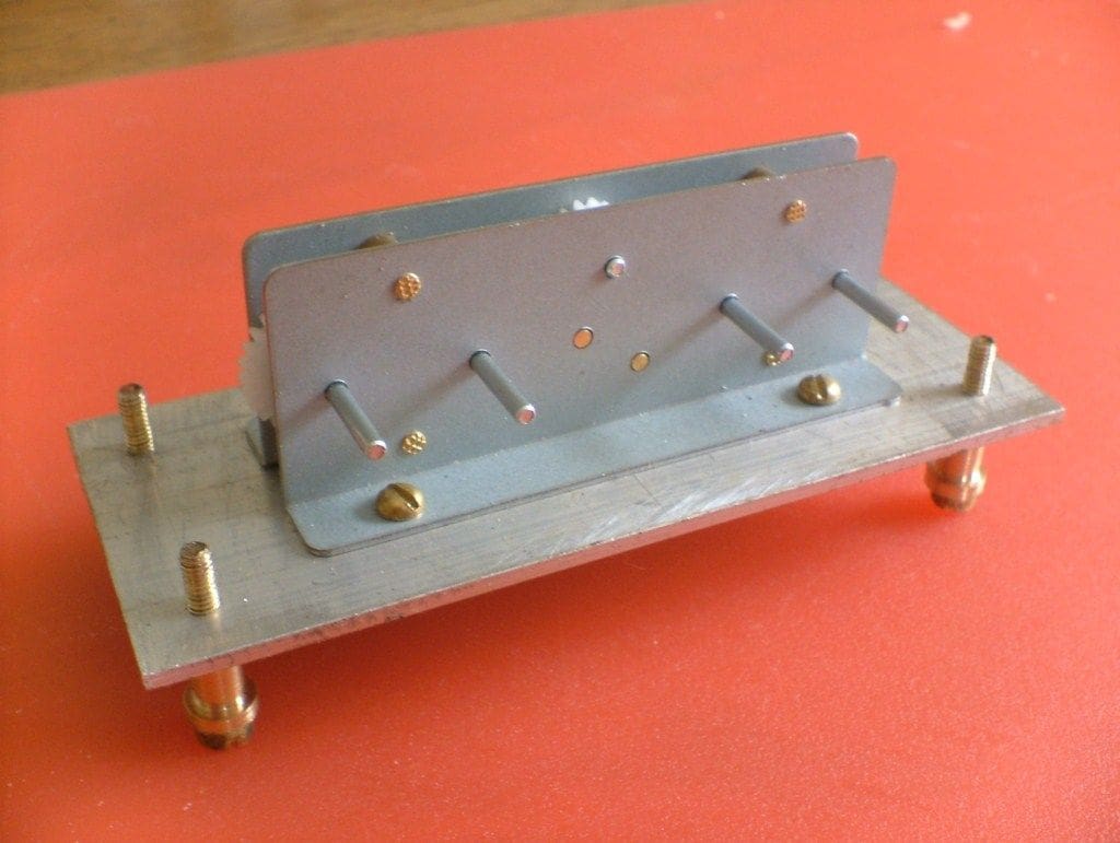
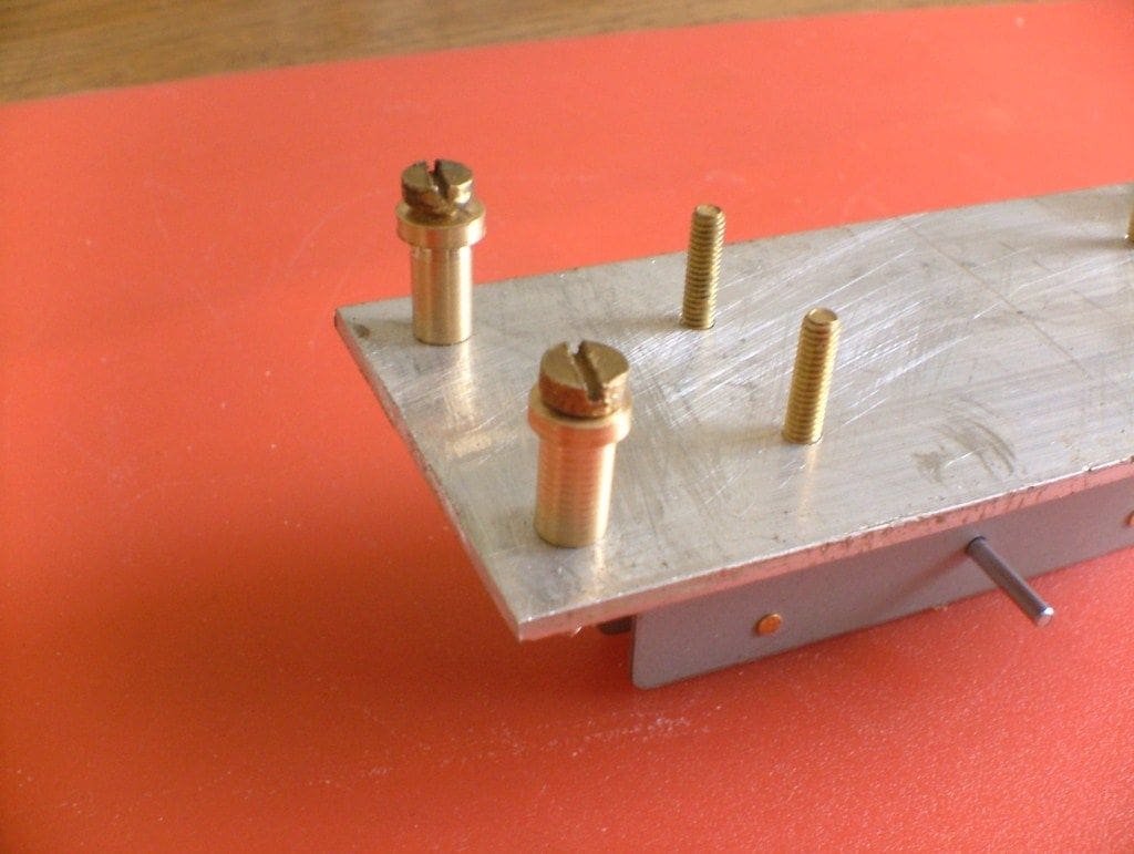
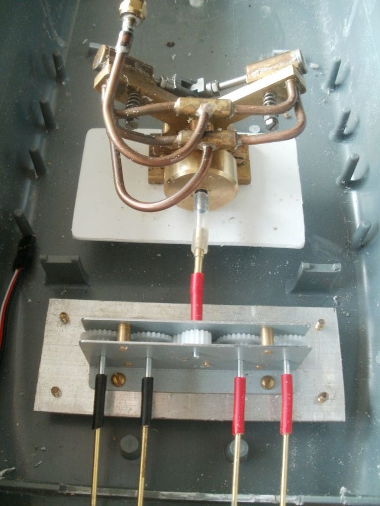
As designed the gearbox was far too close to the propeller shafts, causing the very steep angle, so it had to be moved further forward, amidships. Some of the existing internal plastic hull support pegs had to be shortened for the gearbox to sit sufficiently low in the hull. A new base plate for the gearbox was constructed from 1.6mm (1/16in) aluminium sheet to which the unit was attached with 6BA screws and four brass spacers were machined to support this plate. The gearbox assembly is held in place with 6BA screws inserted from the outside of the hull through the spacers into 6BA holes in the base plate. Okay, a bit ‘Heath Robinson’, but no one usually looks underneath a model hull and this meant the whole thing was very positively placed in the hull.
Steam turbine?
I intended to fit turbine drive to this model. To that end I had obtained a simple impulse turbine of 38mm (1.5ins) diameter. There were two rows of blades staggered to provide an even force. It was a lovely looking item, but there was a problem. It did not work very well and was certainly not powerful enough for this model.
On examination I found that the blades had been machined in the wrong plane so that the steam was not impacting them in the correct fashion. This is the current situation with the turbine, whilst I try to sort something out so it can later retro-fitted.
Tried and tested
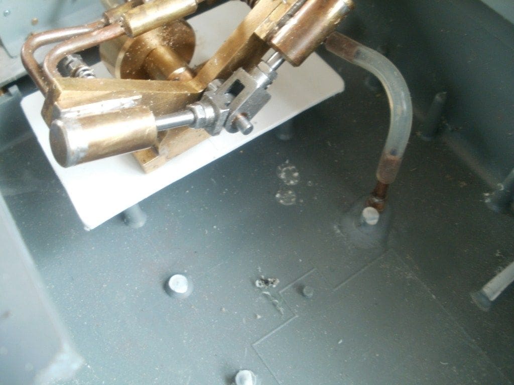
Time was pressing, so I reverted to an old tried and tested vee-twin oscillator, previously described in this magazine. I really did not want to revert to this, but discretion was the better part of valour. This engine is also attached to the hull with 6BA brass screws and connected to the gearbox input shaft by another length of tubing.
One problem with using steam engines for models is the exhaust steam. It may well look the part to have clouds of steam pouring from the funnel but this is far from full-size practice. All major steam powered vessels were fitted with condensers allowing the water to be re-used but even more important, they increased the efficiency of the engines.
A condenser does this by increasing the differential in the live and exhaust pressure; by creating a vacuum on the exhaust side it effectively increases the usable pressure on the piston.
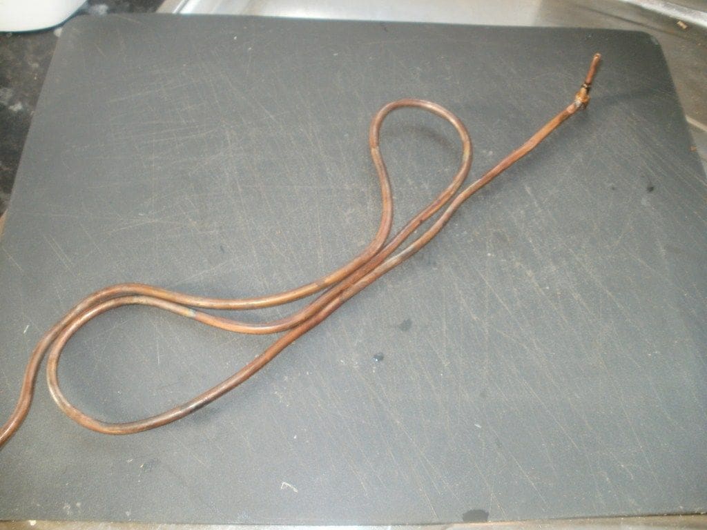
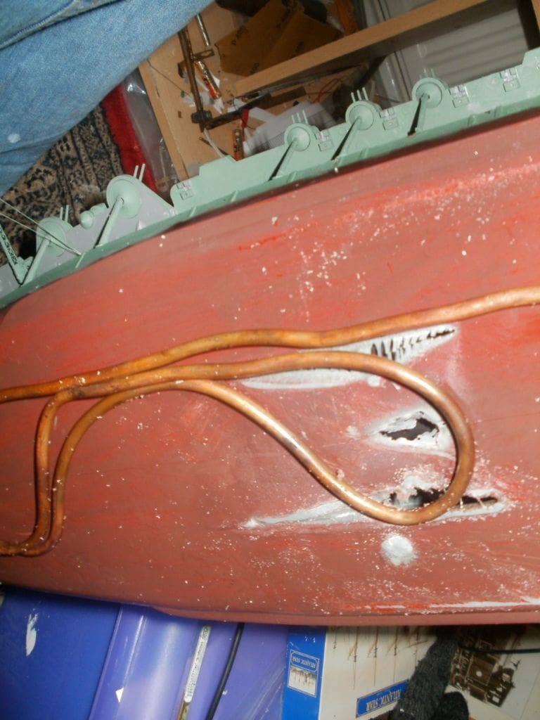
Surface condensers are quite complex items to make and not really justified with what is really just a toy engine in this case, but a keel condenser is another question. These are simple affairs, comprising a length of copper tubing attached to the outer hull and submerged. The exhaust steam is fed into the pipe and the surrounding water acts as a cooling agent, turning the steam to water. It is usually then collected in a vessel called a Hot-Well and re-used. A pump may be required to get the condensed water to the tank, but not in this model.
The Shinano model has a coil of 3/16in o.d. copper tubing attached to the bottom of the hull. Connections were machined from 3/8in brass hex rod which project into the hull. One end is connected via silicone tubing to the engine exhaust and the other leads up to a water tank in the bows, an extension taking the outlet from the pipe to just below the top of the tank.
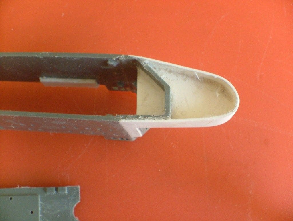
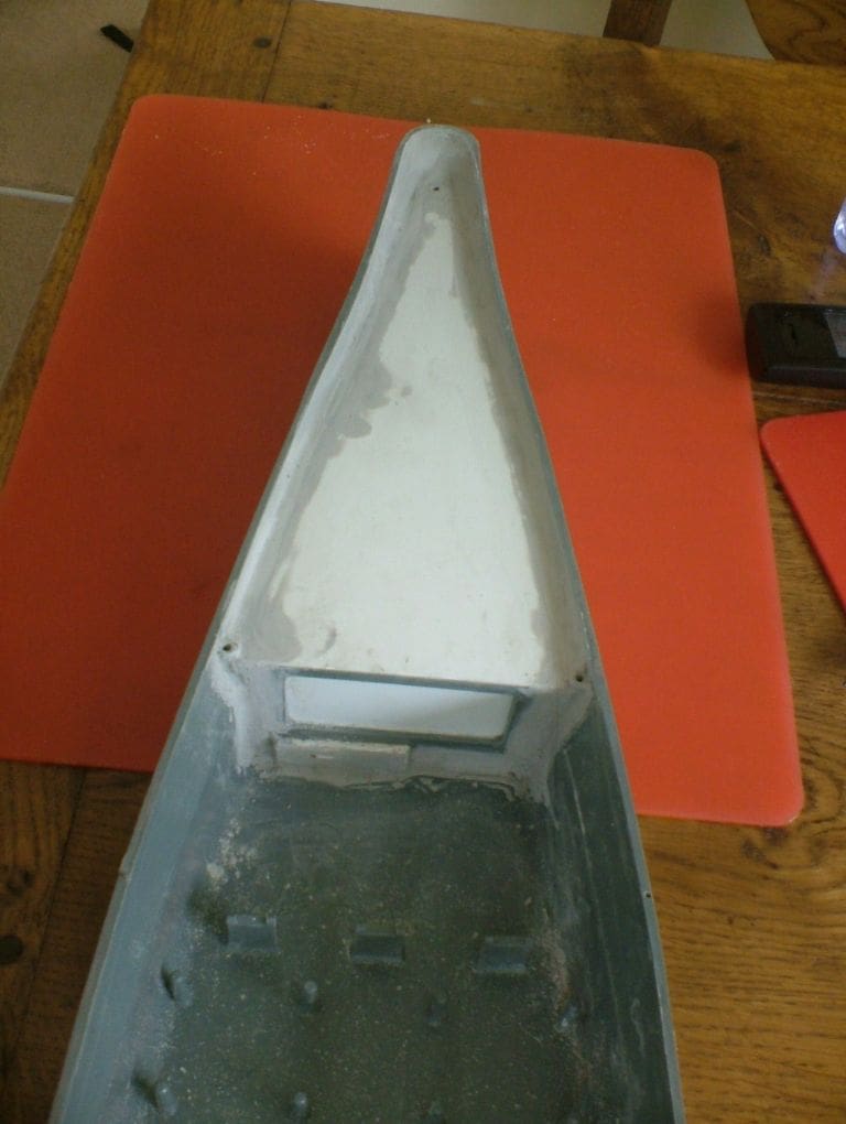
Condensing tank
To make the tank I started by utilising a redundant part from the kit as there was a rear bulkhead supporting the flight deck that wasn’t going to be used. It was cut down in height to below deck level and its central aperture was filled with sheet styrene. This bulkhead was then cemented in place about six inches from the bows. A tank top was cut out of styrene sheet and carefully adapted to the hull, but it has to fit around the bow attachment points for the flight deck, so careful drilling was required.
The top was cemented in place and made watertight with putty. The outlet/filler tube was next on the list, it just being a length of 3/8in copper tube with a mounting flange soft soldered in place. The position of this tube was quite important. The Musashi kit showed there was a large round object on the foredeck between the anchor chains and I decided to follow suit on Shinano. The deck was temporarily held in place using the various holding screws. A 3/8in hole was then drilled through the deck and into the tank top at the position shown. The deck was then removed and the holes cleaned up.
The tube was cemented in place and the joint strengthened using putty. Whilst the putty was still malleable, the deck was replaced over the tube to ensure that it was still in the right position and the whole thing then put aside to properly cure.
The cap was machined from brass and shaped to represent an anchor capstan. To empty the tank, a syringe with a piece of silicone tubing is used to suck the tank dry. There is also an overflow pipe from the Hot-Well, should it become too full. Because the plastic hull is normally in water when steaming, that should help keep the hull and its internal fittings cool– at least that’s the theory!
Boiler
My plan to use a marine type boiler was also now shelved at this stage. It would have been ideal for a turbine, but was not really necessary for an oscillator engine, so I simply modified the USE boiler fitted to HMCS Snowberry – a good example of recycling!. Cost does come into it when fitting out steam powered models and any savings are very welcome. I still could not decide whether or whether not to use solid fuel or a gas burner, so I plumped for solid fuel initially and time would tell if that should be changed.
The chief alterations to the boiler involved the smoke box area. I had to arrange for the hot gases to be ducted up the funnel which of course is on the side of the island superstructure and this was achieved by fabricating ducting out of tin plate. This is a large model boat with raised sides as befits an aircraft carrier, but it was still barely high enough to accommodate the boiler and the safety valve was too tall. To resolve this, 1/4in was cut off the safety valve boiler bush, thus lowering the safety valve. There were still plenty of threads left in the bush so safety was not compromised.
A Mamod rather than a USE safety valve was also installed. Okay, different threads, but careful work with a taper tap and the job was done. The valve now sat just below the deck with room to properly activate. If it activated, the internal hull volume would fill with steam, but at least it didn’t poke through the flight deck. (Note: Only alter safety valve arrangements on boilers if you know what you are doing and can properly test for safety – Editor)
One other alteration was to cut away a portion of the end plate allowing the placing of the burner tray without having to raise the boiler off its mountings. As the boiler location was fixed, the engine could be connected to it with rigid copper tubing which is far more satisfactory than a flexible silicone pipe.
Testing
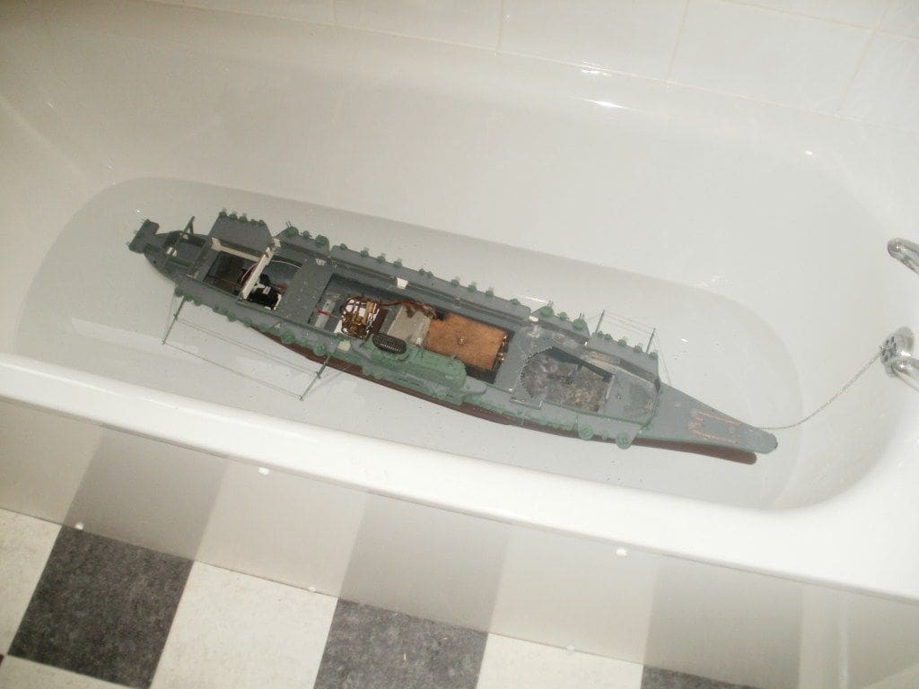
Bath test:
This would hopefully iron out any problems such as:
Are the propellers going in the right direction?
Would the engine be able to produce enough power to drive the gearbox and four propellers?
Would the model float?
Was the model going to be stable?
Well, it floated as I expected, listing slightly towards the island superstructure side and high in the water. The list was corrected and what felt like a ton of lead ballast was added to the hull. I had not made any calculations about the model displacement, but suffice to say that I did not think I would ever have enough ballast to sink the model to its correct waterline.
Firing up was surprisingly easy with a Mamod burner tray and solid fuel tablets. By pre-filling the boiler with hot water, steam was raised in a few minutes. The steam plant seemed to be working well and the hot combustion gases discharged nicely up the funnel. There was then a timely reminder about the amount of heat generated when the plastic funnel cap melted!
The exhaust steam was directed via the condenser unit to the Hot Well in the bows which seemed to be working quite efficiently. As planned, this bow tank filled with condensate that could be drained (by sucking out through the dummy capstan filler) after each steaming. The engine itself went like the clappers, but initially did not have sufficient power to drive the four propellers. So, the port and starboard outer propellers were disconnected to reduce the load. However, after several subsequent ‘running in’ sessions, particularly of the gearbox, the engine was able to drive all four propellers.
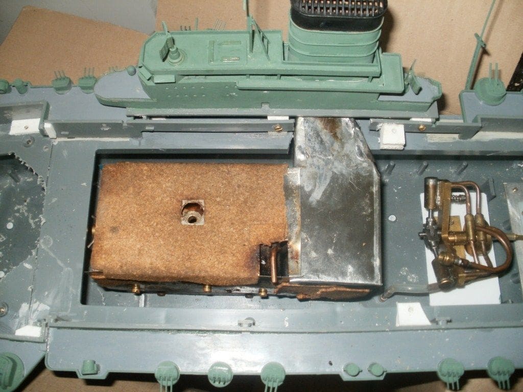
The flywheel then worked loose and things got worse. I had been testing the boat out of the water to photograph the rudder and propellers when to my absolute horror I realized that the boiler had melted the hull bottom. As the model was not in the water, it lacked the necessary external cooling effect and the plastic underneath the engine had overheated and melted.
So back to the workshop. The only remedy was to cut out the offending area and cement on a false bottom using polystyrene sheet. The inside was lined with a sheet of thin brass to spread the boiler load and any excess heat. Now, as long as the model is in the water there are no problems, but be warned!
There was an unexpected benefit from this disaster in that the boiler now rested about 3/16ins lower in the hull giving more clearance above it, so the safety valve bush modifications were now redundant.
Finishing off
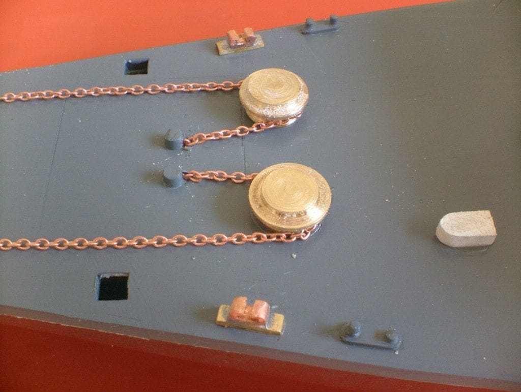
Attention now turned to the fittings. The foredeck had a number of fittings that needed remaking or were simply not there at all. You may remember that the capstans had been sanded off in the early stages of the build. New versions were turned from brass bar and fixed in place. Brass chain was substituted for the pathetic attempt of the original moulded links. The anchors are a peculiar design to say the least, and as one fellow modeller remarked, they look as if they would be more suited to Captain Nemo’s Nautilus.
There were no fairleads, so these were fabricated from scrap brass and copper. It is easy to reshape copper tube by heating and cooling. I thought that in the end they were over-scale so I spent some time flattening and generally slimming them down. Four were made, of which two were fitted at the bows and two at the stern. Some extra bollards were needed for the stern as well.
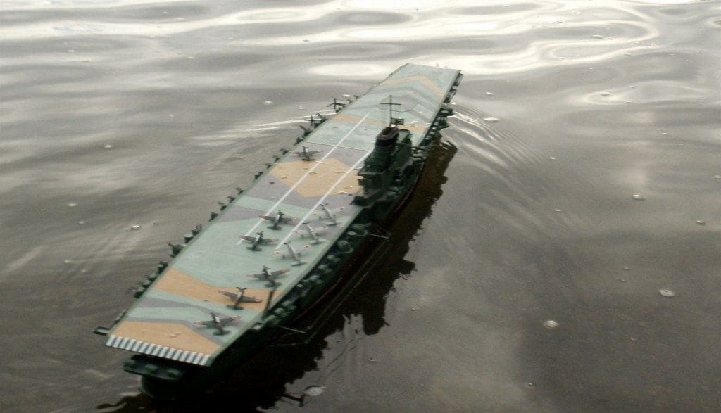
Then, and only then, could the deck can be screwed down. This is quite a difficult task owing to the sheer length of it all, but first the superstructure island was cemented in place on the flight deck. This could then be attached, but it still had considerable warping, so the retaining screws were relocated to where they were needed. Supports were cemented to the hull interior and holes drilled through the deck. The original self-tapping screws were reused and any redundant holes filled with putty and painted. The flight deck has to be removable to gain access to the steam plant for maintenance. The heads of the retaining screws were painted according to the camouflage so are not noticeable. Some ‘Toms Model Works’ etched railings added a little detail to the island superstructure.
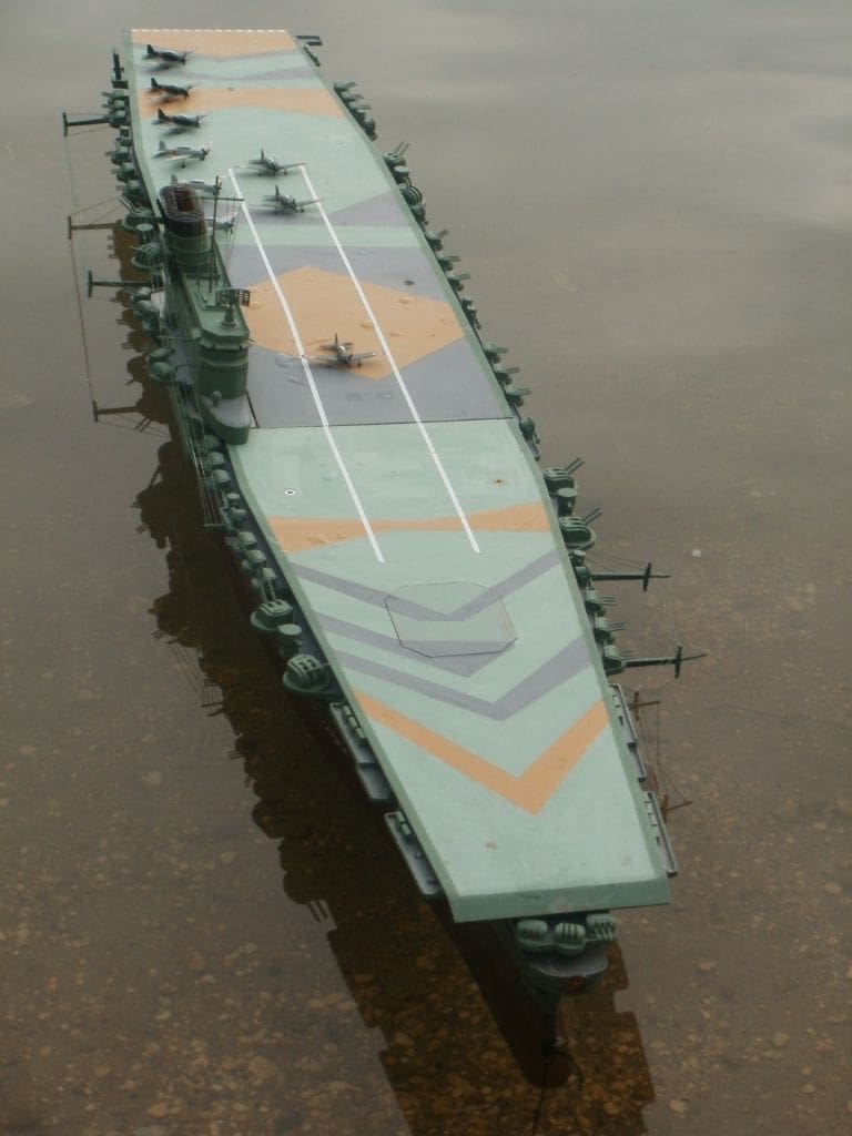
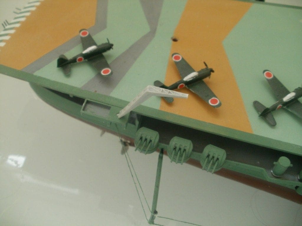
The final task was to construct the air group. The deck is enormous and the aeroplanes supplied are dwarfed by it all. IJN Shinano did have a small attack group, but was primarily intended to be a fleet support carrier providing repair and storage facilities for aeroplanes from other carriers. The scale of the model precluded using commercially available aeroplanes, so unless I can get my hands on any more, that’s it!
They were easy to construct as they did not have much detail, apart from the wheel struts which were the very devil to get to remain in position. They were painted in what I thought were appropriate colours.
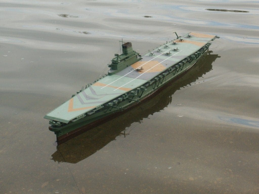
The hull was finished in White Ensign Models Camouflage Green. Apparently the captain of the attacking submarine USS Archer-Fish at first thought IJN Shinano was an oil tanker, so camouflage is effective!
The flight deck was a bit of a problem as there seemed to be no clearly defined paint scheme for it. The book on Yamato style battleships showed either a grey or a camouflage green pattern. In the end I went for the dazzle scheme shown in the book, mainly to use up old tins of paint.
On the water
When at last she was put in the water she handled quite well for such a large model. Speed was fine and not excessive, but more than enough to give adequate steerage. It was hard to tell that she was a steamer as the exhaust steam was condensed and there weren’t the usual clouds of steam coming from the funnel. However, despite the relative success of this model, I have decided that this will be my last plastic-hulled boat to use steam propulsion, as it is just too much trouble. The serious problem of the likelihood of melting the plastic hull is one that is hard to overcome, but it can be done if you have the passion for it, as hopefully my models have shown.