Kim White’s first model boat
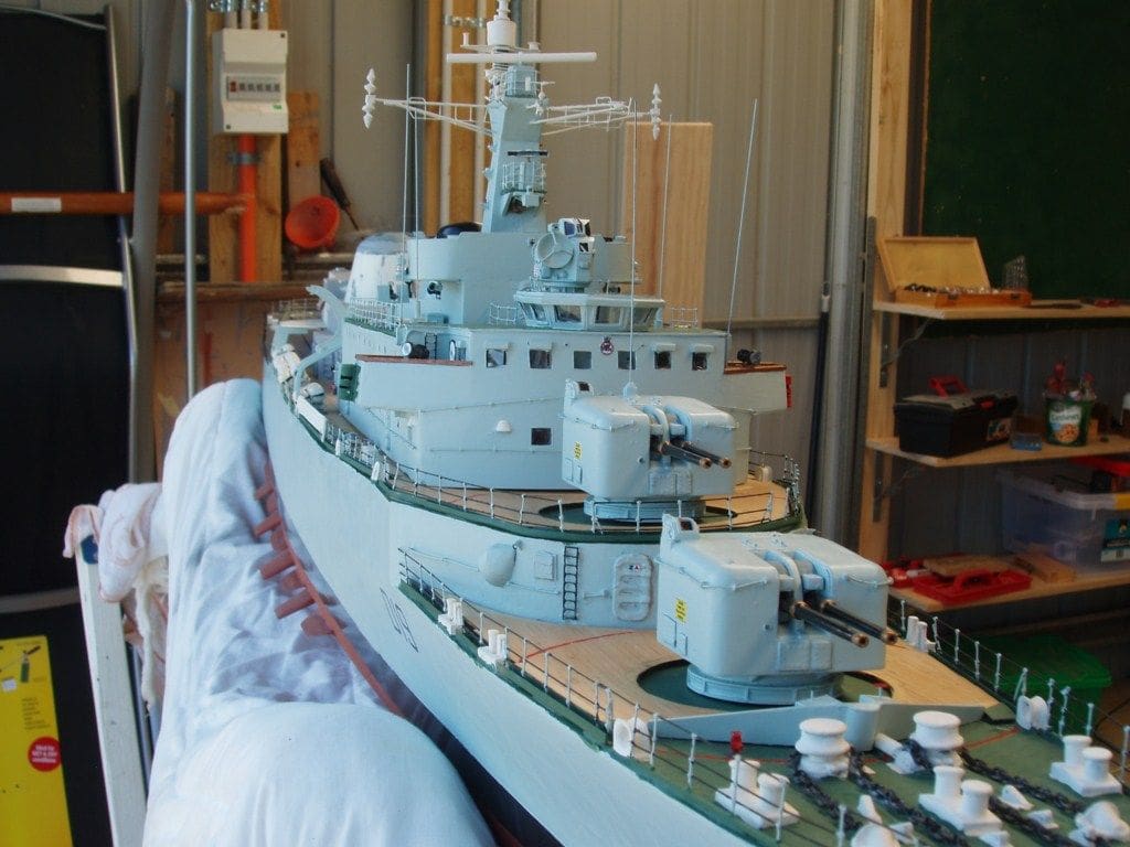
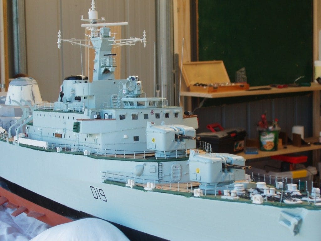
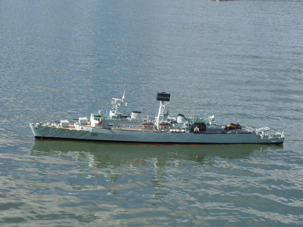
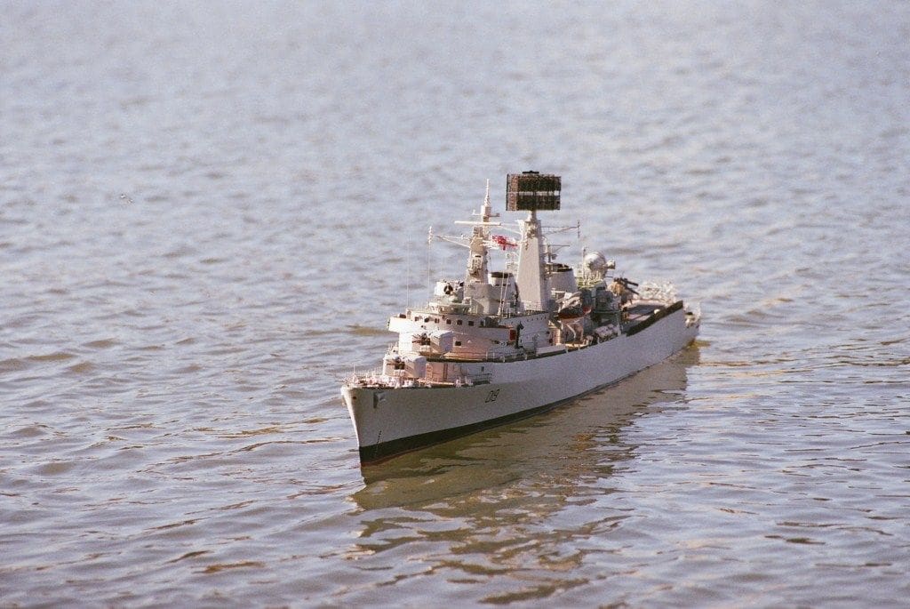
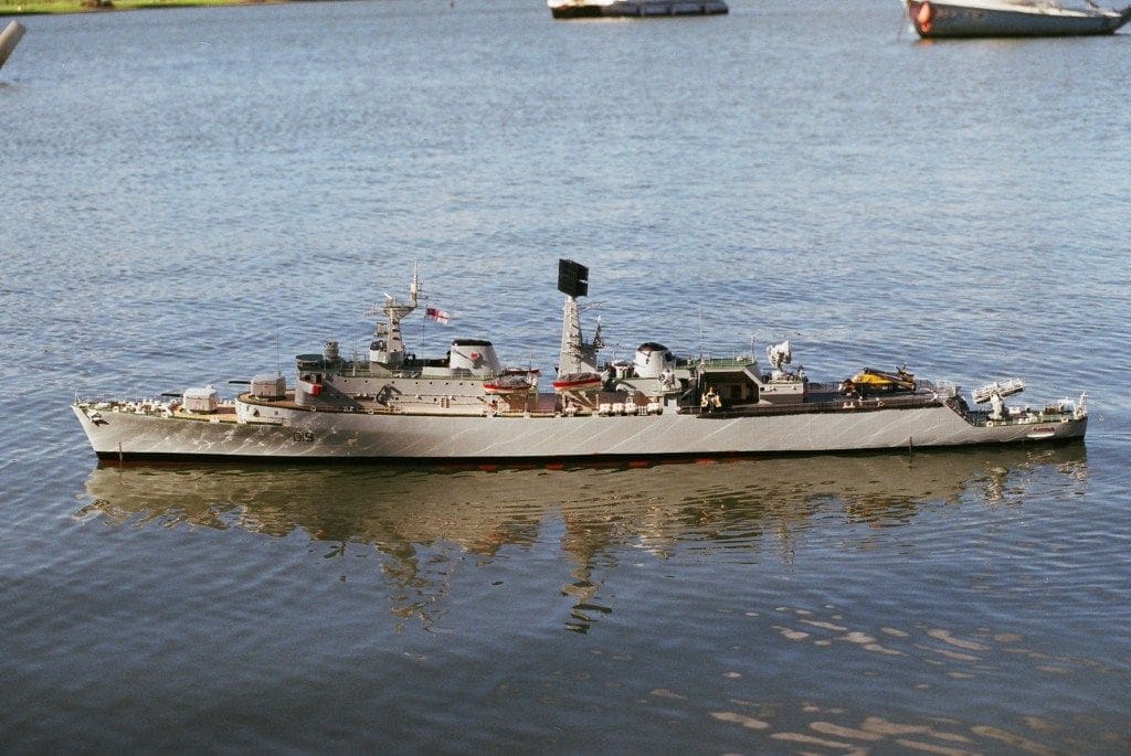
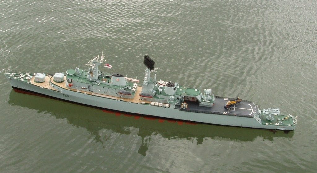
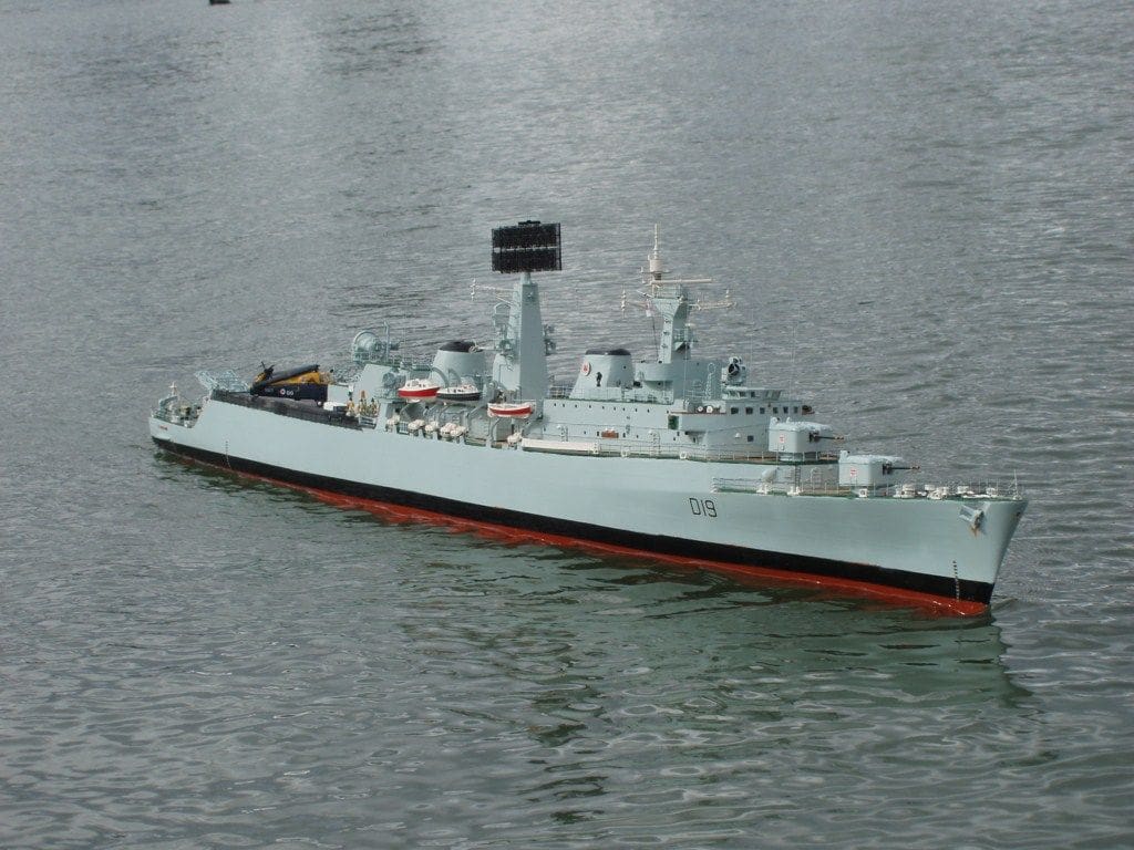
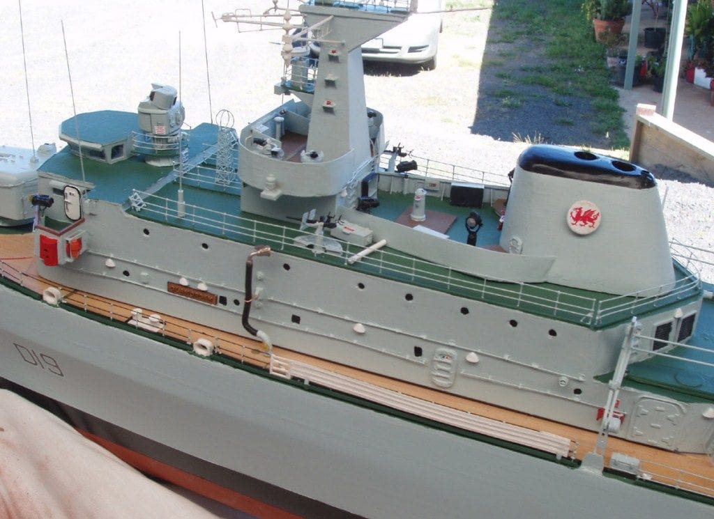
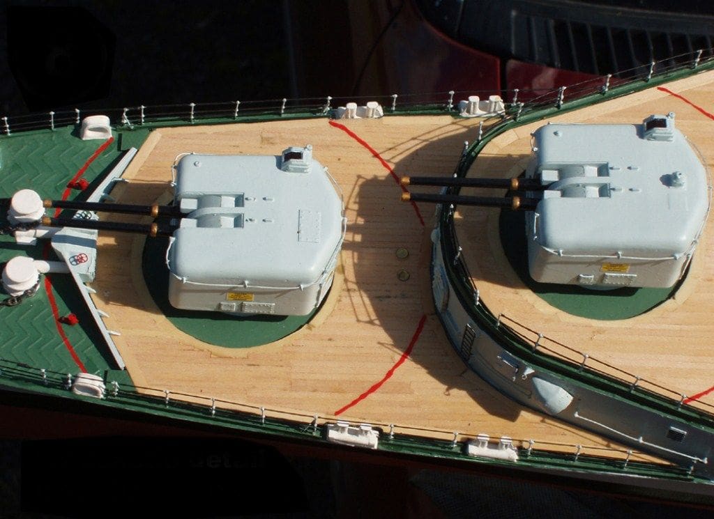
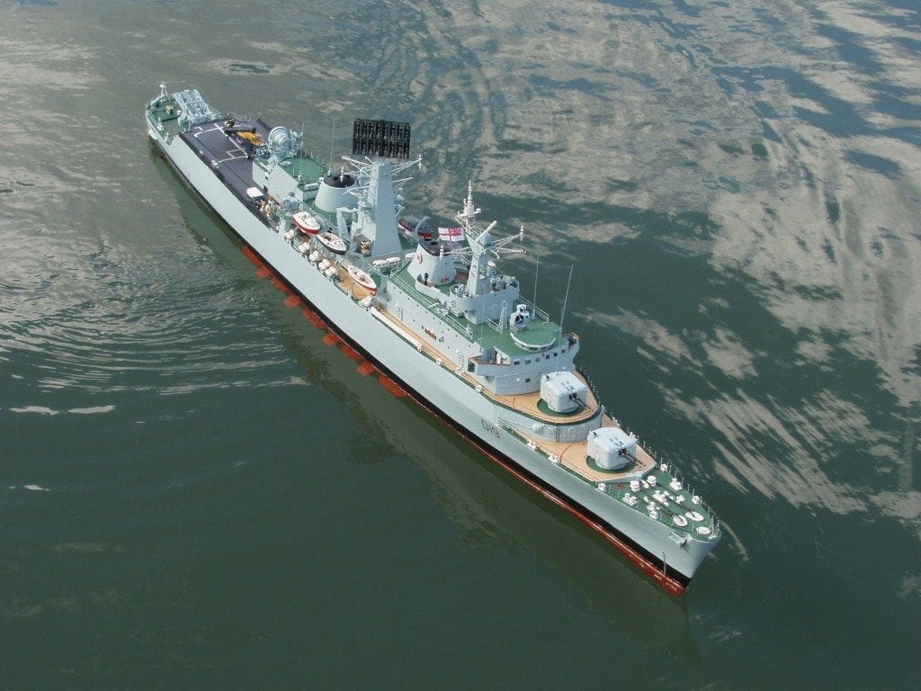
The subject of this article is a model of the County class Royal Navy DDG that was first commissioned in 1966. The eight ships of the class were the first RN vessels with gas turbines for speed plus a steam plant for cruising and the first with a missile armament, namely the Sea Slug surface-to-air missile and the Sea Cat point-defence missile. They also mounted two dual 4.5 inch gun turrets plus a Wessex HAS-1 helicopter with dipping sonar and were the first RN ships with an analogue computer to assist with target acquisition and fire control for the guns and missiles. They were 520ft long and displaced approx. 6200 tons and there was some debate as to whether they should be classified as cruisers.
I fell in love with these ships in 1981 when I was in the UK and was invited to lunch on board HMS Kent. I was struck by the sheer beauty of the overall design, and believe these are the most attractive warships designed for the Royal Navy since 1945. I was originally determined to build a model of HMS Kent, but never got around to doing anything until 2008 when I joined a model boat club in Australia called Task Force 72, which specialises in 1:72 scale warships. When commencing my research I met on the Internet, Commander Ian Inskip RN who was the navigating officer on HMS Glamorgan during the 1982 Falklands War and he in turn introduced me to a number of his ex-shipmates. This group of men selflessly assisted me with so much information on these vessels that in all conscience I decided I’d better build HMS Glamorgan instead! Over the next few years I was able to access this human database by email, asking questions like: ‘What is that square thingy I have arrowed in the attached photo and what does it do?’ and I would get back detailed replies, often with more photos, explaining what was what. So, a big THANK YOU to all these wonderful guys.
Enjoy more Model Boats Magazine reading in the monthly magazine.
Click here to subscribe & save.
As it so happened, HMS Glamorgan was a great choice of ship to model and I have chosen to build her as first commissioned in 1966, but she was in service with the Royal Navy until 1986, having survived being hit by an Exocet missile during the Falklands War. She later served with the Chilean Navy until 1998, finally sinking at sea in 2005 whilst under tow to a ship breakers. So she had nearly 40 years of useful and distinguished service.
The basics
An excellent GRP hull was purchased from Allan Pew who runs APS Models in Australia. At 1:72 scale, the hull measures 88 inches long and is just able to fit into my Toyota station wagon. Allan has already produced quite a few post-WW2 RN ships and he also produces other fittings such as 4.5 inch turrets, Sea Cat launchers, watertight doors, gun and missile directors and ship’s boats, all pre-cast in resin at 1:72 scale.
Many of the photo etched items such as the ship’s ladders and stairs were sourced from model railway supply shops as 00 Gauge is not that far different from 1:72 scale. John R. Haynes Fine Ship Models, Robin Carpenter of Scale Warship and Fleetscale also provided other brass photo etched parts such as asymmetric RN-pattern stanchions to make up the railings, davits, the huge double-bedstead 965 radar and 20mm Oerlikon guns, which were super models in their own right.
I make no apologies for not scratch building everything as this was my first ship model, but there was still a huge amount of gear to make, including the horrendously complicated 901 Radar Director and the equally difficult Sea Slug launcher. Also, some of the readymade items needed super-detailing to get them looking just right.
My thoughts about models
From my many years of absorbing knowledge from this magazine, I have formed the opinion that some otherwise brilliant models constructed by very gifted modellers were in the end sometimes spoilt by two things. Usually over-scale fittings and over-finishing of the paintwork and I was determined with HMS Glamorgan to avoid these perceived sins as far as possible.
For example: By over-scale I mean that you see a great model, but the builder has used such thick wire on the ship’s railings that were you on the ship, it would look like three inch iron bars, or commercial plastic ladders have been used instead of much-thinner brass photo-etched versions.
Over-finishing is where the finish is so uniform and perfect, the detail is not highlighted and it becomes less of a feature.
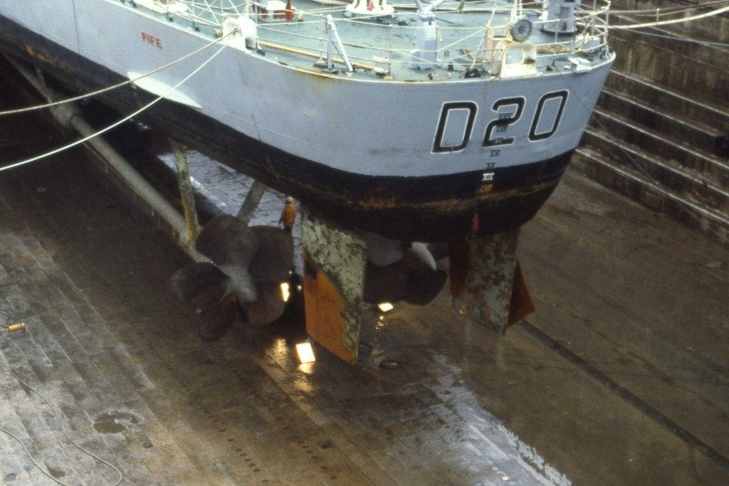
I firmly believe that models should reflect the full-size article in spirit as well as detail. Real ships have imperfections including patchy paintwork and imperfect dented hulls and these need to be highlighted if possible. Photo 1 is of the stern of HMS Fife D20 in dry dock and demonstrates very well a weathered hull and what I am trying to convey. Letting small imperfections stay is no bad thing and the model can be painted with a brush, perhaps with slightly varying shades of grey. Finally, I would borrow a trick from dioramas and use thin black colour washes to create shadows in the corners of superstructures, dirty-up the decks and outline WT doors and other objects with thin black lines to artificially create an exaggerated 3D effect. As I hope you will see from the model photos, I think it has worked with this model.
Hull
The GRP hull came with two sections of main deck, also made in reinforced GRP and the forecastle deck complete with a moulded herring-bone anti-slip surface plus the stern Sea Slug launcher deck.
After gluing 12mm Oregon stringers in place along the inside edges of the hull the fore and aft decks were fixed in place with glassfibre resin. A small cut-away section was made in the aft deck, so as to easily install the rudders a bit later. Deck edge stringers were then fitted to support the main continuous deck that becomes the flight deck at its after end.
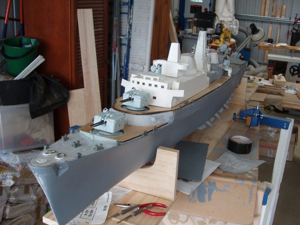
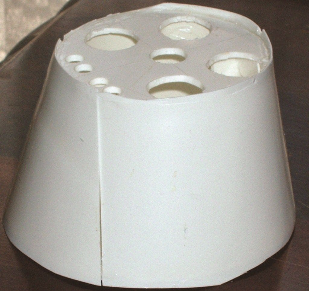
The next step was to fabricate the bilge keels and stabilisers from 1mm brass strip, which wasn’t easy. There are not just one, but four stabilisers and five sections of bilge keel per side. Each individual piece had tabs to locate it and through slits cut through the hull, each section was offered up and the tabs bent over inside the hull. These were then all fixed in place with reinforced glassfibre resin and when fully set, the inside of that hull area was also liberally coated with silicone sealant just to be on the safe side. Photo 2 is of the hull a bit further down the construction line, but it shows the five sections of bilge keel and four stabilisers. These were a key feature of the County class and cannot be ignored.
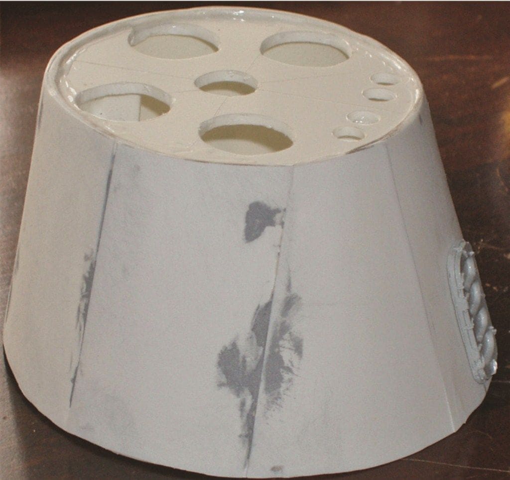
The GRP hull had one fault as it was just too perfect, being absolutely smooth! Anyone looking at a real RN ship from the 1950’s onwards will see how the hull plating is dimpled against the frames through the welding process. So a smooth hull looked wrong and I was not having it! After a few experiments I had a brainwave.
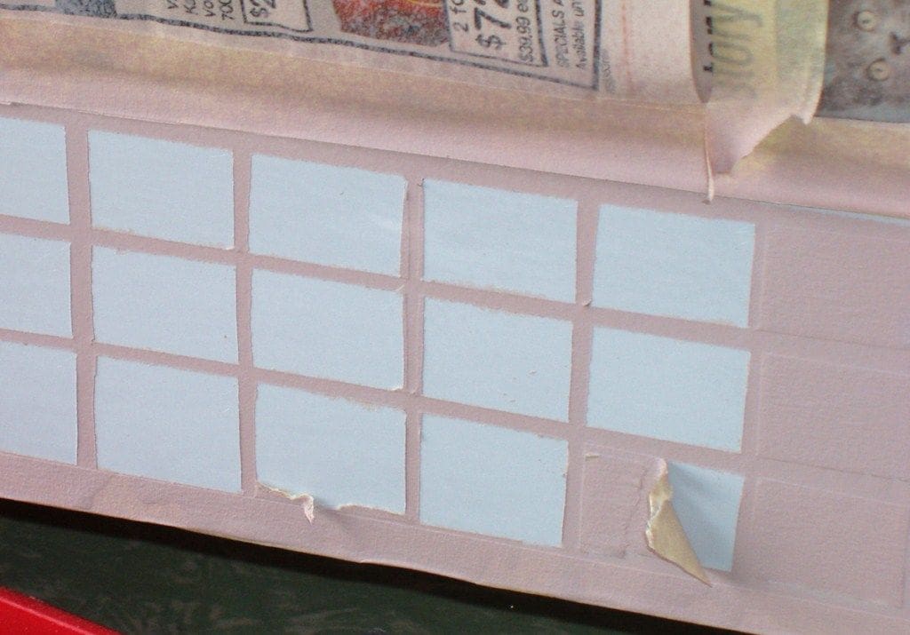
The hull was covered with a pattern of small rectangles of masking tape, leaving a small line of the hull surface between each rectangle to represent where the ship’s frames would be. An aerosol of pink automobile filler putty was purchased and sprayed over the hull.
The many rectangles of masking tape were then removed, leaving a grid of raised putty lines on the hull. A gentle sand over the whole thing made the clear-cut lines of putty far less defined and Photos 3 and 4 show the process. Okay, maybe not perfect, but good enough for me. The dishing effect is virtually unnoticeable from face-on in full sunlight, but becomes much more obvious with side-lighting which was the purpose of the exercise.
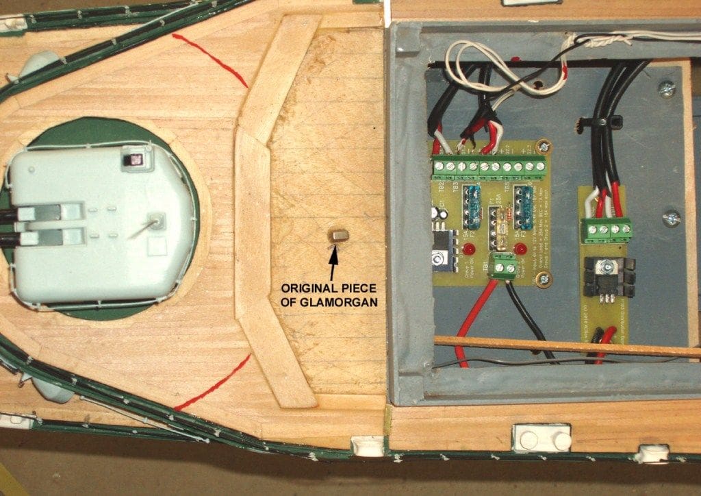
The depth markings and the ship’s name on the stern are photo etched or of plastic. Applying these required a steady hand with the superglue. Painting of the hull after the running gear was installed was by a brush so as to avoid an over-finished look. Also, a shard of the propeller smashed on an uncharted rock in 1981 from HMS Glamorgan was glued to the planked deck of the finished model for sentimental reasons, Photo 5. This last picture also shows some of the ACTion R/C Electronics components.
The right tools for the job?
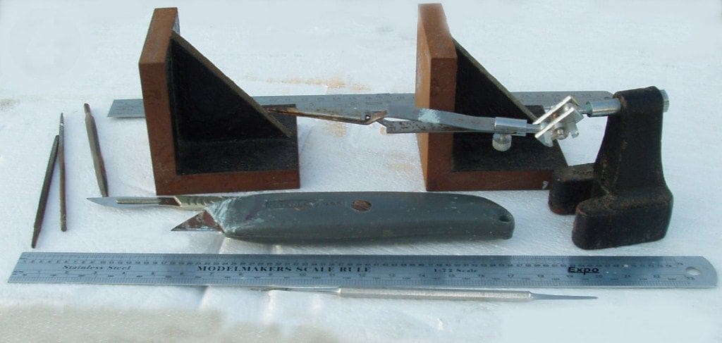
Despite my inexperience, I found that working with styrene was easy as long as I had the right tools and Photo 6 shows the most useful. There are steel rulers, one of which is a special 1:72 scale ruler to measure scale items in feet and inches); a Stanley knife and a real surgical stainless steel scalpel; a little ‘third hand’ tool that holds a set of hands-free tweezers (get at least two); some small files; a set of dentist’s picks (useful for poking holes in things and scribing plastic sheet to snap it along predetermined lines) and a pair of right-angle blocks to hold plastic sheets at perfect 90 degree angles for gluing. These are from eBay and were very cheap.
Not shown in the photo is a Dremel variable-speed multi-tool and a big box of drill bits, sanding and grinding disks plus routers. While on the topic of tools, one of the most important rules to apply is: Measure twice and cut once, but in truth, probably measuring three or four times before cutting might be even wiser!
Basic superstructure
The basic units were built with HIP (High Impact Polystyrene) that was purchased from an industrial supplier at a very low cost. It was possible to buy sheets of about 100 x 200cm for about $25A (£16) each and thicknesses of 0.5mm, 1mm and 2mm were used on this model.
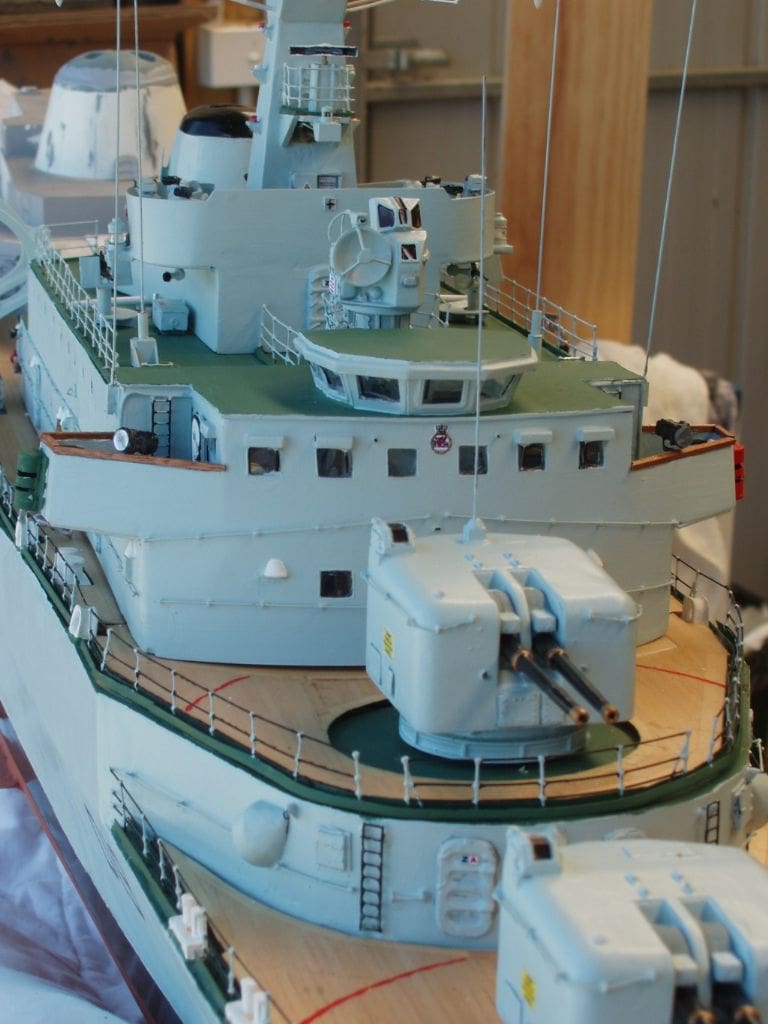
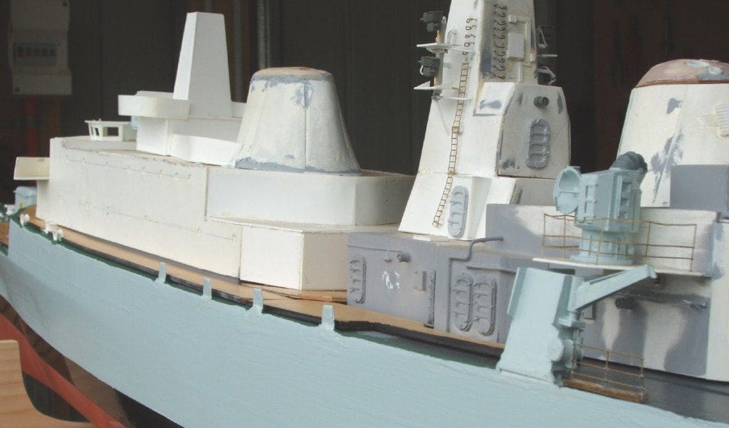
The complete superstructure units were actually a series of smaller boxes attached to large base units and I found it useful to picture the model as a series of mini-models on each of which I would concentrate to the exclusion of everything else and Photo 7 shows the superstructure under construction. To be honest, this was all quite straightforward measuring, cutting, gluing and filling and Dave Wooley in his Fleetscale HMS Daring project within Range Finder has described many of the processes very admirably. However there are a number of features worth highlighting.
Funnels
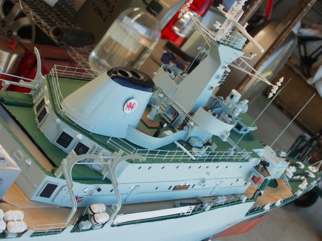
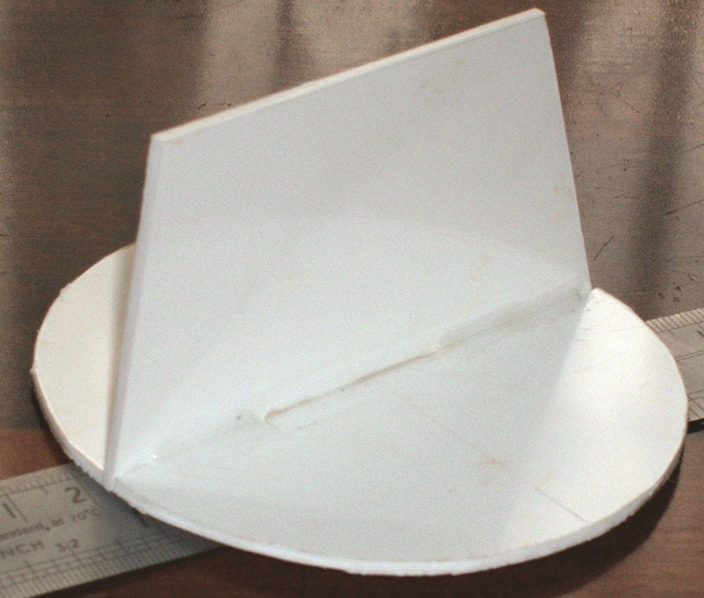
I have seen whole articles devoted to making these and some seem to be in awe of them, but those for this model were made in one day and quite easily. A silhouette of the basic shape was made and wrapped in 0.5mm plastic sheet to obtain the basic rounded shape and trimmed top and bottom. This form was then plated with more 0.5mm plastic sheet to build up the thickness and to show the plating visible on the real thing. Finally a carved a funnel cap from balsa, using the Dremel tool, finished it off. The same technique was used for both funnels, although they are vastly different profiles. Both have small wavy imperfections and wrinkles which mimic the real versions and Photos 8, 9, 10 and 11 show the four stages of the process.
Deck railings and portholes
Much thought was given to these which can let down many a good model by being over-scale.
Railings
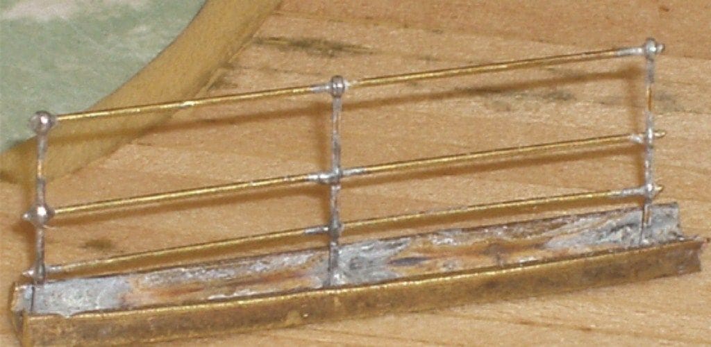
For making these, some modellers use panel pins and wire (or plastic) and when you see them they can look very heavy and thick. I was aiming for what you see when looking at photos of a real ship and actually that is almost nothing from a distance. Salvation came in the form of photo-etch stanchions manufactured by John Haynes, each threaded with 0.5mm brass rod, but a different method from normal of mounting them has been used.
The rails were pre-assembled and the stanchion bases soldered into either 3mm brass U-channel (where the railing goes against the spurn-water at the edge of the wooden decks), Photo 12, or if the rails were on steel decks or the edges of the superstructure roofs, 2mm square-section brass rod was used instead. Once complete the sections could each be painted away from the model, put aside until it was almost complete and then glued in place with small dabs of superglue. Should, in the future any of the railings be damaged, it will be an easy task to simply snap off the lightly glued-on section with needle-nose pliers and either repair it off the model, or replace it with a new section.
Portholes
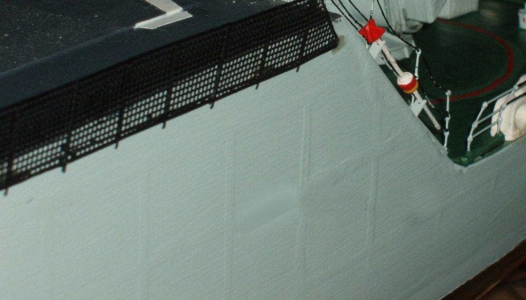
These can be made in many ways, but beware of them appearing over-scale. On HMS Glamorgan there were only portholes in the main superstructure units. On this model, in the areas of the portholes, the superstructure sides are of two thicknesses of styrene sheet, the inner being 1.5mm and the outer 0.5mm. The outer piece has the portholes punched through, so when the two sheets are laminated you see the portholes recessed into the side with a defined edge. Once painted grey overall, these recesses were just picked-out with a fine permanent marker. The permanent marker also gave the black a sort of glossy finish which created the illusion of glazing, Photo 13.
Decks
Nowadays, 21st Century warships do not have wooden decks and even modern cruise liners seem to use a man-made glorified lino type of material, but a well-finished planked deck will make or break a model and it is worth the effort to get it right. Painted or marked plywood sheet would not do at all, so it just had to be real planks. At this 1:72 scale, I thought that trying to imitate caulking with ink painted plank edges would not look right and likewise the idea of sandwiching black paper between the planks. So, the planks would be laid with no caulking at all and I would see what it looked like.
A sub-deck of 2mm marine ply had 3mm wide x 1mm thick lime planks (each cut to a scale 15ft length) overlaid onto it and fixed with a water-resistant clear-drying PVA wood glue. Generous amounts of glue were applied, the surplus removed with damp cloth, and an area of about 10cm by 5cm created in one go. Edges were joggled into the wider planks around the deck edges, superstructure sides and gun turret bases. Inadvertently, some of the planks on the forecastle were stained by using a rusty steel weight to hold them down whilst the glue dried, so they ended up looked rather dirty. One of HMS Glamorgan’s crew said it actually looked very realistic because that area was where replenishment at sea occurred and it was dirty and oil-stained, so on the model it was left as it was. The basic planking was completed during a weekend, but it was of course still messy with residual wood glue all over it. The planks were left, suitably weighted down, for a week and were then sanded gently until all the glue residue had gone.
The next step was to obtain some very fine water-soluble wood-filling putty called Red Devil (in Australia) which was a light tan colour and it was mixed into a slurry a bit thinner than toothpaste. This was then rubbed thoroughly into the entire deck using a finger tip so that any minute space between adjoining planks was filled.
Once again, the planking was gently abraded with very fine wet and dry sandpaper until any remaining glue and excess putty was removed, leaving almost snow-white planked decks, albeit with oil-stains on the forecastle! Finally, they were given three coats of a water-based clear sealer, sanded between coats, and guaranteed not to yellow or darken the wood.
Overall, the effect is realistic and I would use this method again, Photo 14.
Superstructure units
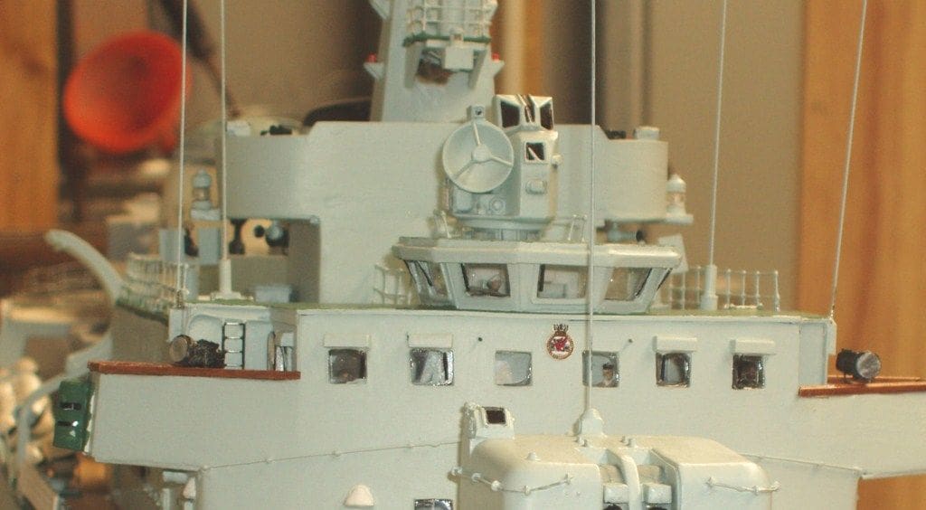
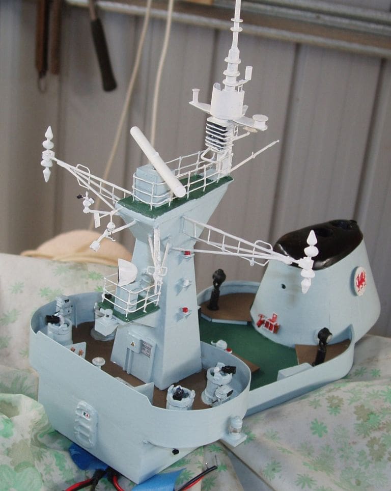
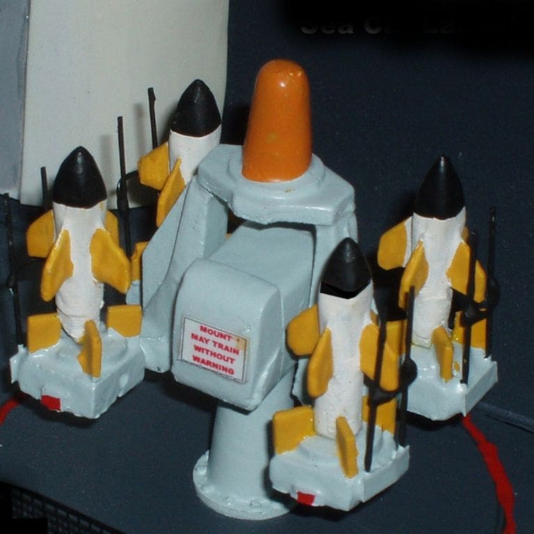
Treating the ship as a series of mini-models made the work seem easier and one could work on different modules if something got boring. For example, Photo 15 is the signal deck and mast ready to be added to the main superstructure unit. Many other parts were built in a modular fashion including the hangar and its interior, Photo 16, the Wessex helicopter, Photo 17, and the Sea Cat launchers, Photo 18.
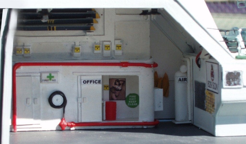
The hazard signs on the model and the Wessex helicopter were created using Corel Draw and Photoshop and then printed on thin glossy photographic paper using a Canon ink jet colour printer. These were all then glued in place and clear varnished to waterproof them.
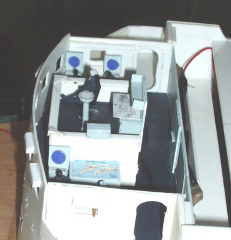
The interior of the bridge is fully detailed although no-one will ever really see inside it. The windscreen wipers on the bridge windows were made by flattening thin copper wire into blades on an anvil and then superglued in place.

Easy attachment?
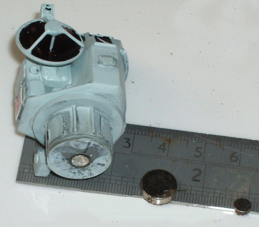
One useful modellers’ trick was to secure many of the easily-damaged fittings on the model with small, yet powerful, rare-earth magnets as in Photo 20. All the gun and missile directors are secured in this way, as are the 4.5 inch turrets, the two Sea Cat and the single Sea Slug launchers. You simply embed one magnet in the main superstructure block or deck and another in the fitting itself, making sure you get the polarity right so they attract each other rather than repel themselves. 3mm magnets were used for the small fittings and 10mm ones for the larger. They grip fiercely and there is the hidden benefit that you can easily rotate the fittings to vary the look of the model. Any ‘wandering hand damage’ repairs are also much more easy to resolve.
Two magnets also keep the Wessex helicopter firmly attached to the flight deck. The magnet in the deck and on the helicopter are not actually in contact with one another, but the attraction force is so strong that it still sticks to the flight deck, even in strong winds, with no apparent hold-down device or ill-disguised bolts.
Ship’s boats and davits
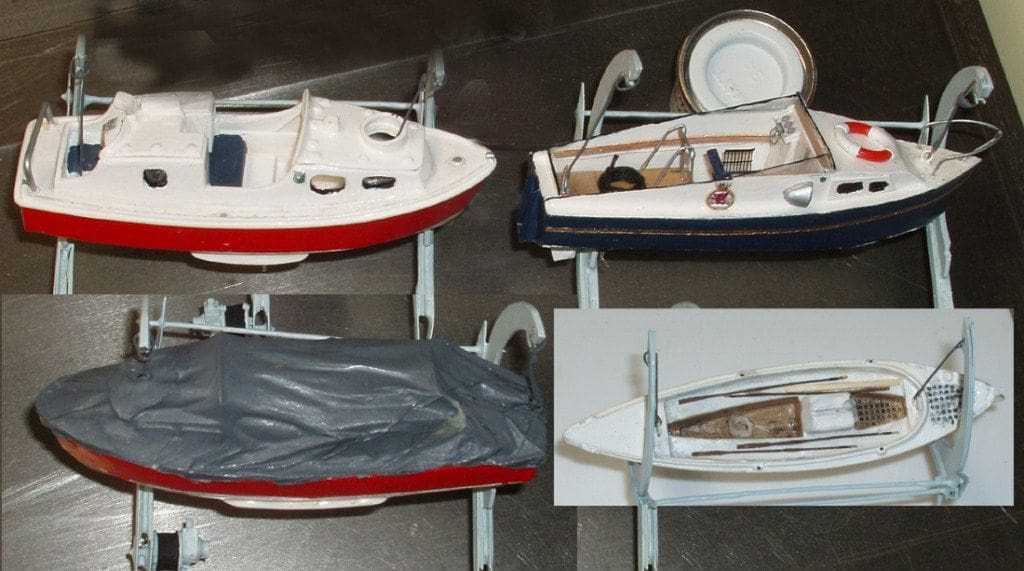
The Cheverton motor launches and the 27ft whaler were assembled from resin castings supplied by Allan Pew (APS) and then super-detailed, but the Fairy Huntress was completely scratch built from plastic card, no kit being available. On the starboard side there is a fully-detailed Cheverton, but I cheated on the port side as the boats are tarpaulin covered. These covers were simulated by Kleenex tissues soaked in PVA wood glue pressed down onto the resin-cast uppers of the boats and allowed to dry. Excess tissue was trimmed off with a scalpel and then the tarpaulins were painted with dark grey Humbrol paint.
Coils of rope in the boats are replicated by rolled waxed cotton thread and the oars in the whaler are small lengths of thick copper wire with the ends hammered flat on an anvil to represent the blades and then painted. Photo 21 is a montage of some of the boats and davit units. The davits are brass photo-etched items from Scale Warship and are really superb. Observant readers will see they have not been assembled 100% accurately, which is not the fault of the makers, but down to me. There are five sets of davits on a County class destroyer and on modern warships of a similar size? Well, virtually none and very often only rigid inflatable boats. How times have changed, but remember that these vessels were conceived over 50 years ago. The davits on the model were also a bit over-engineered for ease of future removal.
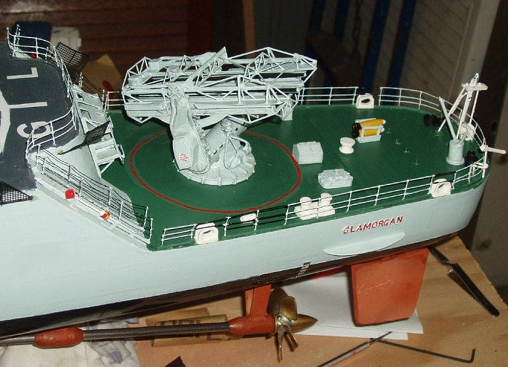
Type 901 radar and Sea Slug launcher
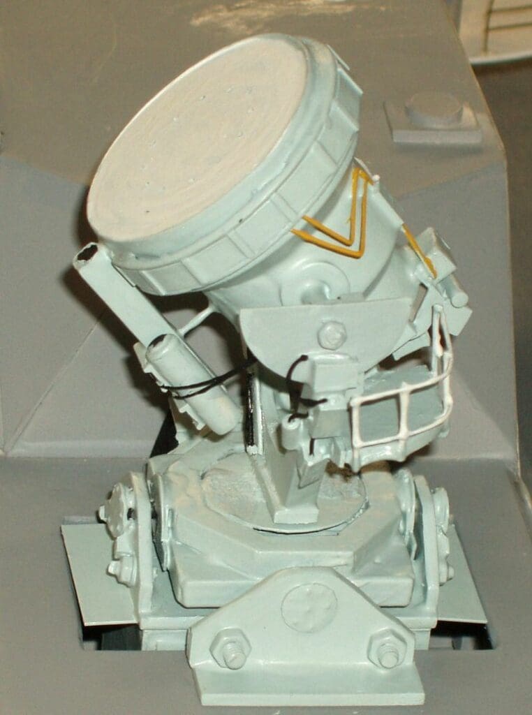
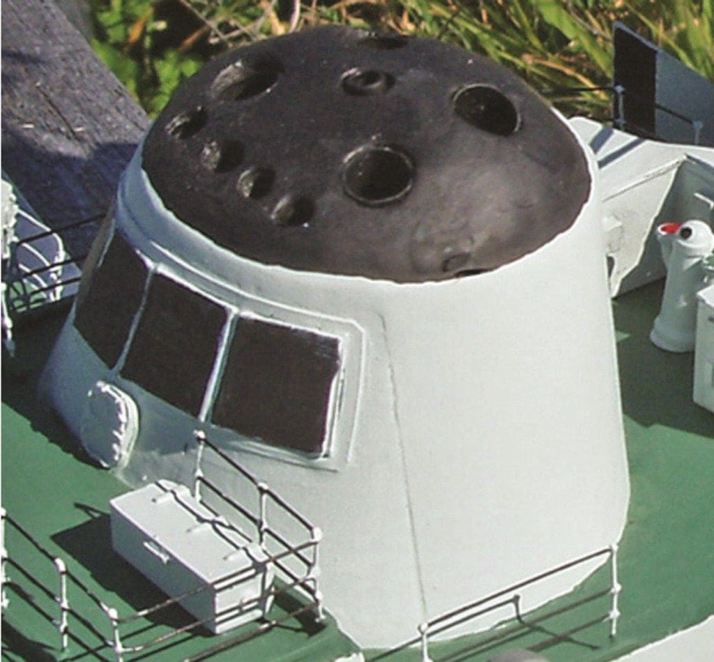
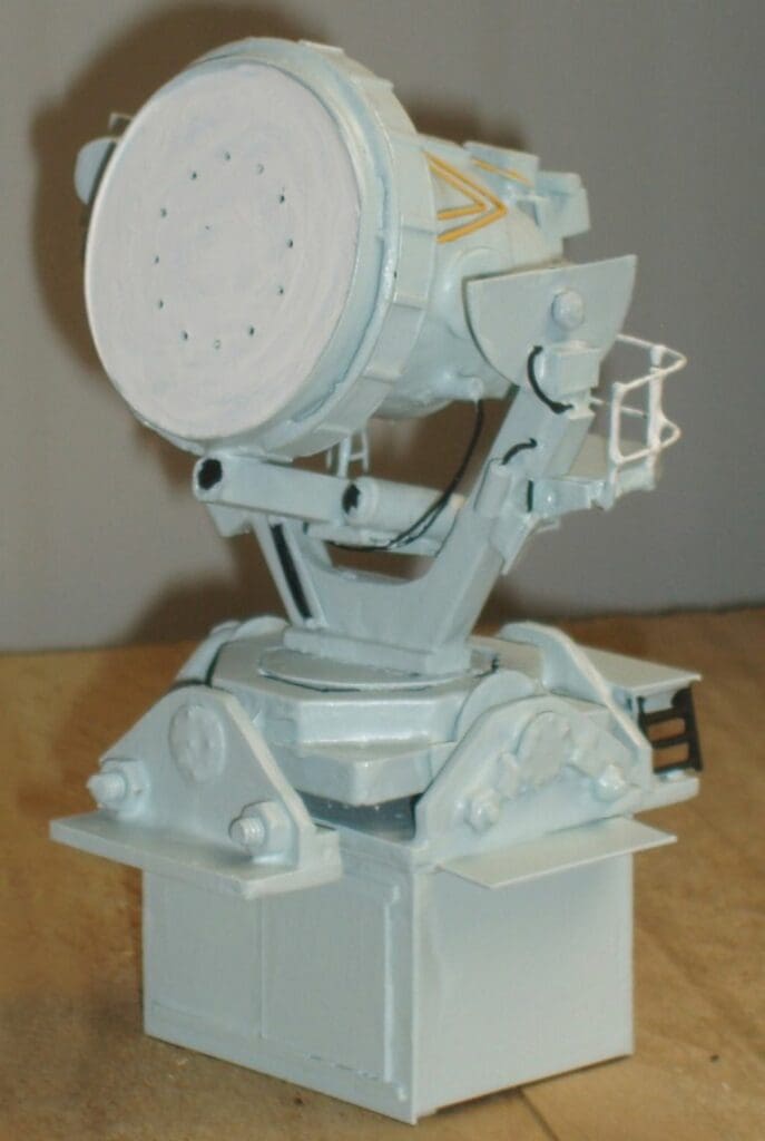
The main surface to air weapon was the Sea Slug missile system. The missile itself was nearly 20ft long, weighed 5000lbs and was designed in the late 1950’s to shoot down fast high-flying aircraft. It was directed to its target by riding a radar beam generated by the equally huge Type 901 Director. The launcher on the quarter-deck at the stern and the Type 901 Director on the roof of an extension behind the helicopter hangar were the most notable features of these vessels and need special attention to do them justice. Needless to say both were very complicated items to build, especially the Sea Slug launcher.
The Type 901 radar, Photo 22, was made from scraps of wood, wire, plastic sheet and the top off a shaving cream pressure pack, but the Sea Slug launcher was even more of a nightmare. At first I tried plastic rod, then plastic rod with wire cores, then brass wire. All efforts to fabricate the complicated hollow box-like launcher were total failures. Fragility was the problem as it had to be almost like a spider’s web to avoid looking over-scale, yet still needed to be strong. In the end, a small local business supplying custom brass photo etched parts to railway modellers was commissioned to create an etched sheet from which I could make up the box shape, but it was not cheap. However, once the basic shape was soldered together, all the fiddly bits and the base could be added without fear the basic shape was going to distort or fall apart, Photo 23.
Running gear and electrics
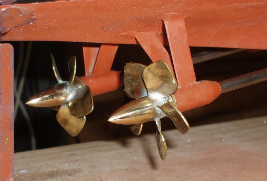
The running gear including the correct style of five bladed propellers, Photo 24, plus propshafts with oiler tubes, all supplied by Allan Pew and was surprisingly easy to install and presented no problems, but some wooden blocks, pre-drilled to the size of the propshaft tubes, assisted in alignment. This was of course all done much earlier in the construction sequence, but there was nothing remarkable in it all. Yes, the motors are not perfectly in line with the propshafts, but it all works okay and sailing duration is fine.
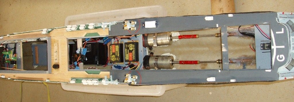
The electrical installation did challenge my skills though. Components are principally from ACTion R/C Electronics (mow via Component Shop) and Electronize. Because three (originally two) sealed lead acid (SLA) 12volt 7ah batteries in parallel are now being used, ACTion’s P103 units prevent back-charging. These feed into an ACTion P92 Power Board which has several 12v outputs and a 5v one to power the receiver. A pair of Electronize FR15HVR speed controllers were obtained so there could be independently controlled motors. With three batteries on line there is about two hours endurance at full power, but slower cruising speeds extend that time considerably. Photo 25 shows the full internal layout and Photo 26 is more specifically of the drive motor area. Please note that only one SLA battery is in the pictures as it is somewhat easier to move the model around with fewer batteries onboard. The Tx is a Robbe F-14 Navy with twin throttle control sticks. The functioning navigation lights use small LED’s and the bridge is also illuminated, to better see the interior, but that is as far as the installed lighting goes. Three of the radar scanners (the Type 965 bedstead on the mainmast and the Type 992 and 1006 on the foremast) are powered and rotate via micro-sized 3v geared electric motors actually located within the radar itself, so there are no connecting rods.

On the water and conclusion
The model when tank tested with the original inclusion of just two SLA batteries, floated upright and at the bottom of the boot topping, a ‘light load’ condition in real life. It seemed quite stable and I was pleased to see it did not need any ballast to correct a list to either side.
However, actual sailing experience on first launch day showed that in fact the model was too lightly loaded and tended to list too much in high wind gusts. So, a third battery was then wired in parallel which brought the total ballast to 6kg. The model now floats half-way down the boot topping which is about right and stability is much better, even with the Type 965 bedstead radar acting like a sail on top of the mast.
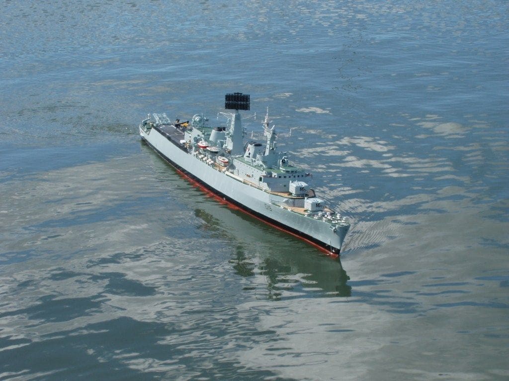
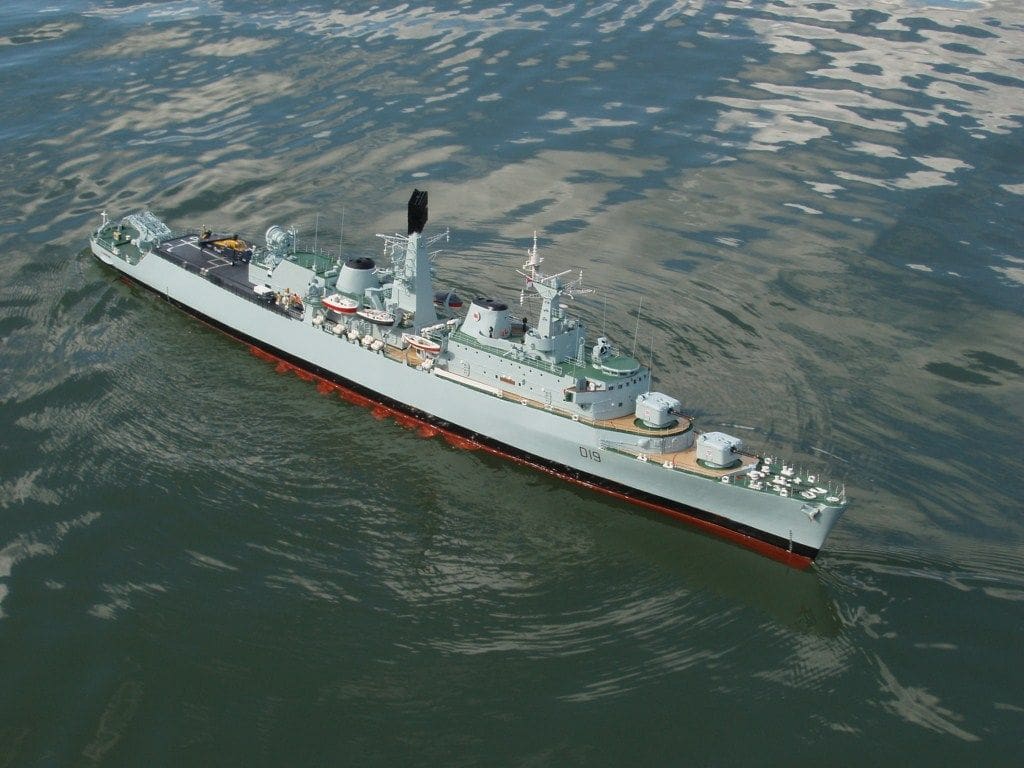
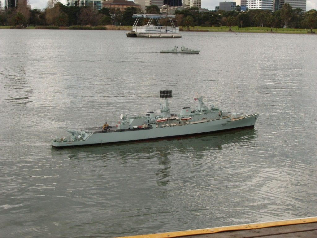
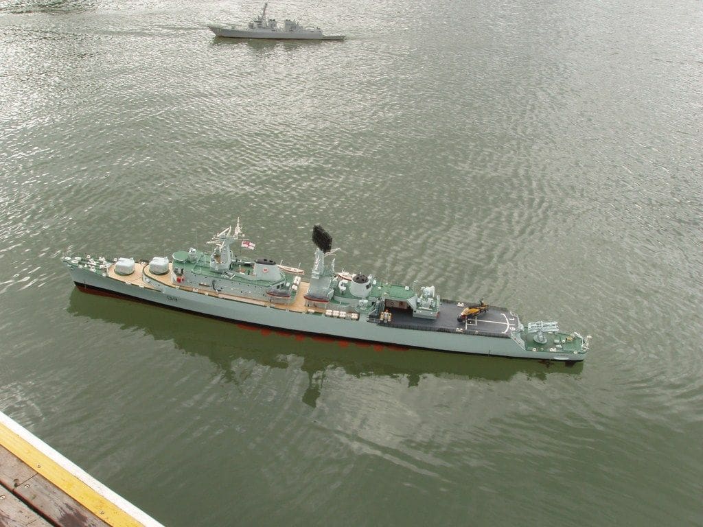
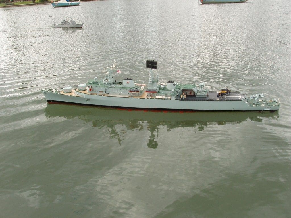
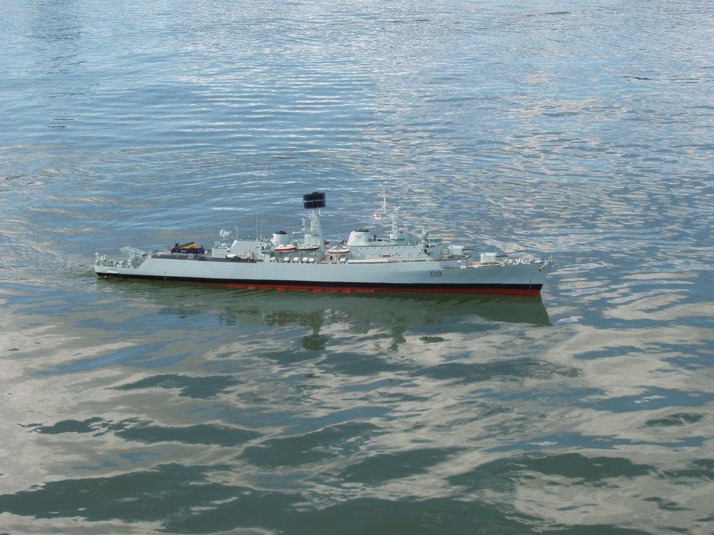
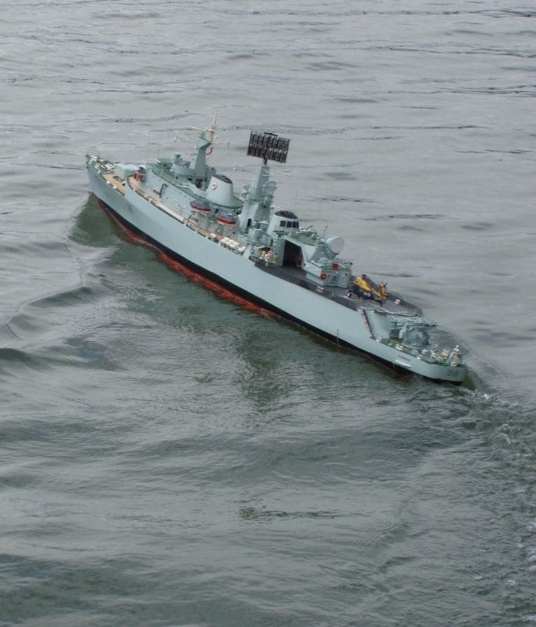
Maximum speed is good too with a nice bow wave, but not over-scale and having two independently-controlled propellers makes the model very manoeuverable. All in all, this model has inherited the excellent sea-going qualities of the original County class warships, Photo 27.
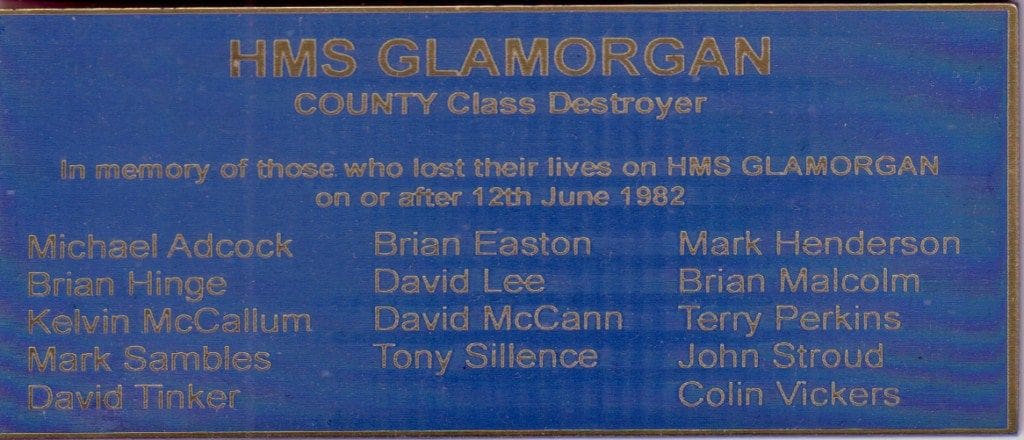
One last thing and that is this plaque, Photo 28, which is displayed on the model when it is out of the water, as a sign of respect for the fourteen men who lost their lives on HMS Glamorgan around the 12th June 1982.
I am very happy with this as my first model boat and have learned so much that I’m hoping to raise the bar quite a lot with my next model, but time will tell.