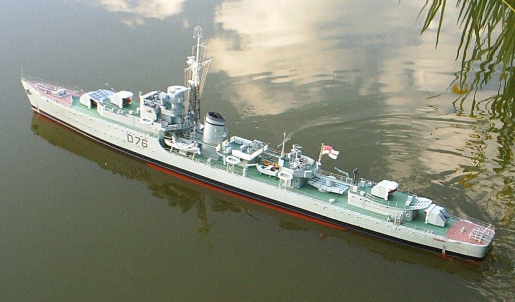
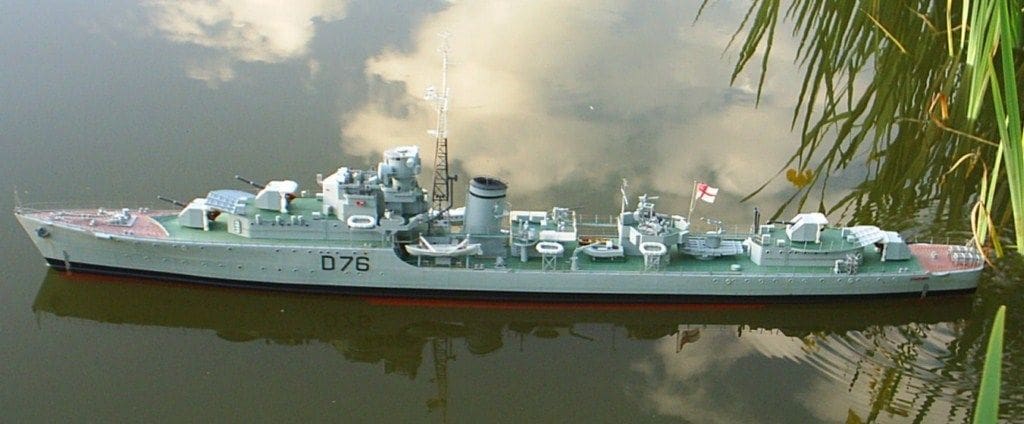
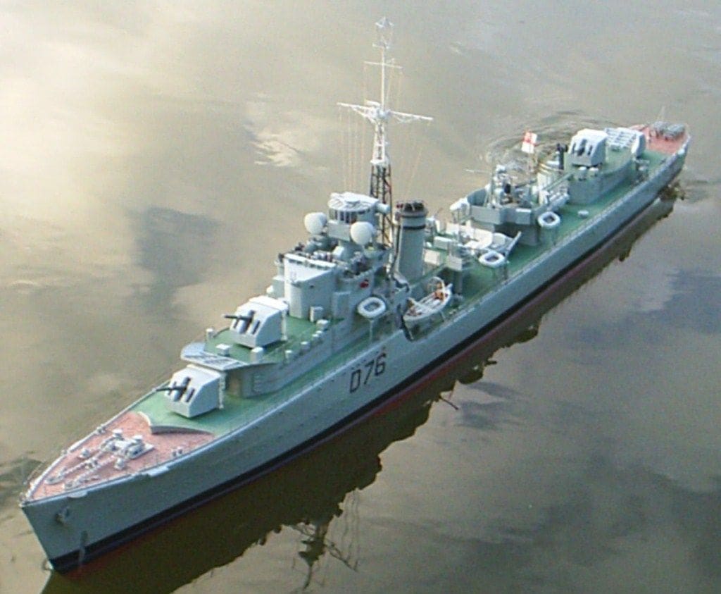
JOHN EDWARDS and his model
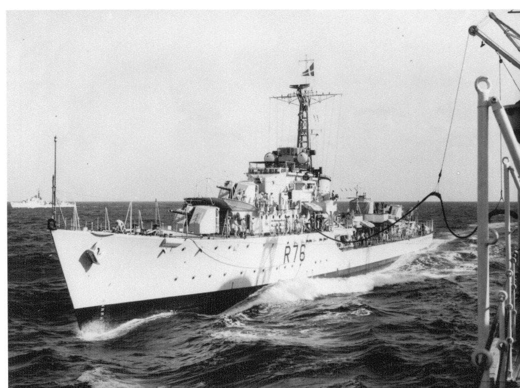
Having already built a minesweeper, a frigate and a cruiser over the last twelve years, shortly before the end of 2009 I decided to add a destroyer to my fleet. It was not too difficult to decide which ship, since the frigate that I had already built was HMS Amethyst of Yangtze river fame, so the destroyer just had to be HMS Consort. The story of Amethyst’s plight on the Yangtze River in 1949 has been frequently told, and of course filmed, but to briefly recap, when the signal came through that she was aground and with many casualties, the first ship to go to her aid was HMS Consort, then in Nanking. Doing 28 to 29 knots on a deserted Yangtze river and with her battle ensigns flying, she must have been an amazing sight. My copy of the film gives a good idea of the very spirited action she fought (the ship playing the role of HMS Consort was actually HMS Teazer). Despite several attempts to get a tow line to the grounded HMS Amethyst and after about three hours of engagement with the Communist shore batteries, she was forced to withdraw or risk becoming a casualty herself. Apparently her guns had done a good deal of damage, but she was damaged herself with a number of dead and wounded amongst her crew.
My model was started just before Christmas 2008, my first intention being a very quick build in time for the 60th anniversary of the incident in April 2009. I had previously resolved to build all my smaller ships to a scale of 1:72, but since HMS Amethyst was 1:96, then HMS Consort would have to be the same. Instead of my usual scratch-build, I had intended to buy a hull and as many ready-made bits as I could to speed things up. However, having seen what was available on the market, I decided to build the hull myself. In truth, I have always enjoyed this work, so it would not be too much of a hardship, just take a bit more time.
Enjoy more Model Boats Magazine reading in the monthly magazine.
Click here to subscribe & save.
The hull
I was spared the expense of buying plans by a fellow Surface Warship Association member, who very kindly loaned me his plans of HMS Caprice, another C class destroyer and although a body plan was lacking, there was a good side profile, deck, superstructure layout and enough stations (cross-sections and/or bulkheads) so that I was able to cut out sufficient frames in 1/4 inch (6mm) balsa to glue to my base board ready for the planking. I won’t go into too much detail of the process because it has been covered many times before and by more skilful modellers than myself! Needless to say though, since a destroyer is a long slender ship it was going to be vitally important to take the greatest of care in order to end up with a completely symmetrical hull.
I have always found the most difficult stage in the process of plank on frame construction to be the relationship of the very top planks to the deck. So when I get to this stage I usually stop planking about half an inch from the top of the frames, remove the hull from the baseboard, and after trimming off the unwanted wood from the top of each frame, glue 1/4 inch balsa strips, chamfered if necessary, between each frame. This not only to provides a platform for the deck proper, which must fit inside the hull, but also gives a stable edge for the very top plank to be glued against. The top edge of the hull it needs to be as accurate as possible if a good rendition of the ship is to be achieved. Generally following this, a good deal of filling of any gaps between the planks is needed in order to give a very firm surface for final sanding and finishing. I usually fibreglass over the whole of the internal space, which makes for hull strength and rigidity and also facilitates sanding the external areas. It is always a pleasing sight to see the crude bow and stern blocks gradually taking shape as the elegant bow and stern of a warship and in the case of this one I was particularly satisfied with the result.
One thing that was lacking was a shell expansion plan (plating details) for the hull, but careful study of many photographs of these ships plus a day out at Chatham Historic Dockyard to visit HMS Cavalier, enabled me to create a plan that I think must be pretty close to the original ship. I followed the usual procedure of cutting up strips of old-fashioned gummed parcel paper and fixing them in place using very thin PVA wood glue. I wish I had the courage to use thin styrene card, but unless there is another glue available, I just could not risk using superglue. I have always found that this very useful product sticks wonderfully well, particularly when the parts are not quite properly lined up, but for some unknown reason, it just does not adhere at all when they are, except of course one’s fingers together!
One thing I particularly noticed from my visit to HMS Cavalier, was the prominence of the deck plating and the way the plates overlapped one another. I had never tried to represent this before and I decided to try to do this using masking tape, with primer to build up appropriate edges. John Lambert supplied me with a deck plan for another similar class of destroyer, upon which I based mine. This process takes time, especially if you carry it on to the superstructure platform decks as well, but I think it gives a good effect and I would certainly do it again on any future ship models.
Superstructure
It is worth mentioning that when building this, I used very thin ply laminated with styrene, but I got caught out a couple of times because I should have looked more carefully at my photographs instead of following the plans. Looking carefully at some of the aerial shots of HMS Consort, I could see that there were a number of differences which I had not noticed before, and I was therefore forced to scrap what had been built and start again.
It seems that some of the deckhouses on the after areas of the ships of the class had different sizes and shapes depending on the number of torpedo tubes mounted. HMS Consort had only one set of quadruple tubes, so without proper plans I had to carefully estimate from the photos the size and shape of these, which was really not too difficult.
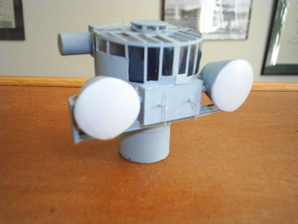
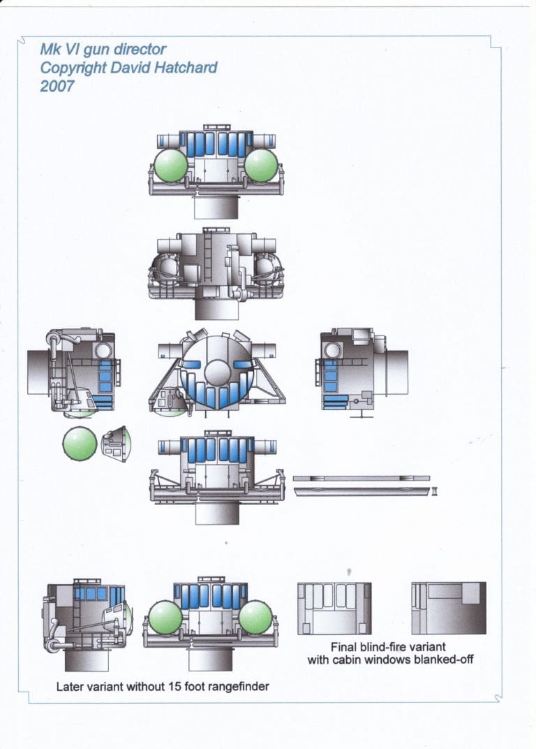
Mark 6 Gun Director and radar
What was difficult was the construction of the Mark 6 gun director. This took about a week, but I was greatly aided by a plan of it that appeared in Model Boats January 2009, Readers’ Models Page 63 and it is repeated here. Since much of the original is clear glass, I started by making the upper part of it with a tube of clear styrene and enclosing it within another tube of white styrene with small strips to show the separate windows. The inside had to be painted a dark colour first, being very careful not to paint surfaces that would have to accept glue. The bottom part is just one of those plastic tubes that once enclosed craft knife blades. Like most modellers, I never throw anything away!
The other troublesome thing to make was the H/F and D/F Frame aerial at the top of the mast. The original is a mixture of odd shapes that somehow come together. I spent a lot of time making sketches of this item until it was clear in my mind exactly how it needed to look, then using very fine wire, it was soldered together in sections before finally being superglued all together. As I wrote earlier, superglue has its positive uses, but also some negative features.
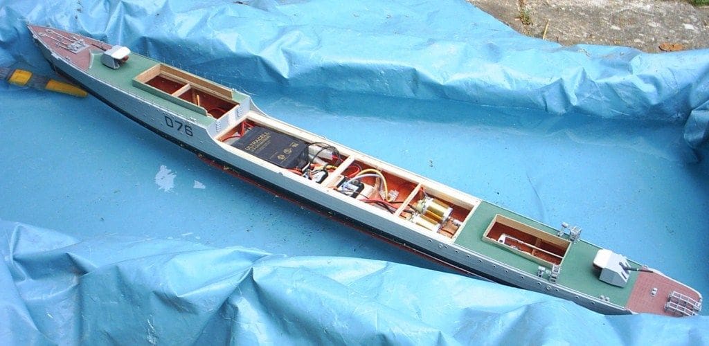
Radio control
While all this was taking place I had been thinking about the best way of using the interior for all the necessities for a working model. There was just enough space for a six volt sealed lead acid battery, which I placed exactly centrally and in the lowest point of the hull, hoping this might be all the ballast required. The receiver is located below the forward superstructure unit which lifts off its coaming complete, and I shortened the aerial, the missing section being incorporated within the lattice mast. The upper decks are in removable sections, held in place by very small screws, which are disguised by bollards and other small deck fittings. I changed the speed controller switch for a much smaller version which is let into the deck and covered by a small motor boat, and following a tip from another SWA member, cut off the Tamiya plugs and replaced them with gold connectors, which I understand are more efficient, and are certainly easier to separate when necessary. Deans Marine Condor motors were the electric motors chosen and the propellers and shafts are from the Prop Shop.
Fittings
Although I had to do a good deal of scratch building of small items such as the Oerlikon guns (one each side of the bridge), two single Bofors mountings abaft the funnel and one single Bofors Hazemeyer mounting, I was able to purchase kits of many other items including ladders from James Lane and other fittings from John Haynes. James Lane advertises in this magazine and John Haynes has a website listing his fittings.
From John Haynes I needed four single 4.5 inch mountings and these made up into lovely little models in their own right, as did the whaler, motor boat and torpedo tubes. His sheets of brass etched items saved me a huge amount of work, especially the depth-charge racks which were a little tricky to assemble, but look a lot more realistic than my usual plastic strip jobs. It is worth noting that a good deal of the weapons of the type carried on this ship are on display at the Explosions Museum in Gosport. Paints were from White Ensign Models, who can supply an authentic RN grey as well as a very good deck green colour.
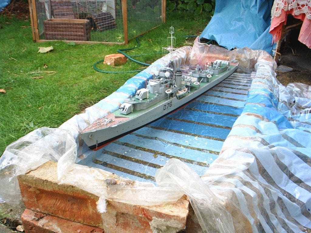
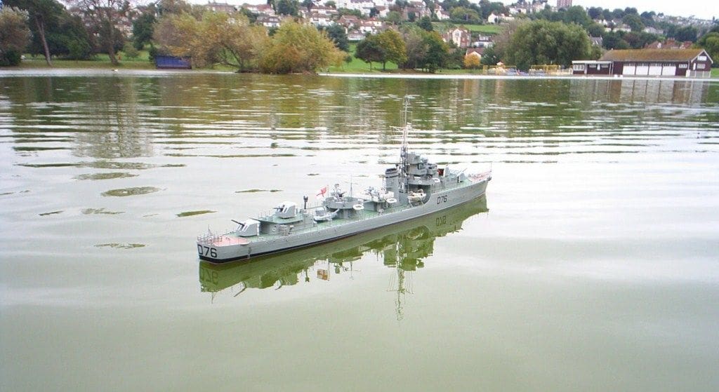
On the water
When the time came to put the model on the water for the first time, I built a temporary pond in the garden using breeze blocks and a pond liner. A little more ballast in the form of small pieces of lead was required, but the model sat well on the water and there were no leaks. Work to finish off the final details continued and she was completed two years after construction commenced, so my target date was well and truly missed!
I got a bit of a shock when it came to the first sailing on a large pond. Having further added to its top weight since the first flotation tests, she was now far less stable and required much more precise ballasting than before, so much so that at one point I doubted that she would ever be a decent working model at all.
However everything came out well in the end and I have had several good sailings with her. The first, being on an overcast Monday morning on a deserted Portishead Lake. The model does look every inch the destroyer, has a terrific turn of speed, is highly manoeuverable and I get about an hour’s good sailing from her, all of which to my mind, more than justifies the time and effort taken.
Conclusion
I must finish by thanking Terry Hodgins of the HMS Consort Association for his patience in dealing with my many phone calls for information. Terry was a boy seaman on board during the action on the Yangtze, but despite his injuries has the happy memories of his time served in her. He is also a contributor to ‘Loyal and Steadfast’ which is a book covering the history of HMS Consort as told by her crew members. Readers may be interested in looking out for this book, as it should be available as a reprint very soon. There is also The Yangtze Incident booklet which provides eye witness accounts of the events of 20/21 April 1949, by the men who served aboard the four ships involved. This booklet gives an entirely different view of the action to that portrayed in the 1957 film.
The HMS Consort Association have a comprehensive website: www.hmsconsortassociation.com where more information may be found. The Surface Warship Association (SWA) have an excellent website for warship modellers: www.surface-warships.org.uk


