With an interest in carrier-based aviation, I have always liked the idea of a remote controlled aircraft carrier. As a member of Task Force 72, Australia’s constant scale model ship association, – now expanding elsewhere in the world too, my interests focussed on engineering this venture in 1:72 scale. (Task Force 72 is made up of a fleet of 1:72 scale models –hence the 72 in the name). My early exploits towards such an endeavour focused on a giant, namely USS Constellation in 1:72 scale. 4.43m long (14.5 ft)! Plug, mould, and hull construction started in 1999 with the assistance of David Rowlands, a fellow Task Force 72 member, and naval architect.
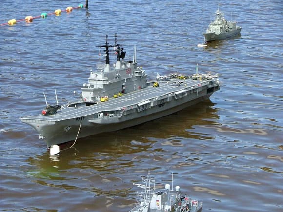
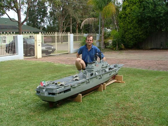
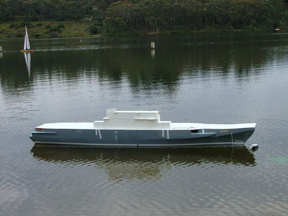
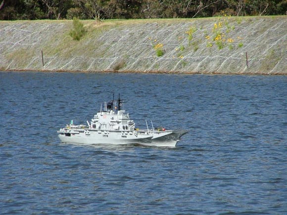
Pic 1: The finished model launched on 26th November 2005 at the Task Force 72 10th Annual Regatta. Pics 2,3 & 4: The finished model launched on 26th November 2005 at the Task Force 72 10th Annual Regatta.
The USS Constellation proved too much for me on my own to finish, and the uncompleted model was sold in 2004 to a Royal Australian Air Force, Air League leader, who with a number of team members will complete the project. The biggest problem I faced working on my own was that the 90 plus kilograms of fibreglass hull kept aggravating a lower back injury. So sadly she had to go.
Enjoy more Model Boats Magazine reading.
Click here to subscribe & save.
My wife, who first got me into the hobby, had mixed emotions seeing such work leave unfinished, and encouraged me to build something else, although that was not hard. Specifically, I have always loved Harriers, and I started researching the history and deployment of these aircraft at sea.
The British modern light carriers are well represented in Task Force 72, and I was aiming my research at something different. I started looking at Giuseppe Garibaldi and was impressed at the look of the ship, her armament, and her air wing. I decided to build her as she was in the year 1995.
Giuseppe Garibaldi
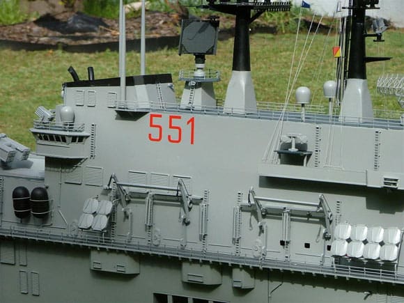
Giuseppe Garibaldi C551 is the Italian Navy’s flagship. She was built in Italy in by Italcantieri, launched in 1983 and commissioned in 1985, and has an expected service life to 2016. At 180.2 meters long (591.2 ft) she is the world’s smallest aircraft carrier to operate fixed wing jet aircraft. She is also armed to the teeth and this light carrier has been sometimes referred to as an aircraft carrying cruiser. Indeed the designation “C” in her pennant “C551” I have been told refers to her cruiser like status.
Giuseppe Garibaldi has three twin barrelled Breda director controlled guns for close-in weapon defence and multiple batteries of chaff launchers. The Bredas are 40mm rapid-fire guns with the manufacturer claiming that the twin barrelled version fitted to Garibaldi fires at 900 rounds per minute and can kill an incoming supersonic missile flying in a straight line at ranges as great as 3 kms. The Breda automatically switches from the lighter high explosive round to the heavier depleted uranium round when the missile reaches a range of 1 km.
Garibaldi also carries the Honeywell Mk 46 Torpedo and A290 torpedo that can be fired from two triple 324mm launchers for anti-submarine warfare (ASW). Packing a big punch are surface-to-surface (SSM) Ottomat missile launchers, and two octuple Albatross pack launchers for Aspide surface-to-air (SAM) missiles. The SSM capability and volume / variety of weaponry is unusual for light carrier status, and hence the cruiser designation may be reflecting this. In 1994 I understand that the SSMs numbered eight Ottomat launchers, and by about 1996 these were cut back to four. All of them have since been removed.
The ships air wing primarily carried 18 Sea King SH-3D helicopters, but these are being replaced by Merlins. The ship can carry 16 AV/8B Plus II Harriers, the first of which arrived in 1994. Carrying all 16 would not leave room for helicopters so usually a mix of Harriers (10 is usual) and helicopters is carried. The hangar does not extended through the ship’s maximum width or run its entire length and is therefore limited for servicing aircraft.
Garibaldi’s design was built in order to satisfy requirements of having a ship equipped with fleet command and control characteristics, and for the optimal use of aircraft, anti-ship and anti-aircraft missile weapon systems. In later years she has served as an amphibious command ship launching landing craft. The ship’s four gas turbines propulsion system provides a maximum speed of 30 knots and at an economical speed of 20 knots her range is over 7000 nautical miles.
The ship’s flight deck is 174 metres in length and 30.5 metres in width, and the forward 15 metres of the flight deck rise up a gentle ramp of six degrees. The ramp angle is problematic whereby the AV/8Bs face difficulties deploying full combat loads of fuel and ordinance. The Invincible class ski-jumps at 12.5 degrees should have been a good lesson for the Italian’s to note. The newly launched Italian “Conte di Cavour” light carrier features a ski jump of 12.5 degrees and a much larger more efficient hanger space.
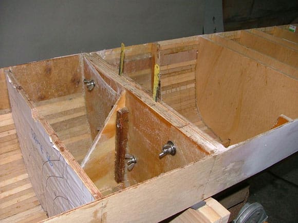
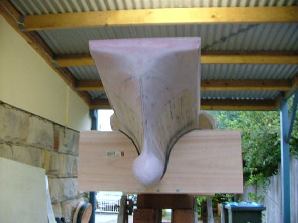
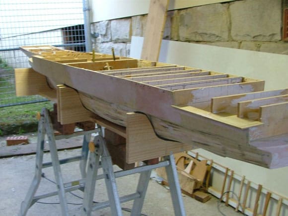
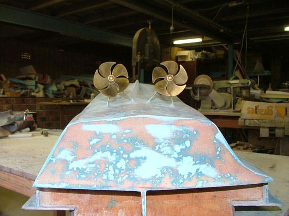
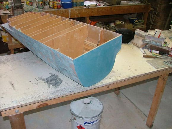
Pic 5: Inner hull joints showing triangular bracing to keel. Pic 6: Early bow construction. Pic 7: Hull nearing completion prior to fibreglassing. Pic 8: Stern half of hull inverted with running gear installed and fibreglassing complete. Pic 9: Forward bulkhead of stern half of hull inverted.
Giuseppe Garibaldi C551 Specifications as at 1995 (year modelled)
Date Deployed: 1985.
Launched: 04 June 1983.
Commissioned: 30 September 1985.
Function: Light aircraft carrier / cruiser. Italian Navy’s Flagship.
Expected service life: To be retired in 2016. Conte di Cavour, launched in 2005 (ex – Andrea Doria) is scheduled to take over as flag ship.
Displacement: tons 10100 standard, 13850 full load.
Length: 180.2 m.
Beam: 33.40 m.
Draft: 6.70 m.
Speed: 30 knots maximum, 20 knots typical.
Range: (nautical miles) 7,000 at 20 knots.
Complement: 550 + 230 air group + 45 flag staff .
Propulsion: 4 x GE/Fiat LM-2500 gas turbines (80.000 hp ), 2 shafts.
Radio call sign: IAIQ.
SAM: 2 Albatros Octuple (48 Aspide Missiles).
CIWS: 3 twin 40 mm Breda.
SSM: 8 Otomat SSMs.
Torpedoes: 2 triple 324 mm torpedo tubes (Honeywell Mk 46 torp / A290 torp.).
Aircraft: 16 Harriers AV/8B plus II / or 18 SH-3D Sea Kings, 10 Harriers usual.
Radar (Air search): Hughes SPS-52C, 3D, E/F bands, range 440 km; Selenia SPS-768 (RAN 3L),D band, range 220 km; SMA SPN-728, I band, range 73 km.
Radar (Air/surface search): Selenia SPS-774 (RAN 10S), E/F bands;
Radar (Surface search/target indication): SMA SPS-702 UPX;
Radar (Navigation): SMA SPN-749(V)2; I band;
Radar (Fire control): 3 x Selenia SPG-75 (RTN 30X), I/J bands, range 15 km (for Albatros); 3 x Selenia SPG-74 (RTN 20X), I/J bands, range 13 km (for Dardo); IFF: Mk XII; Tacan: SRN-15A.
Sonar: Raytheon DE 1160 LF, bow-mounted, active search, medium frequency.
Countermeasures Decoys: SLQ-25 Nixie; 2 x Breda SCLAR 105mm launchers (chaff and illuminates); ESM/ECM: Elettronica Nettuno SLQ-732.
Planning the model
Obtaining plans did involve a little digging, but after an enquiry to www.modelwarhsips.com forum page, an Italian modeller in Rome kindly pointed me in the direction of ANB, (Associazione Navimodellisti Bolognesi), which is the Bologna Maritime Model Association. ANB is an excellent source of ship plans, and are the largest single repository of ship plans that I have come across. They hold over 1,600 sets of plans, from ancient days to the present, and the range includes, merchant vessels, cruise ships, warships, tugs, and many more categories. Subjects, as you would appreciate are mainly Italian, but there are scores of non Italian ships’ plans too. Worthwhile checking out is their website at www.anb-online.org. Whilst in Venice on holiday in 2004, I picked up a hardcopy of their catalogue of plans for 45 euros. This catalogue is known as “Tecnica Estoria Attraverso I Piani Costruttivi Navali” which essentially means the Technical story and plans of maritime construction. See http://www.anb-online.org/page_info.php?cPath=2015&products_id=3840 for further details. Most of the plans held by ANB are in fact the original shipyard’s plans. In addition to purchasing the plans, I was able to download a plethora of photos from the Internet. (Of course you need to be aware of local and all applicable international copyright laws when doing this.) Caution needs to be applied in obtaining lots of photos as such an approach invariably gets you photos from different time periods and I have found quite a bit of differences in structures and fittings over the life of the ship thus far. Indeed the latest version of Jane’s Fighting Ships 2004/05 at my public library shows the ship with superstructure now extended on the starboard side to be almost flush with the extremity of the flight deck.
I found that my local public library was by far the cheapest place to print off photos that I had in electronic form. My decision to build Giuseppe Garibaldi in 1:72 scale came from my want to keep my fleet in the one scale and thus aligning her in the ranks of excellent company at Task Force 72. The availability of aircraft models in 1:72 scale supported that decision. In 1:72 scale, Garibaldi is 2.5m long (8.2 ft) and a lot more manageable for myself to build on my own than the USS Constellation in that scale. Right from the start I planned the model to have a hull that could be split into two watertight halves for transporting and re-joined via two watertight bulkheads.
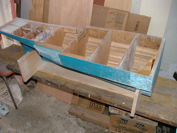
Pic 10: Forward bulkhead of stern half of hull right way up. Pic 11: Forward hull section. Pic 12: Detailing looking rearward from the forward starboard side.
Hull Construction
Within two weeks of my enquiry to ANB, Giuseppe Garibaldi’s plans arrived in a package the size of a small telephone directory. The 84 Euros were worth it. The plans were to 1:100 scale and were clear and crisp in terms of their readability and fine detail. The plans were an exact copy of the builder’s plans.
First order of business was to increase the size of the plans to 1:72 scale. I made multiple copies of the frames for the number of frames of the ship. Cutting out these, I glued these to 6mm marine ply sheeting.
Using a jigsaw, the marine ply frames were cut out. The frames when cut out were done so with allowances for planking the hull, fibreglass, and gel coat. This was done so that the hull’s extreme widths would be accurate in scale. The cut out frames were positioned vertically and upside down on a building base at the correct spacing apart. The frames were held in place by pressure holds of timber pieces forward and aft of each frame. Each frame had a pre-cut groove in its base to accept a dove tailed fit of a 20mm piece of Tasmania Oak (hardwood), which served as the keel.
Thin (2.6 mm) marine ply planking 12mm wide was then used to plank the hull with waterproof Selley’s Aquahere (wood glue) and pin nails.
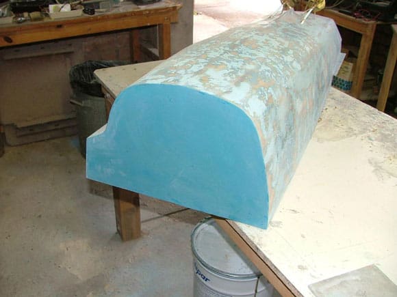
The bow and stern were formed up with a combination of horizontal and vertical cross sectional frames, marine ply planking and surfboard foam. Surfboard foam areas were covered with a thin layer of waterproof car filler.
After sanding and ensuring the hull was true, I sent the hull off to Allan Pew of APS Models. I commissioned Allan to laminate the hull’s exterior with fibreglass and gel coat and supply the running gear, two shafts, A frames, stuffing tubes, and brass propellers. The inner hull was coated with an oil-based enamel.
During the hull construction, I installed two solid frames side by side at a point close to the midpoint of the hull’s length. Two hacksaw blades spaced a thin 1.2 mm gap between these two frames. This was done, as it was my intention to cut the hull in half at this point so as to allow ease of transport of this 2.5 metre model. The hull would be reconnected together with six stainless steel bolts, spring washers, and wing nuts. These were installed prior to cutting so as to ensure a perfect rejoin after. The two frames had triangular pieces of marine ply extending from the flight deck level to the keel and adjoining the frames. This was done so as to transfer any load stress from the joined frames to the whole of the hardwood keel fore and aft in both hull sections. The gap, pre-spaced by the hacksaw blades allowed Allan after fibreglassing to make a uniform cut through the hull.
The construction time of the hull took 34 hours, with another 12 spent on tidying it up, sanding, etc., prior to fibreglassing. To keep my costs down, I only commissioned Allan to do the fibreglassing and gel coat so I spent another 12 hours post his fibreglassing, smoothing / sanding the brushed gelcoat finish. I was very happy with how well and fast this came together, although quick construction speed was not sought out, it just happened that way. I certainly did not want to rush this at all. I am sure my experiences learned working with David Rowlands on USS Constellation coupled with a great set of plans from ANB, helped me on this project.
Running Gear
I got this from Allan Pew of APS. The 5-blade props are brass, and are 70mm in diameter. By the way I should mention that Allan Pew’s APS Models is the premier 72nd scale supplier here in Australia, and I would probably guess that he is the largest 72nd scale supplier of ship kits and fittings internationally. Allan has no less than 100 semi kits in 72nd scale on offer, and hundreds of accompanying 72nd scale moulded fittings. Indeed, I cannot think how Task Force 72 could exist to the degree it does without Allan’s commitment, dedication and skill over the years.
Fittings
Where APS didn’t have the one that I wanted, I made masters of parts and Allan obliged by moulding them and reproducing them in great number. Allan even made the master for the Otomat SSM launchers.
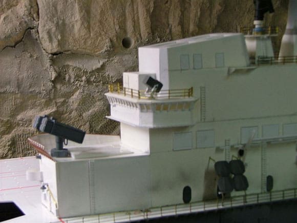
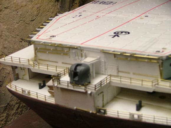
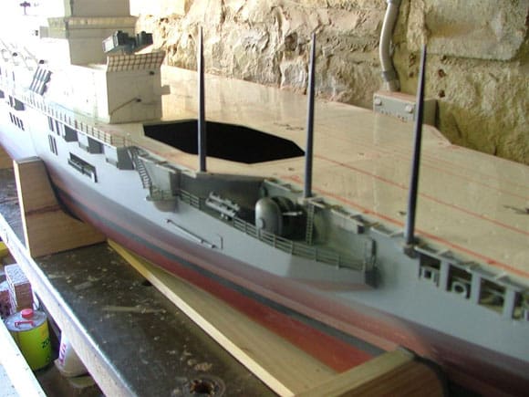
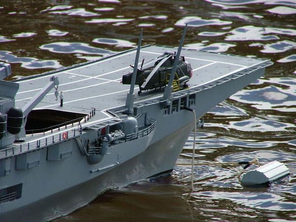
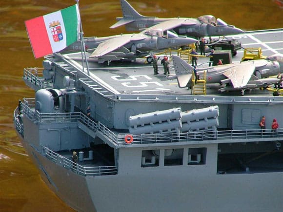
Pic 13: Sea trials at Task Force 72 Regatta in November 2004. Pic 14: Detailing of rear starboard side of superstructure showing Octuple launcher for surface to air (Aspide) missiles. Pic 16: Stern showing Breda Twin 40mm close in weapons system. The sponsons left and right extremes are the positions for the surface to surface (Otomat) missiles.
Flight Deck
The flight deck is made from 3mm styrene sheet. A few people have said that they thought that this would not be good to have a large plastic expanse in the hot Australian sun, but sea trials conducted in November 2004 (last month of our Spring), indicated no problems with the deck heating up at that time. The deck was unpainted at that stage and the white styrene would have been efficient at reflecting heat. The ship was launched with the deck painted and the opposite (attracting heat) did occur. Unfortunately the deck under the heat did buckle in a few places and a repair to this flaw is underway. The deck is made up of six removable sections. So the whole deck can be removed section-by-section if needed. Only two sections need be removed to access the batteries. The deck is held in position by 3mm stainless steel round head countersunk bolts that mate with nuts installed in the top outer sections of the hull. An electric screwdriver can replace or remove all the bolts in under two minutes.
Radio Gear / Speed Controls
I purchased from R2 Model Marine here in Australia, two of the latest Electronize FR15 type microprocessor speed controls and a Robbe-Futaba F14 Navy Twin Stick Radio. The twin sticks are used for independent port and starboard motors. Garibaldi has a single large rudder that makes the model quite manoeuvrable. The twin sticks for independent throttles allow the model able to turn in its own axis, via going ahead one side, and astern the other.
Motors and Power
I bought two Buhler motors from Task Force 72 Treasurer Michael Brown. Michael was kind enough to conduct tests on these motors with the brass propellers made by Allan. The motors are coupled straight to the shafts (direct drive). These have a good turn of speed with the model measuring about four knots flat out (33.94 knots scale speed) over a measured distance. An in water test of full speed ahead for both motors with the model tethered showed a max amp reading of 10.9 amps using a 12 volt sealed lead acid battery. I use two 12 volt 18 amp hour batteries so this maximum current drain is acceptable given the 36 amp hour capacity. Most of the time I drive at around all ahead two-thirds speed so the drain is somewhat less.
Elevator / Lifts
A single large hydraulic piston drives each of Garibaldi’s two aircraft lifts. I chose to go with a scissor mechanism, as I had earlier failures with the single piston system. The Task Force 72 Brisbane membership had past experience with aircraft carrier lifts on 1:72 scale Invincible class carriers, and 1:72 scale Hornet and Yorktown carriers. After my early failures, and not wanting to re-invent the wheel, I commissioned Jim Russell (TF72 Brisbane) and co-owner of Model Submarine Systems Australia (MSSA) to construct two lift mechanisms. Jim went to work on this and I ended up with a brilliant mechanism that includes a shock-absorbing damper that eliminates any vibration to aircraft on the lift. After a few hours of modifying Jim’s mechanism to get the right height and fall of the lift, I was able to fit both lifts into the hull to mate with the openings cut in the flight deck. The lifts are controlled by servos linked to independent switches on the F14 Robbe-Futaba Radio. Servo slows are employed to control the speed of ascent or descent. Eventually I plan to link these mechanisms to independent servo controlled timers so the lifts will work automatically and independent of the radio control.
Air Wing
One thing I learnt very early on was that plastic kit manufacturers have local releases of products aligned with the countries that they are released in and often if you are not in one of these countries those products will not be available to you. For example, its not surprising to find a string of FA/18 Hornet kits released here in Australia with Australian decals, as these are the primary Royal Australian Air Force fighter, yet these kits with the Australian decals are harder to find abroad. Similarly, the Hasegawa AV/8B Plus II 1:72 Italian Navy version was not available in Australia. I could only find them on European websites, and in abundance in Italy naturally. So I imported the kits to Australia. I bought six of these. The really great thing about the Hasegawa kits is the individual aircraft numbers of Garibaldi’s aircraft embarked were supplied, which I believe adds to the realism. Soon after I had purchased these kits, Airfix released the trainer version (TAV/8B) with multiple decals, including the Italian Navy. I picked up one of these, as I understand from Jane’s Fighting Ships and from photos from the net that Garibaldi typically deploys with at least one TAV/8B on board.
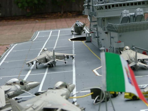
A good friend is a former Grumman test pilot and self-confessed plane nut (Commander David “Hound” Karonidis US Navy ret). The Commander kindly constructed all fixed wing aircraft except for the trainer He has done a fantastic job on these and I am truly grateful. He built each of the aircraft with different ordinance, and in different settings, such as flaps at different angles, canopies closed or open, aviator on board or without. This greatly improves the realism of the flight deck. One AV/8B Harrier is set up with the thrust nozzles down, flaps down, with aviator on board and the canopy closed. This Harrier actually flies. Well it appears to fly by being linked to a clear retractable nylon rod, linked to a nylon cord pulleys and a servo. This is linked to a proportional slider channel, so the scene depicted can show a vertical take off, hover, steer, hover, and vertical land. Whilst the vertical takeoff is not really operationally correct on the carrier as the Harrier utilises a short roll take off over the ski-ramp, the aircraft sometimes do this manoeuvre, especially if the forward deck is crowded or the aircraft is on a training sortie. Having said that, the realism is in the landing. To make this realistic, I sail out away from close sight, I get the Harrier airborne, and then sail back towards prying eyes and commence the landing.
Superstructure
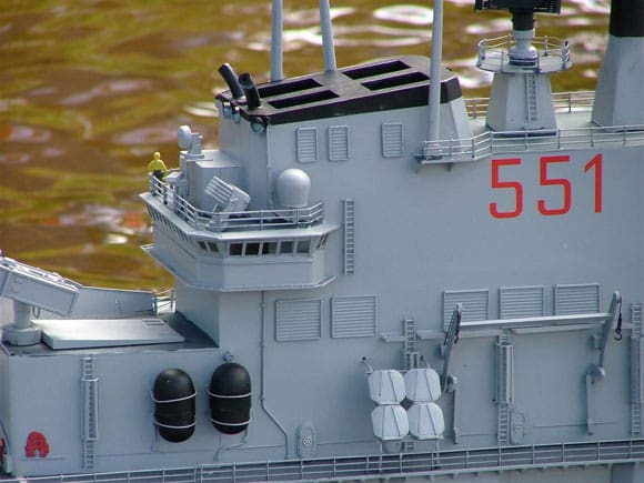
The superstructure was constructed from 1mm, 1.5mm and 2mm styrene sheets, as well as a variety of Evergreen plastics. This was a relatively easy build, compared to previous works I had undertaken on other models. I made sure to combine the plans, which were the original builder’s plans circa 1984, with the photographs I had of her around 1994. Typically a lot of change occurs following sea trials and there will always be some noticeable differences, as refits / upgrades, etc., over a ship’s life result in inevitable change. Changes made on or around 1997 included a port side extension of the rear superstructure as after three years of operating Harriers changes were made which enabled better views of the flight deck when landing. This structure might be similar to what the US Navy might call a “pry fly” area. Further changes, and probably the most noticeable change to the superstructure, occurred around or after 1999, when two large whaler type lifeboats / general-purpose boats, their derricks and equipment, were removed from the starboard side of the superstructure. I am glad I modelled her in a year with these features still on board. I understand these were removed as they were almost completely under-utilised with two motor launches in the port and starboard side boat pockets being used extensively. Moreover, should a disaster befall the ship, life raft packs capacity on board more than exceed all travelling personnel.
The superstructure is bolted down to the flight deck utilising removable panels of the Aspide missile magazines for and aft.
Logistics
Transporting the model is done in two large marine ply boxes for each hull half, another box for the superstructure, and another for the aircraft with foam packing around each aircraft.
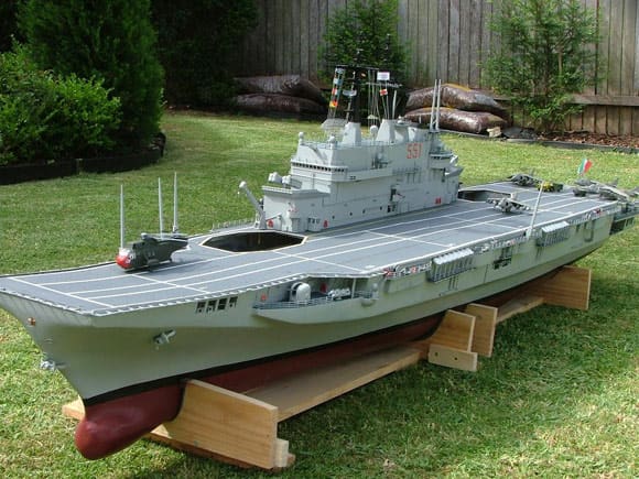
Pics 17 to 20: The finished model launched on 26th November 2005 at the Task Force 72 10th Annual Regatta.
Conclusions
Despite scratch building a hull prior to this project with the help of David Rowlands, most of my other projects have been semi kits and therefore scratch building for myself has been limited to building superstructures and fittings. This project is a first for me in that it’s the first time I have started with literally nothing but an idea, and with some sub-contracting of features along the way, ended up with a complete radio controlled scale model packed with features.

