DAVE BRUMSTEAD with r/c scale news
Welcome to this month’s Focus on Scale. In this issue we are paying a visit to the Essex Country Show and looking at drive motor alignment and couplings. We are also having a look at a model speedboat designed and built by an aeromodeller and looking forward to the Model and Craft week at Thornwick Bay.
Essex Country Show, 12/13 September 2009
Enjoy more Model Boats Magazine reading in the monthly magazine.
Click here to subscribe & save.
This event at Barleylands near Billericay in Essex is a super family event, primarily with lots of steam traction engines and farming displays, but also with a very nice lake in the middle of it all. The 2010 event will be on 11/12 September, website: www.essexcountryshow.co.uk. As in previous years, the model boating activity in 2009 was arranged by the Southend Model Power Boat Club who invite a number of local clubs who are able to display inside the marquee. Please note that it is by invitation only, therefore individuals cannot just turn up and sail on the day.
There were several model boat clubs in attendance, with the usual cross section of scale, semi-scale and kit built models. This type of event really helps to promote the hobby to the general public who are also given the opportunity to see the models in action on the water.
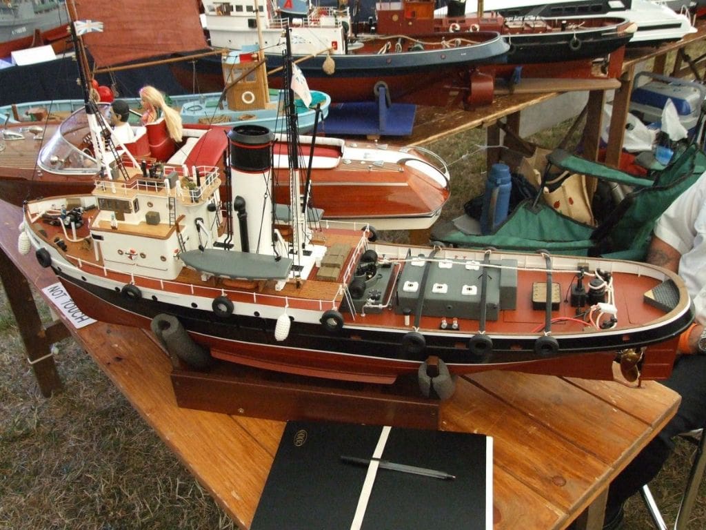
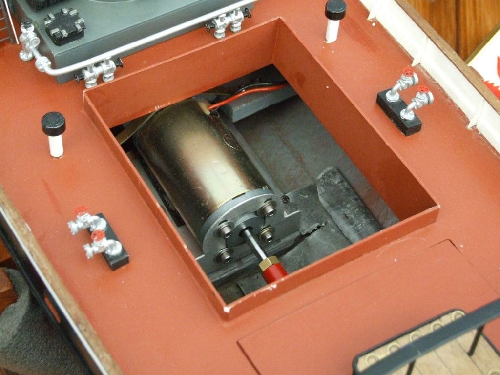
The first model we stopped to look at was the Englishman, built by Mike Smith, secretary of Greys Thurrock MBC, Photo 1. This is based on the Model Slipway kit of the Envoy class tugs. This type of tug was used during the war and afterwards they were sold into civilian service and renamed. The model, at a scale of 1:48, is 1108 mm (43 1/2ins) long with a beam of 248mm (9 3/4ins). Mike had installed a 21 pole Buhler drive motor, Photo 2, with Spektrum 2.4Ghz radio and a 20 Amp Mtroniks Viper esc.
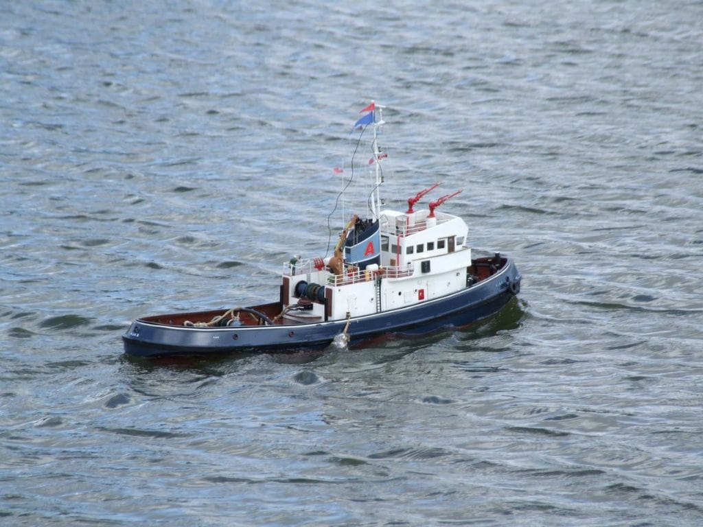
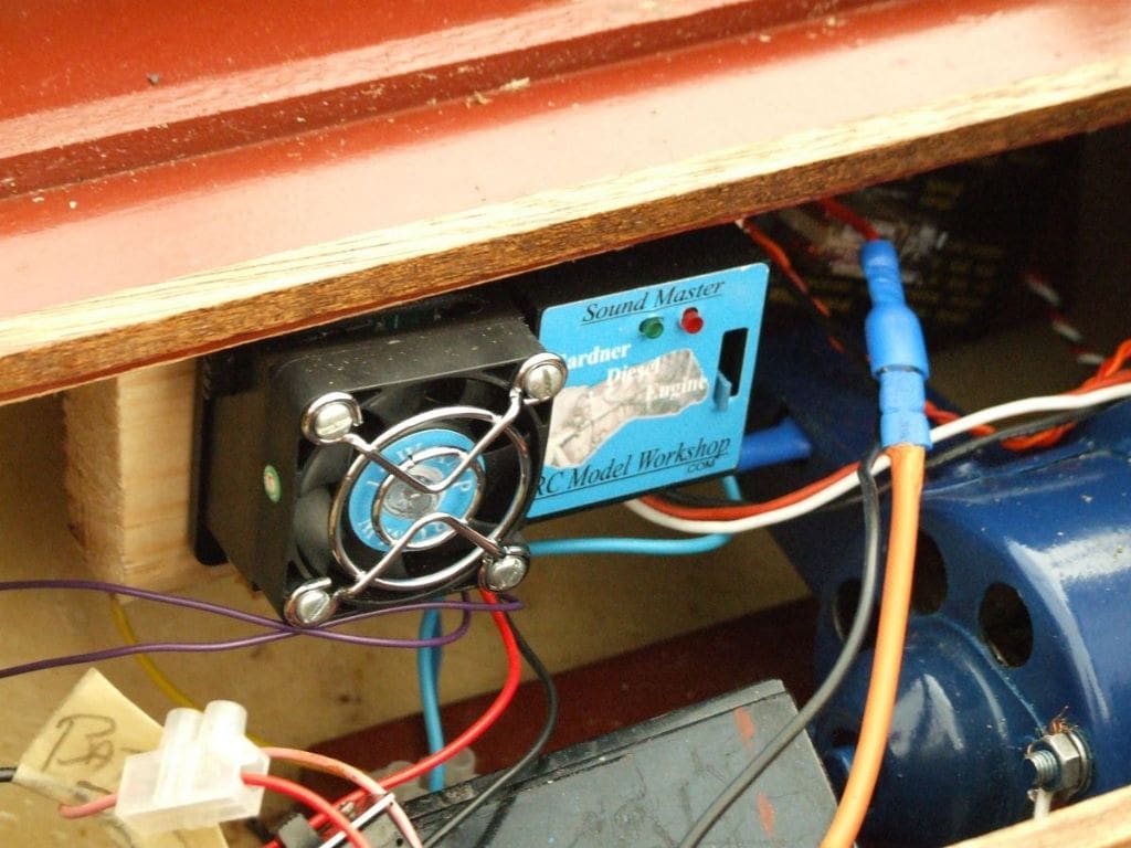
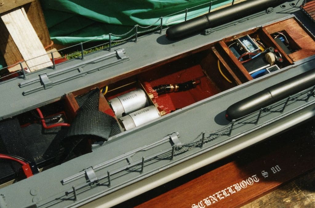
Pictured making headway against the wind on the lake was this fine model, Ajax, Photo 3. Built by Alan Tomlinson based on a Tyne Models Flying Phantom hull, Photo 4 shows part of the inside of the model. Just in view, bottom right, is the drive motor which comes from a van refrigeration unit, hence the 12v operation. Hitec 27MHz radio is used together with a Mtroniks Viper 20 Amp esc. A RC Model Workshop sound unit is fitted with a 30 Amp amplifier.
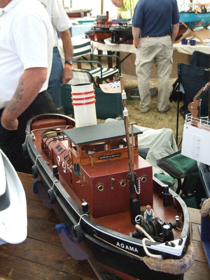
The Agama, full size, was owned by Gaselee and Sons and built by Alexander Hall and Co. in 1937. Photo 5 shows the model built from sheet wood by Ray Black who worked on the full size vessel. The model has a Graupner 900 drive motor, Spektrum 2.4GHz radio, a Ripmax esc and two 12v 7 Amp SLA batteries wired in parallel for power. The full size vessel was used as a supply vessel to the pirate radio ships that operated in the Thames Estuary and in July 1966 towed the pirate radio ship Cheetah 2 into Harwich after her anchors dragged. Ownership of the Agama was transferred in 1967 and the vessel was scrapped in 1970. The model is now owned by Les King.
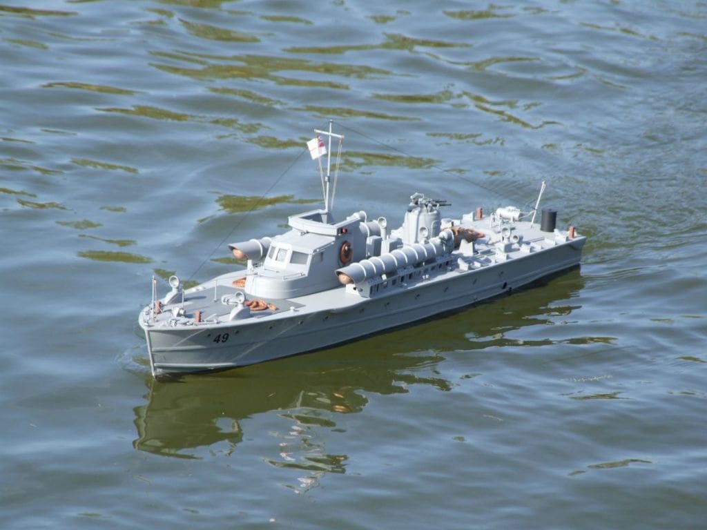
One of the models at the show from our own Brentwood MY&PBC was this fine model of MTB 49, built by Paul Freshney, Photo 6. The model was based on a 1:24 GRP hull from HSL Mouldings. Some of the fittings were also from this source, notably the Vickers 0.5 inch twin machine guns and turret, the smoke generator, torpedo tubes, and cowl vents.
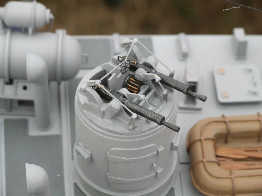
Other fittings were from Precision Controls but the torpedo tube rails, hatches, bollards, mushroom vents, mine racks and fairleads were cast from resin in moulds made from Paul’s own masters. The cabin and bridge are from styrene and painting is by airbrush with subtle weathering. Propulsion is by two 6 to 12v Buhler motors running on 8.4v. Spektrum 2.4GHz radio is installed with an Mtroniks esc and the model took eight months to build. Although not visible in the picture, the rudder linkages pass through the transom and since water can enter the hull through these openings, a watertight stern compartment is incorporated to prevent the whole hull filling with water. The full size vessel was one of a class of eight ordered in 1939. Length was 75ft 9ins including the trailing rudders, beam 16ft 6ins. Propulsion was by four Thornycroft 650hp engines driving two shafts and the maximum speed attained was 29 knots. Photo 7 shows some of the detail on the model.
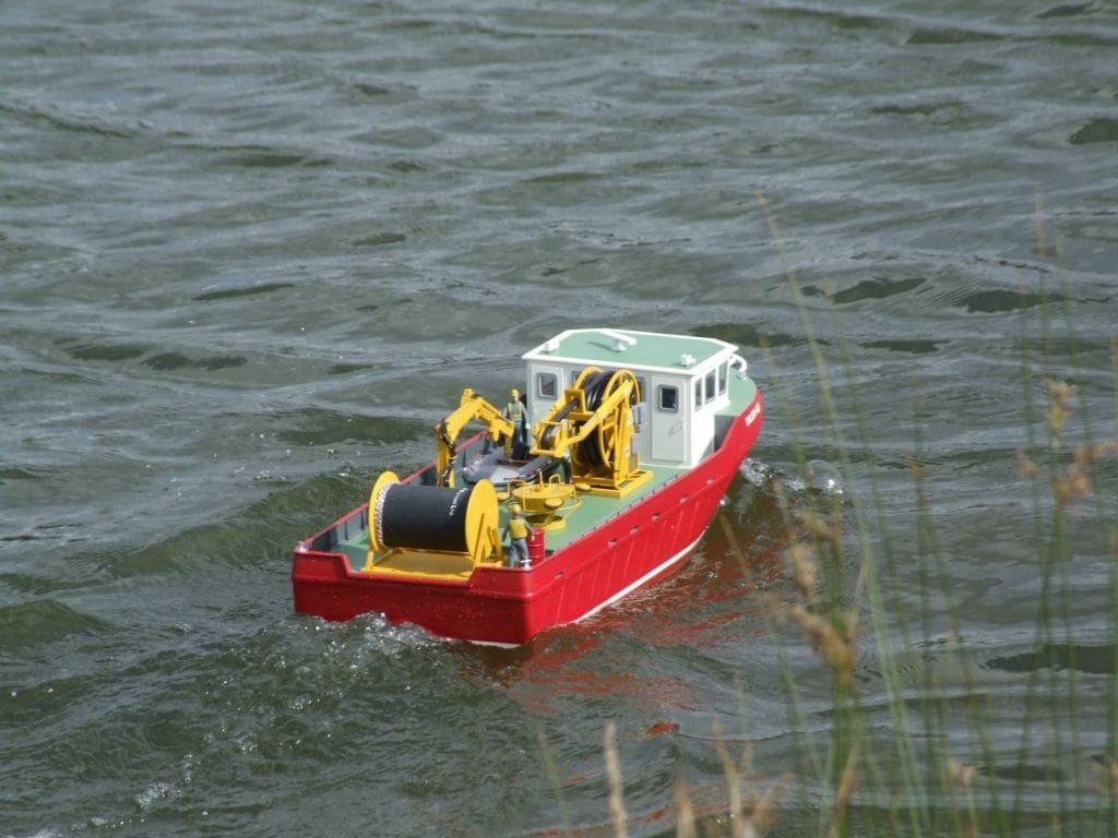
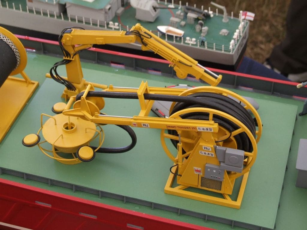
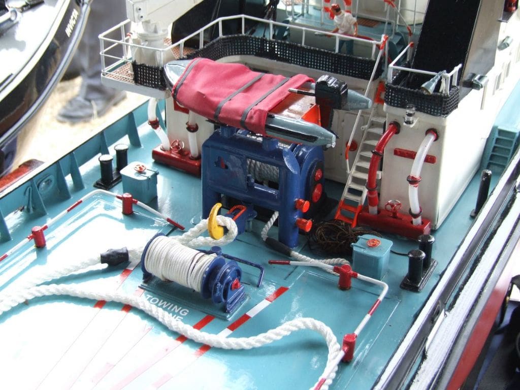
Another model on our stand was an unusual vessel from John Elliott. OILON –H₂0 is a freelance oil recovery vessel seen underway in Photo 8. The model is based on a hull from Deans Marine and is equipped with replica oil spillage recovery equipment, Photo 9. The full size equipment, Transrec 250 by Framo of Norway, is an automatic containment and recovery boom/skimmer, designed to be operated by one man. The oil spill is contained by a boom deployed from the reel at the stern of the vessel. The skimmer, the round disc with four floats seen left of centre in the photo, is placed in the oil spill and various services, hydraulic lines, electrical cable and cargo hose, are connected to it. The spill is pumped through the cargo hose into the vessel’s waste recovery tanks. The model uses Spektrum 2.4GHz r/c with Mtroniks esc.
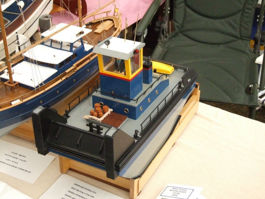
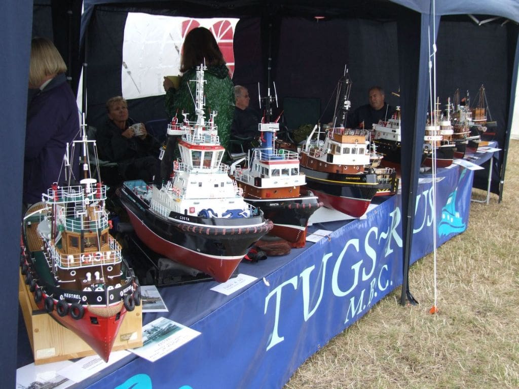
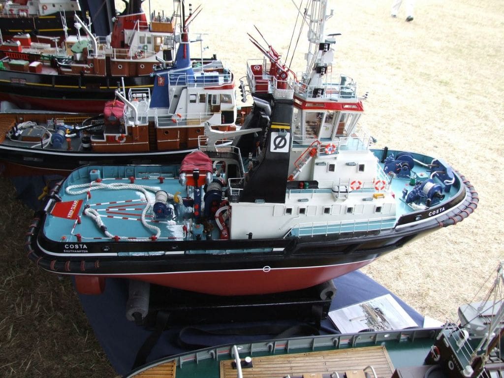
Over on the Wat Tyler MBC display, James Goodall had his Springer pusher tug on the stand, Photo 10. This very nice 24ins by 11ins model was scratch built and uses two 540 motors for drive with an ACTion esc and Futaba 40MHz r/c. On the Sunday, the second day of the show, another contingent of modellers arrived. As the marquee was already full of clubs with models, ‘Tugs R Us’ set up their own gazebos outside the main marquee entrance and Photo 11 shows part of their display of fine tugs. As we were spoilt for choice, it was a difficult choice to decide which model to feature, but in the end Dave Frith’s Costa was the one we chose, Photo 12. Dave’s model is based on the Mobile Marine Models’ Ayton Cross hull which is 42ins (1060mm) long with a beam of 14 3/8ins (365mm). Drive comes from two MFA 800 motors with belt drive reduction of 2.5:1 driving 75mm props in steerable nozzles. Spektrum DX6i 2.4GHz r/c is installed and the model has working lights and fire monitors. Photo 13 shows some of the detail on a model which took just seven months to build, not bad at all!
Motor alignment and couplings
Over the last two issues we have looked at various methods of mounting the drive motor in the model. So far so good, however the difficult part may come with aligning the motor shaft to the propshaft. With modern universal joints a small degree of misalignment may be acceptable, but good engineering practice tells us that these two shafts should really be aligned as accurately as possible. Photo 14 comes from my archive, but it shows two couplings joined together to bridge a large discrepancy between the motor output shaft and propshaft. Many years ago when I first started in this hobby, small drive motors could be connected to propshafts with the rubber tube from a bicycle tyre valve, but there is no chance of doing that here!
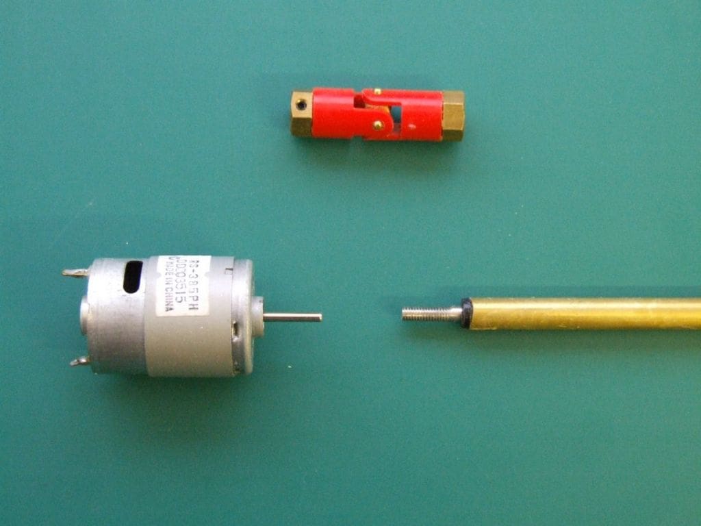
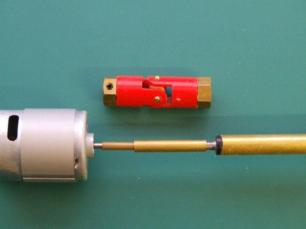
So where do we start? Photo 15 shows a 385 motor and the propshaft to which it is to be connected and the intended coupling. The first step is to either find a piece of brass tube that fits snugly over the motor shaft and another to fit over the propshaft, or if you have the facilities, to turn and drill a piece of brass rod to suit. The two pieces of tubing should be fitted together as in Photo 16 with the total length the same as the coupling. The two tubes may be soldered together to make a totally rigid tube which can be kept for future use.
If you prefer a double coupling or a different type of coupling, the length of this joining piece should match. Although lying on the bench the motor and propshaft are aligned as they would be in the model with sufficient clearance on the propshaft to fit a locknut and washer. Mobile Marine Models manufacture an alignment tool, Protorlign, which has a variety of ‘jigs’ to align standard propshafts and motor output shafts. For more information, please see their website: www.mobilemarinemodels.com.
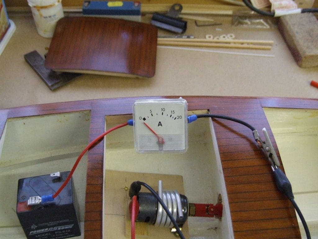
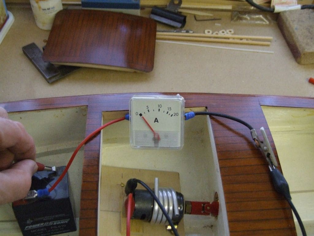
So, at this stage we have a suitable mount for the motor and a tool to ensure a reasonably accurate alignment of the motor to the shaft. Photo 17 shows the motor installed and connected with its coupling. There are a couple of methods that may be used to check that the alignment is as perfect as possible. The first, illustrated in this last picture, is to connect an ammeter in series with the motor and a battery. As you can see the motor is not yet connected to the battery and the meter pointer is reading below zero. When the motor is connected, the pointer moves a very small amount, indicating that the motor is drawing little current, as it should do as there is very little load on it, Photo 18. If the motor mounting screws are slackened enough to move the motor by hand and the current reading drops lower, the motor alignment has improved and that is probably as close as you will get to perfection. Small packing pieces may be required to hold the ideal motor position when the mounting screws are tightened. The second indication of improved alignment is that the motor speed should also increase.
Always ensure that there is sufficient slack in the propshaft to coupling to motor output shaft assembly to allow the outer thrust washer (between the propeller and the stern tube) to take the thrust, rather than the motor output shaft and its bearings.
As far as couplings are concerned, these like many other areas of our hobby, have evolved over the years. In the 1950s and 1960s most couplings were designed for i.c. powered boats.
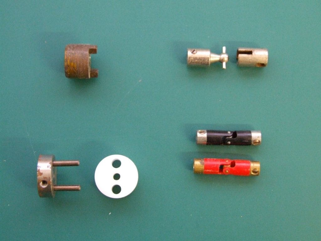
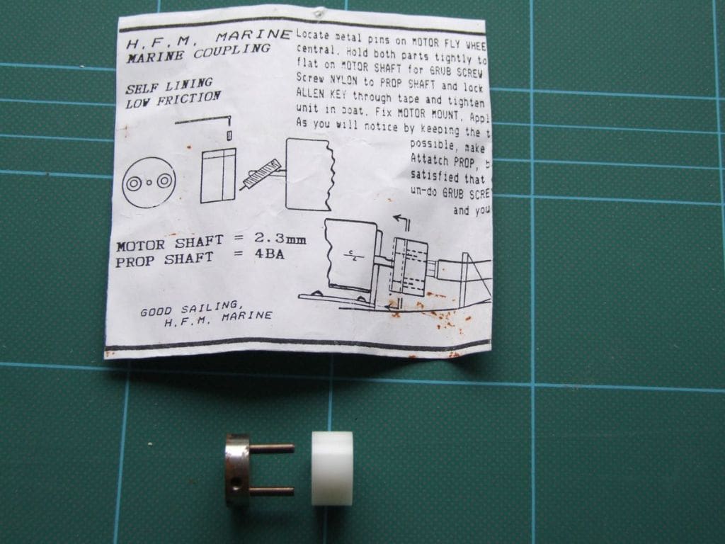
The top two couplings in Photo 19 were used for this purpose, the one on the left was fitted to an E.D. Bee 1cc diesel engine. The lower couplings on the right were distributed by Ripmax in the 1970s. The bottom left coupling, seen also in Photo 20, was manufactured by HFM as part of the running gear kit for their range of vac. formed model boat kits. Having one part manufactured from plastic reduced the possibility of metal to metal electrical ‘noise’ being generated which could interfere with the radio control.
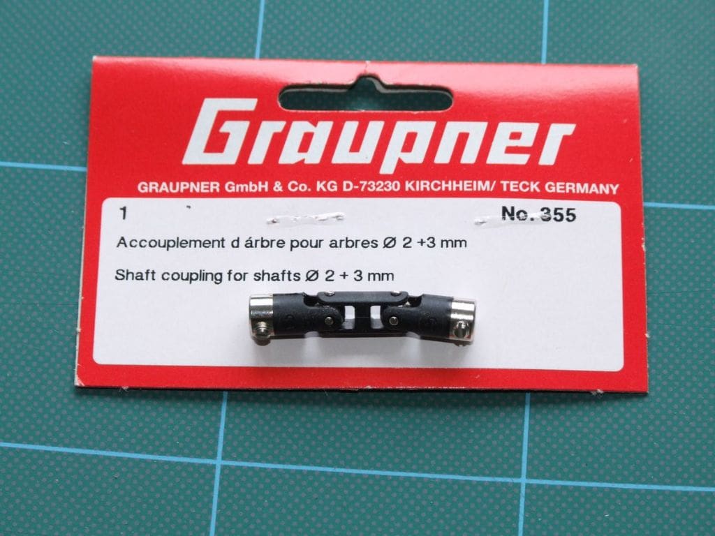
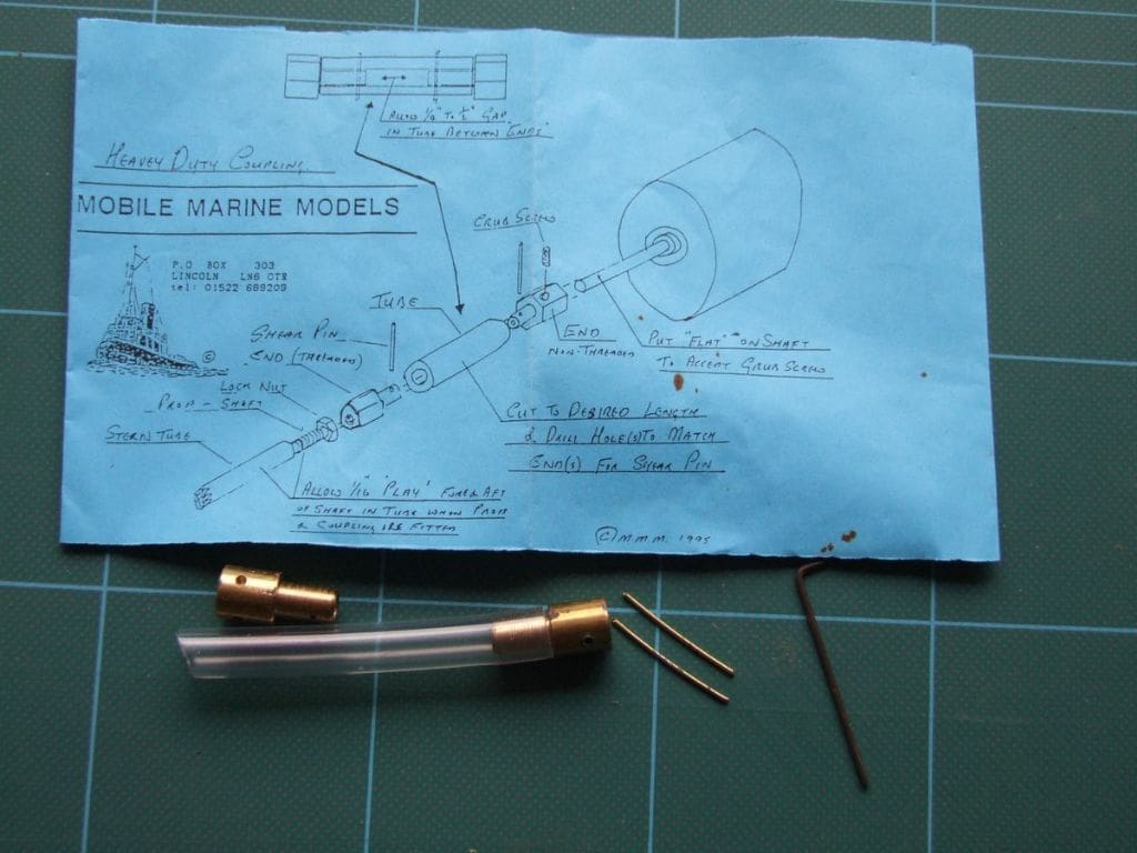
Photo 21 brings us up to date with a typical modern coupling manufactured by Graupner which consists of two ends with a joining piece in the centre. Photo 22 is of a slightly different type of coupling manufactured by Mobile Marine Models. This consists of two brass end pieces which are fitted to the motor and propshaft. These are joined by clear plastic tubing which is held in place by two brass pins. These are fitted by drilling through the plastic tube and the brass end pieces. As the coupling is designed for relatively high torque tug motors, should the propeller become fouled, then the pins shear to protect the motor from being overloaded.
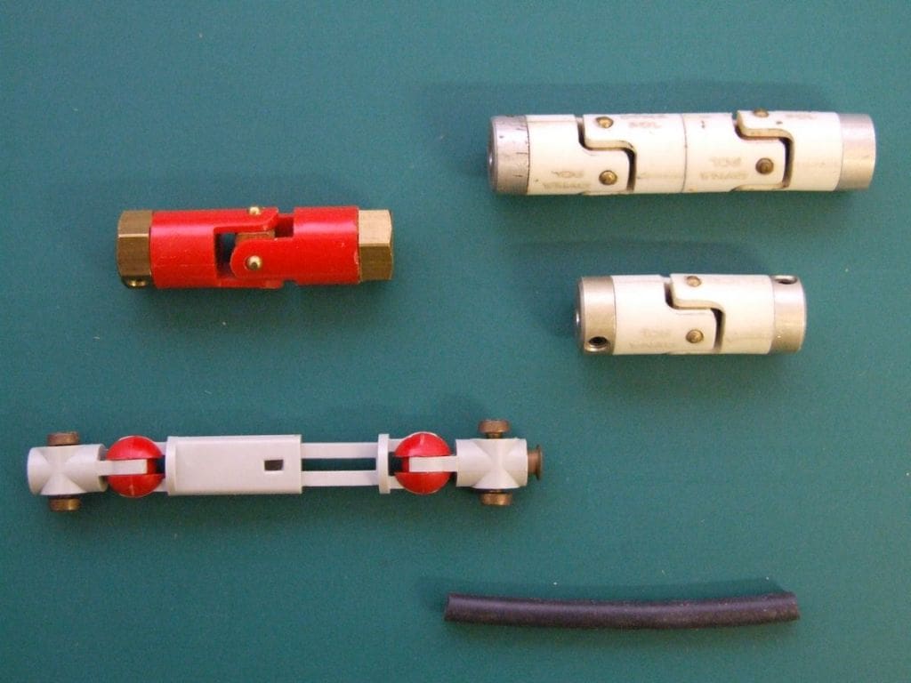
Photo 23 brings this article on couplings to its conclusion. This shows most of the couplings in common use today with the Dynapol coupling top left, two Huco couplings top right, with the upper version consisting of two plastic parts joined to increase the amount of articulation. Bottom left is a Graupner Kardan 4 coupling which can bridge a gap from 67mm to 85mm. A smaller version (for 2mm shafts) is also available. I first came across one of these some years ago used in conjunction with a variable pitch propeller where the propshaft slid up and down the prop tube to adjust the propeller blade pitch from forwards to neutral to astern.
I mentioned earlier on in this piece that a piece of rubber tubing used to be used to join small drive motors to propshafts. The tubing, bottom right in this last picture (Photo 23) serves the same purpose. This is manufactured by Robbe and is 5mm x 1.2mm x 50mm and comes in packs of ten pieces and they can be readily be cut to length.
There are other types of couplings I may well have omitted from this summary, like the Taplin coupling, SHG and the spring coupling seen in Photo 10 in the February issue, but I have attempted to cover those currently in use in r/c scale.
Michael Binnersley, aeromodeller
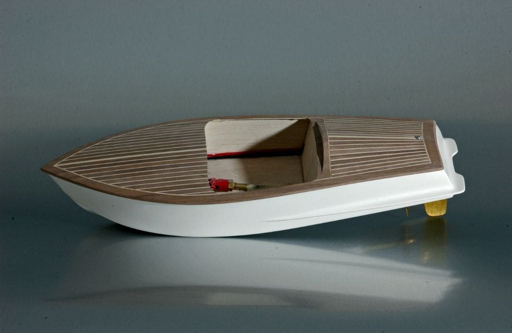
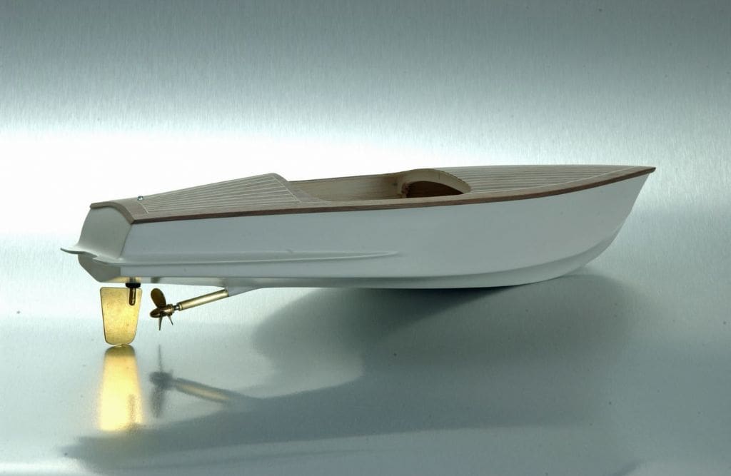
Whilst visiting a trade show in Harrogate, I was introduced to Michael Binnersley who was there for the aeromodelling element. In conversation he told me that he had built a model speedboat with the plans ‘out of his head’ In due course the following photos were forwarded to me. Photo 24 gives a general impression of the model with major construction from balsa with a GRP skin and a walnut and sycamore deck. The screen surround has yet to be made, Photo 25, but will be from walnut and brass. The model has a 380 motor with NiMH power which is to be upgraded to a brushless motor with a LiPo battery for power. It is always nice to see model makers crossing the threshold!
Thornwick Bay Model and Crafts Week, 2010
I recently spoke with Jim Worner, organiser of the Thornwick Bay week. The 2010 dates are 24th April to 1st May. All the scale regattas and free sailing are in the evening on the indoor pool, plus there will also be sessions for tanks and indoor helicopter flying with sessions for yachts, i.c. and fast electric models off site. The handicraft programme starts from the Monday of the week. For full details, please contact Jim Worner, evenings only, tel: 01423 862971 and for site bookings, please telephone: 01262 850369. For 2010 there will be Mini-ship towing with the tugs restricted to a length plus beam not to exceed 24 inches, single screw, single blade rudder (max area 1.5ins) and must be of traditional design. Photo 26 shows the 2009 tugs, Lindberg, Airfix, Graupner, SHG and one scratchbuilt.
That’s all for this month, so happy modelling! If you wish to get in touch, please do so via the Editor or email: [email protected]


