The tug Ayton Cross currently serves on the River Tees in the North of England and is owned by Wijsmuller. Bryan Ward of Mobile Marine Models asked if my colleague and I would build a plug from which he could make a master mould and thus produce grp hulls. The hull for which the timber plug was made measures 42ins long by 14ins beam and will draw about 7ins of water when loaded to the waterline. The timber plug for the hull of Ayton Cross was made in my workshop and cost 138 hours to build using frames and keel of 6.0mm thick plywood and planks of 3.0mm ply. It was built in the plank-on-frame manner and all release slots, ports, anchor box and bow thruster locations were marked upon the master plug.
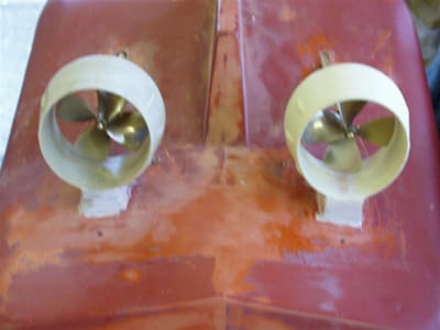
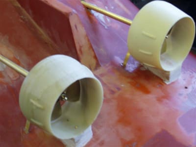
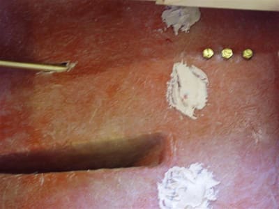
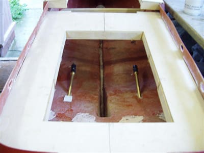
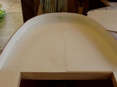
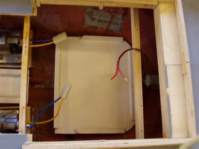
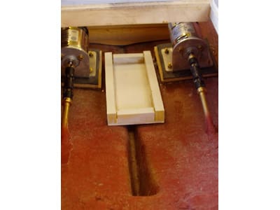
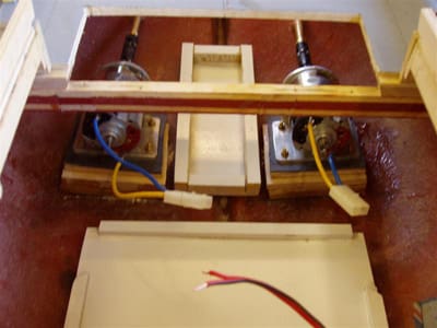
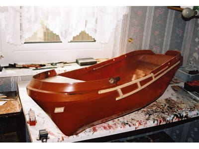
Pic 1 : Underside of hull showing Kort nozzles and propellers in place. Pic 2 : Close-up view of Kort nozzles and shafts. Pic 3 : Inside hull showing screws and securing material for nozzles, etc. Pic 4 : View of hull from stern showing propeller shafts in place. Pic 5 : Forward end of hull showing raised foredeck and styrene sheet covering. Pic 6: Detail of forward deck. Pic 7 : Midships view showing tray for two 12 volt lead acid batteries. Pic 8 : View of aft end of model showing tray for 6 volt lead acid battery and both main drive motors. Pic 9: Midships view showing main deck beam.
The rubbing strip locations together with those of the propeller shafts and rudder stock positions were added to the hull after it was sanded smooth. It should also be noted that the full size vessel has main drives through azimuth thrusters whereas the model is designed to use conventional propellers in fixed Kort nozzles. Among modellers there is some debate whether twin screws in steerable nozzles perform better than those with fixed nozzles and twin rudders – in my humble opinion the latter system is no different, performance wise, than the former and thus I plumped for the latter.
Enjoy more Model Boats Magazine reading in the monthly magazine.
Click here to subscribe & save.
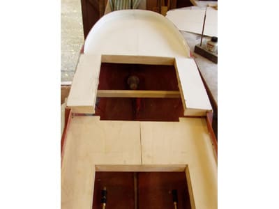
Planning
I must point out that this article is not intended to be a blow by blow account of building a model tug but a description of how the model was developed for production commercially. Often what is described is the result of a number of trials to determine the best way to build the tug easily. The photographs included do not necessarily follow the printed words but are included to give guidance to those who would build the model. When one builds a model either from scratch or when using a pre-made hull and appropriate drawings it is essential to plan each stage of construction carefully. For example one needs to plan what is to be installed in the hull, what motor(s) will be wanted, whether auxiliary services such as illuminated lights, smoke, sound, etc., are to be fitted, where the radio equipment and associated servos etc., are to be placed and so forth. I usually draw out a diagram showing the items that are to be installed and work out a scheme of wiring between them. Obviously this is modified as the construction progresses but such an exercise does ease the way in which the model building proceeds. If the model is built from a full kit then, obviously, full instructions will or should have been supplied and the method of construction can be very different from that described here. I find that, these days, fewer modellers venture into scratch building and I think that they often lose out on some of the pleasures of building. The joy one gains at seeing a model totally built by oneself sailing majestically for the first time is an experience not to be missed.
The hull
The grp hull I used was the first to come from the mould and needed a little attention to blemishes which would not have passed inspection in the normal run of business at Mobile Marine Models. Such blemishes were rectified and the hull was well washed with warm soapy water then rinsed and allowed to air dry. With such a large hull I considered it necessary to provide a sensible number of deck supports and beams to avoid any possibility of having the fibreglass shape becoming even slightly distorted.
There is, of course, a huge amount of space below the decks for fitting out the model and for installing the twin motor drive equipment and 12 volt sealed lead acid batteries needed to power the model. As mentioned the hull carries markings to show where sections of the bulwarks need to be cut away, where the rudder shafts will fit, where the propeller shafts will be sited and the location of the bow thruster, etc.
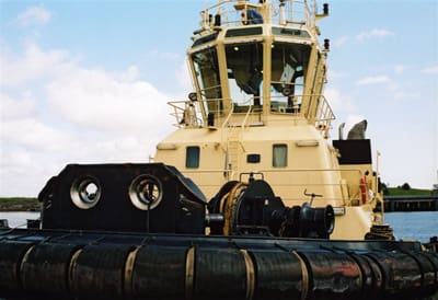
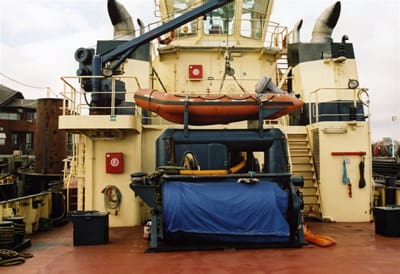
Pic 10 : View of hull showing preparation for rubbing strip rubber. Pic 11 : Picture of full size vessel from bow. Pic 12: View of superstructure of full size tug from stern. Pic 13: Upper superstructure of model showing strengthening bulkheads. Pic 14 : Main superstructure in primer with lower and upper sections joined together, note window shutters on lower unit.
Failure to clean the hull properly will almost certainly prevent paint from adhering to the surface in places and thus spoil the paint finish; once the hull has been cleaned it should be rinsed in clean water and allowed to dry naturally. It is also wise to examine the hull carefully and to mark any blemishes so that they can be rectified by filling or by rubbing away. The joint line that will almost always be obvious along the keel and from bow to stern should be gently sanded away and the whole hull should be lightly abraded with 400 or 600 grit abrasive paper to provide a good key for subsequent coats of paint.
In the case of this model no attempt was made to prime or undercoat the hull but it was checked for faults and the few places that needed filling were so treated before further work was done. All the openings round the bulwarks were cut away by first drilling round each marked place and then cutting each hole out using a fine saw and fine files; this needs to be done carefully as the gel coat of the hull can be quite brittle and break away during the cutting. It is best to apply masking tape over the area to be cut away as this will prevent the drill from wandering and keep the edge of the gel coat neat.
The locations for the rudder stocks were piloted using a small drill after they had been verified by measurement from the drawings.
Drive requirements
The full size vessel has twin azimuth thrusters at the stern and a thruster across the bow, and my lathe is not suitable for gear cutting or screw cutting so that I could not make suitable azimuthing units for the model. Therefore it was decided to fit twin propellers in fixed Kort nozzles driven from motors within the hull and shafts out to the props. Kort nozzles of 70mm (approximately 3ins inside diameter) were supplied by Mobile Marine Models, and matched left and right handed propellers were obtained from Prop Shop. The motors selected to drive these propellers and to provide a fairly high degree of thrust were 12-pole Buehler recommended by and purchased from Model Motors Direct to operate on a 12 volt D.C. supply and to give approximately 2,500rpm at full load so that gearboxes were not needed.
The Kort nozzles from Mobile Marine Models are very accurately cast in light plastic material and match the propellers from the Prop Shop well. To fit them to the hull and to allow then to sit correctly on the sloping bottom of the hull at the stern they were glued to blocks of 6.0mm thick ply that were then sanded to conform to the slope of the hull. The timbers were drilled and the material of the nozzles was tapped so that they could be attached to the hull firmly while they were glued in place using thick Superglue. Incidentally the 4BA screws used to hold the nozzles in place were left as additional security. The propellers were centred using a disc of ply made to fit the Kort nozzle exactly and drilled at the centre to accept the propeller shaft. The slots in the hull to accept the prop shafts were already marked in the grp when the hull was cast and only needed to be opened out. With each prop shaft centred in its nozzle it was supported in the hull with small packings of timber scraps while the outer shaft was sealed to the hull using catalysed resin. A pair of ‘A’ frames to support the outer ends of the propeller shafts were made from strip brass and tube and fixed in place through slots cut in the hull using more resin. Finally the fine brass propellers were fitted and happily ran truly in the nozzles, one being right handed and one left handed of course. Props on this vessel run outwards, i.e., the starboard prop runs clockwise and the port one anti-clockwise when viewed from the stern.
Rudders
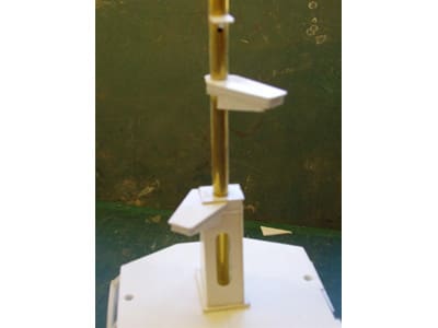
Once the nozzles were secured the rudders were each fashioned from two pieces of 3mm (1/8in) thick plywood. The ply was grooved in way of the rudder stocks and the two layers of ply sandwiched each rudder stock. Two part epoxy of the 24 hour type was used to glue the rudder halves and stock in place and added security was achieved by drilling through the timber and brass shaft to accept three small brass pins that were glued in place with Superglue. Once each rudder assembly was fully hardened the final shaping was carried out and both units were painted red oxide to match the underside of the hull. Extension pieces of brass strip to carry the bottom bearings for the rudders were shaped and fixed to the Kort nozzles using small brass countersunk screws of 6BA size (M3 is the metric equivalent) run into tapped holes in the material of the nozzles. Do note that BA and metric sizes are not interchangeable. I tend to use either one or the other depending upon what is available from the tool store in my workshop. Do note that the rudder sections were glued with 24 hour epoxy, the type that cures in five minutes is not suitable for use under water as it will degrade to jelly very quickly.
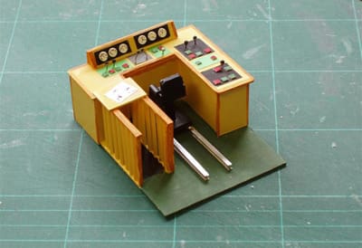
Pic 15 : View of wheelhouse under construction. Pic 16: View of wheelhouse to show end windows. Pic 17 : Control desk for wheelhouse complete apart from VDU units on main desk, the lever controls are made from map pins. Pic 18 : Wheelhouse partly assembled to illustrate base unit for main mast.
Pic 19 : Wheelhouse connected to main superstructure with unit being prepared for lighting cables. Pic 20 : Main mast under construction. Pic 21 : Front of main superstructure to show construction of guard and hand rails. Pic 22 : Forward tow rope guide unit almost ready to be installed.
Anchor boxes and bow thruster
The next tasks were to cut out the holes for and to fix in place two fairly deep anchor boxes near the bow of the model – these being already marked upon the hull. The anchor boxes themselves were made from 2mm thick styrene sheet and fixed in place using Superglue and catalysed resin. I prefer catalysed polyester resin for fixing parts into grp hulls as it is the same material from which the hulls are made and is therefore compatible, giving a very sound and almost indestructible joint. The holes for the anchor stocks and hawse pipes will be made when the decks are completed and the windlasses can be sighted.
Final work upon the hull at this time was the fitting of the bow thruster pipe and unit; the bow thruster selected is from the Robbe range and is of the paddle type where a two-bladed paddle revolves in the top of a cross tube to move water one way or another. It is of good value and well made and the cross tube supplied is almost of the same diameter as the full size unit would be when scaled down.
It takes a little care and some preparation to accurately cut the oval holes in the sloping hull sides to accept the thruster tubes but, having previously made a few, one needs only to remember how and be careful. 1 can’t think of a simple way of cutting this hole in each side of the hull, in this instance a short piece of wooden broom shank was cut and sanded to the correct angle of the hull when it was truly horizontal and used to mark off the oval shape needed. Some filing and sanding was still necessary to allow the actual sections of tube to be slid into place after which the thruster unit was fully assembled and fitted. It was sealed to the hull using Stabilit Express – the recommended glue – and the outer ends of the tubes were cut away and sanded flush with the hull. The bow thruster is rated at 6 volts so that it will be fed from a separate battery system to the main drive motors that are 12 volt units.
Deck beams
Strips of 3.0mm (1/8in) thick ply by 10mm (3/8in) wide were next attached to the inside walls of the hull to support the outer edges of the main decks both forward and aft. There is no marking on the hull for this other than the relief slots that have already been cut and the deck needs to fit flush to the bottom of these slots. The main decks were to be made from 3.0mm thick marine ply so that the perimeter strips were set at 3.0mm below the lower edges of the slots. The strips were tacked in places with Superglue and sealed with catalysed resin after which a second strip was glued over the secured one to give a 6.0mm (1/4in) wide platform for the deck. The cross deck beams were next prepared from 6.0mm thick birch faced plywood; those for the stern area being cut to 22mm wide and parallel while those for the forward deck were cut to give a camber curve to the deck 6.0mm higher in the centre than at the sides. The beams were set at centres approximately 100mm (4ins) apart and glued with PVA with additional supports of triangles of scrap ply at each end. The whole beam assembly was left for 24 hours for the glue to cure before any further work was attempted.
Decking
Card salvaged from cereal packets was next used to make templates from which to cut the main decks, it is much easier to get an accurately fitting deck if card is first used and shaped to conform to the curves of the hull. It was decided to make the main decks in four pieces, two for the bow deck and two for the stern and allow them to join down a centre line, in this way pieces of 3.0mm plywood bought in standard widths of 12ins could be used and I had no need to travel very far for such material; to obtain wider sections would have needed a 50 mile each way journey. The decks were glued to the beams with PVA glue and tacked down with small brass pins for added security. Finally the main decks were covered in 0.5mm thick styrene sheet glued in place using a contact adhesive; this was done for two reasons. First the styrene obviates the need to fill the grain of the ply and rub it down to simulate the smoothness of steel and second it also allows other styrene parts to he easily fitted and secured. Once the decks had been treated, the inside of the bulwarks were rubbed down and also given an inner covering of 0.5mm styrene secured by contact adhesive.
Small triangles of styrene sheet of 1.0mm thickness were cut and glued in place with liquid polystyrene to simulate the bulwark supports and once this was dry and all the supports were secure, the inside of the bulwarks were spray painted medium buff. Finally the top rail of 1.0mm thick styrene was cut to suit the bulwark curves and glued down using Superglue.
First painting
At this point the hull was cleaned and given five coats of red oxide primer from spray cans; each coat was allowed to dry and was lightly rubbed down with 600 grit abrasive paper before the next was applied. Having allowed the red oxide 48 hours to cure the hull was set up on the work bench and the water line was marked off by reference to the drawings using a soft pencil attached to a large square drawn round the hull once the waterline was brought parallel to the bench. The lower hull was masked off using fine plastic masking tape followed by paper masking tape to hold dry newsprint over the whole lower hull. The decks were also masked and tape was applied over the inside of the hull cut out sections to ensure that a minimum amount of overspray would need to be dealt with. The upper hull including the top rails of the bulwarks was given five fine coats of matt black from automotive spray cans and was treated in the same way as was the red oxide. The hull was then set aside for seven days to allow the paint to become fairly firm. The paint used for both colours came from the Halford’s range of primers.
Ballast check
Before proceeding much further the hull was placed in the domestic bath and weighted to bring it close to the waterline – a total of 46 pounds was needed comprising two 12 volt lead acid batteries, one 6 volt battery and some 25 pounds of lead sheet of 1/8in thickness. The water test being satisfactory the main drive motors were fitted on trays made to suit them and secured into the hull using catalysed resin.
Superstructure
We have reached the point where a start could be made on building the superstructure. Here consideration had to be made regarding the location of a suitable battery pack to feed the many lights and also to allow for the running of the small wires that were to feed the lights. All the lights were, in fact, located on the superstructure or on the masts above and thus, by installing switches and having the battery pack for the lights within the structure it is possible to have it detachable in one piece. Careful examination of the drawings and photographs of the tug showed that a 9.2 volt NiCad battery pack could be safely fitted into a tray in the lower after section of the deckhouse where it would be clear of the electrics for the main drive equipment. The lights to be fitted are rated at 12 volts and by supplying them at only 9.2 volts the life of each lamp is very much extended so that replacement – always very difficult – is avoided during the reasonable life of the working model. The lights on the model will rarely be illuminated for more than 15 to 20 hours per annum – how many modellers sail in the darkness very often?
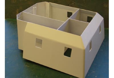
Deckhouse unit
Templates for the lower section of the deckhouse unit were made from the main drawings and used to relate the lower deckhouse to the model. The lower unit is made almost totally of 2.0mm thick styrene sheet except along both port and starboard sides where 1.5mm styrene is used. The lowest lights of the model are on the funnels of the tug and on either side (port and starboard) just above the top of the lower unit, holes were left through which the lighting cables could be fed as the structure was assembled.
There are only a few windows in the sides of this unit and all the windows have steel covers that can cover the glazing when the tug encounters heavy weather. Note that such steel covering doors and access doors into the structure are hinged so that they close towards the stern, i.e., doors on the starboard side have their hinges on the forward edge (right hand side) while those on the port side also have their hinges on the forward edge (left hand side). This is so that loose covers and doors will always tend to close naturally when the vessel is moving into a storm. The window openings in the whole superstructure were left un-glazed until all the painting was completed and, of course, access to apply the glazing was made available as the work proceeded. From this one can see that careful measurement and thought is needed before any material is cut and fitted.
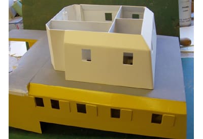
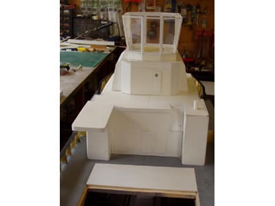
The section of deckhouse that sits above the lower unit is much smaller and it was also built as a separate self-contained unit that was detailed and painted before being attached to the lower section. It too, was made from 2.0 and 1.5mm styrene sheet using templates cut from card as guides to correct cutting out and fitting. As there are a number of reasonably sized windows in both of these units it was deemed sensible to install division walls so that it would not be possible to see through from one side to the other. A styrene tube was also installed between the top of the lower unit and the top of the upper unit through which to pass the lighting cables. This section of the deckhouse was the easiest to make as, apart from the windows there is only one door in it.
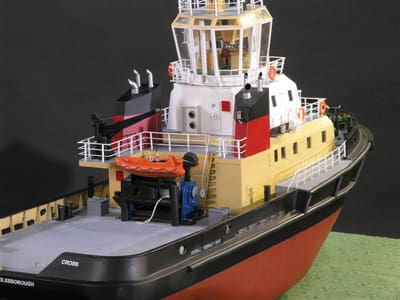
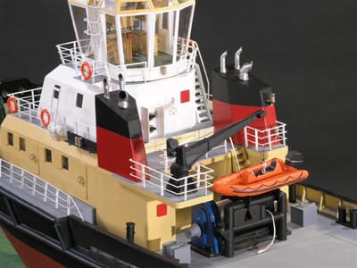
The lower unit has three doors in the stern bulkhead and it also carries the upper deck extension on which the crane, used to handle the RIB, sits. The twin funnels are carried on the after part of the top of the lower structure, the starboard funnel carrying two white navigation lights. On this model these funnels were fabricated from styrene sheet but they will be available as complete units in hard cast plastic from Mobile Marine Models when the fittings outfit is completed by them.
Wheelhouse
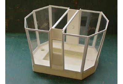
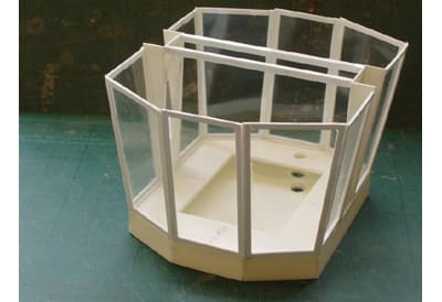
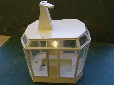
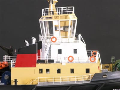
By far the most time consuming and difficult task of the entire construction was the wheelhouse. As can be seen from the photographs it is of almost totally glass construction and called the ‘greenhouse’ by the crew.
After a great deal of thought and some experimentation it was finally built by first assembling the base unit complete with its fore and aft lights and then building up each large glass section from styrene strip and 15 thou thick Evergreen clear styrene using a template for each section to ensure that all would fit properly. Easier to describe than build – the task took a long time.
The topmost windows were also made from styrene strip and Evergreen clear styrene and, again card templates were made first to ensure a good fit. A styrene tube was also placed between base and roof level to carry the lighting wires for the masts on the roof. Note the stress upon styrene and particularly clear styrene sheet from Evergreen, this is because, clear styrene from Evergreen and white styrene strip from the same source can easily be sealed and joined using liquid poly. Provided that no liquid is allowed to run on to the clear area a firm and satisfactory joint will result. The clear plastic sheet sold by most model shops is not of the same material as is the Evergreen and liquid poly will haze this even when used with care.
At this point a roof was cut from 2.0mm styrene sheet and trimmed to fit the wheelhouse but it was not fitted at this time. With complete visibility into the wheelhouse it, of necessity, had to be fitted out inside with control desk, helmsman’s chair, VDU units and instruments and the banister rails that surrounded the stairs down to the floor beneath. This desk, chair and banister rails were built from various pieces of plastic and wood and assembled upon a floor of 1.5mm styrene sheet painted green and large enough to cover the base of the wheelhouse and hide the lighting cables within the base unit. Finally the wheelhouse was painted white with the upper window frames in buff using two very fine watercolour brushes and acrylic paints.
The roof of the wheelhouse carries the main mast and two small masts each having three lamps – one on each side and there is also the master binnacle; the whole roof being surrounded with guard rails. On the underside of the roof there is a downward projecting unit in two sections carrying, I believe, the air conditioning equipment and some instrumentation. This pair of units was made from 1.0mm thick styrene, painted to match the deck and fitted with grilles and suggestions of instruments as it too is visible clearly through the wheelhouse windows.
The roof was made from 2.0mm thick styrene in two layers, the upper layer to lie over the edges of the wheelhouse sides and the lower to fit neatly inside the wheelhouse to create a substantial base on which to built the main mast and auxiliary masts.
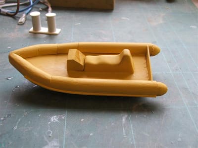
Pic 23 : Completed fore deck with single post bollards and access hatches in place. Pic 24 : Model of the rigid inflatable boat under construction and in primer. Pic 25 : R.I.B. complete and lacking only safety ropes and outboard motor unit. Pic 26 : Starboard view of completed superstructure. Pic 27 : Aft starboard quarter view of completed model. Pic 28 : View of model from port stern quarter to illustrate mounting of R.I.B, crane and funnels; lighting switches are visible to the right of the port funnel.
Masts and lamps
The auxiliary masts are simply lengths of styrene tube through which the cables for the lamps are fed and to which the lamp brackets – also of styrene sheet – are attached at the correct spacing. Each mast has three lamps reading red over white over red. In full size practice each lamp has two all round lenses one above the other, the upper lamp of each being fed from the main lighting system of the tug and the lower fed from a battery back-up system. On the model only one bulb is fitted to each lamp although it is actually sized as two lamps at each point. The bulbs used are ‘grain of rice’ 12 volt units clear or coloured as required and obtained from a mail order outlet called Squires at Bognor Regis. Each of the two auxiliary masts are fitted into carefully sized and drilled holes through the roof of the house and each lamp has a backing board painted black as can be seen in the pictures.
The main mast is quite complex and carries six lamps, three facing forward mounted on brackets on the main tube and three facing aft mounted on a tube carried on the safety rings of the ladder on the aft side of the main tube. There are also two platforms carrying radar scanners, a signal lamp on the mast top and a number of bi-pole aerial units mounted on brackets attached to the main tube.
The main central tube of the mast on the model is made of 5/16in brass tube running through a mounting unit made of styrene to match the drawings and terminating just through the roof of the wheelhouse.
The three forward lights, red over white over red, are fixed to styrene brackets glued to the brass with Superglue, the wires from the bulbs run into the inside of the tube through small holes beneath each bracket. Attached to the aft side of the main tube is a ladder of plastic from the Plastruct range and fixed to the brass tube with small rings of brass wire secured with Superglue. To this ladder is fitted a series of safety loops with a brass tube of 1/8in bore glued to the aft of each loop with Superglue and with two small wires running down port and starboard sides – the whole forming the safety cage system.
Use was made of this design to feed cables to the lamps mounted on brackets attached to the small bore tube, one wire from each lamp was soldered to the tube to form the return for the current and the other three wires were led, one inside the tube and one down each side of the cage, the lamps were red over white over red as for the forward facing lights. The single signal light on top of the mast was not rigged to light up as it would, in full size practice, be very rarely used in these days.
Finally the platforms for the radar scanners were made from styrene sheet and attached to the mast using Superglue.
The Bi-pole units were made from scraps of fine wire, styrene and tube and attached to the mast with the ubiquitous Superglue – what would we do without it? Finally the whole assembly was very gently washed in warm soapy water and air dried, the wires were grouped together and the lamps were tested, the lamps were then covered with scraps of plastic tube and the whole mast was painted first with a couple of coats of primer followed by four fine coats of buff colour to match the lower deckhouse and wheelhouse top.
Described in these few paragraphs the main mast, auxiliary masts and wheelhouse has occupied just over 100 man hours, possibly a second run would halve this figure as all the bugs have been ironed out – I think.
Once the paint had dried thoroughly the roof with masts was glued to the wheelhouse top, two pairs of hands being needed, one to coax the 12 or so small wires through the tube to the base of the unit and the other to guide the roof to its home; once in place the assembly was glued down and set aside for some days to dry out.
Assembly
At this point the three sections of the superstructure were brought together and glued firmly using liquid poly, the grey paint of the decks was touched up as necessary and the joints between sides and decks sealed with thin pieces of styrene rod. Once completed and left for a few days, the structure was found to be extremely strong.
The wires from the various lamps were brought together into two circuits – one covering those lamps needed for navigation and to comply with the Classification Societies’ Rules and the second covering the Christmas tree of red and white lamps used to indicate the work being carried out by the tug when working. Both circuits are fed from the same 9.2 volt battery but are separately switched with watertight switches located in the aft wall of the boat deck accommodation unit.
It was noticed that the drawings and photographs both showed that there were two pairs of lamps at each side position –port and starboard – and that the side boards did not have an end board fitted. A query to the chief engineer of the towing company revealed that at both side positions there are two pairs of lamps, one pair coloured green and one pair red. On the starboard side the lamp facing forward is green and the stern facing one is red while this is reversed on the port side. The reason for this is due to the nature of towing as this tug and her sisters spend almost as much time towing when running astern as when running ahead and when they are running astern the side lights can show the correct aspect.
Guard rails
These created something of a problem as there were no readily available flat bar stanchions in brass at the scale of 1:32 commercially and the costs in time and production negated any chance of making such units in house so that consideration was given to using stanchions cast in white metal by Mobile Marine Models. They were very slightly under the required height and attractive as we needed some 100 to cover the railed area of the model. In fact they were used to make up the guard rails on either side of the main deck in conjunction with some silver coated copper wire. In a straight run they were satisfactory but when it came to making up rails with curved ends and corners the adhesive (Superglue – full strength thick) failed to hold the top rail into its grooves. Thus all the rails of the superstructure proper were made from styrene; 1.0mm thick x 4.0mm wide strips were used for the stanchions and two sizes of styrene rod (1.6mm and 1.2mm) were used for the horizontal rails. A small jig was made to allow of accurate drilling of the flat strip and the stanchions were made in pairs so that the central large bore hole formed the top of each stanchion when sliced into two parts. Provided that an adequate amount of time was allowed for the liquid poly to dry at each joint the resultant guard rails were remarkably strong and resilient. It is being recommended that Mobile Marine Models has stanchions etched from brass sheet so that guard rails for the models in the future will have the benefit of stronger rails that are soft soldered together. One advantage of the styrene rails is that they require no painting to show white rails.
Main Drive Equipment, etc.
Before too much time was spent upon finishing the model the main drive equipment and radio controls were next installed fully and given a thorough testing. In the test tank (domestic bath) ballast was added loosely until the hull lay close to the waterline and the main motors were run up. The bow thruster was also given a test and performed as expected.
The cross hull pattern bow thruster is, of course, ineffective when the model is running ahead or astern as the speed of water across the openings in the hull prevents the thruster from being fully effective – this is also the case, I am told, in full size practice. With the main motors stopped the bow thrust will swing the model easily in either direction. A spring balance was used to assess the bollard pull and gave a surprising loading of 5.6 pounds.
The ‘basin trials’ lasted around an hour and then the model was dried off and the large lumps of lead used as temporary ballast were weighed and cut into the required sizes for permanent installation, the total deadweight of the model turning the scales at 46lbs. All the lead ballast was in the form of sheet about 1/8in (3.0mm) thick. It was cut into appropriate sizes and fitted, not only into the bottom of the hull but also well up the sides so that the hull would roll realistically. Weight placed over the keel alone of a model will generally make the model too stiff and unrealistic when on the water, however, there are exceptions to this rule as there are to many others, for example, when a model is tender, or tending to roll too easily to a point of capsizing then ballast is needed as low in the hull as possible. With Ayton Cross having a very wide beam there is almost no chance of a capsize even in very heavy seas and the model performs in the same manner.
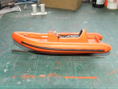
R.I.B. and Crane
Mounted upon a cradle on top of the stern guide unit is a rigid inflatable boat, used as a workboat and also serving as a lifeboat. This was made from timber dowel and 0.8mm thick plywood. The dowel was cut in half lengthwise and then into a number of small pieces to form the inflated portions of the boat, the slight curve towards the bow was formed by cutting part way through the main plywood base and then shaping the small pieces of dowel to hold the shape. It was sealed and sanded before receiving three coats of ‘dayglow’ orange acrylic paint.
The control position was formed from pieces of thin styrene and fitted with a cast wheel; finally the rubbing strips and safety guy ropes were fitted. The model was sprayed with matt varnish before being glued to the mounting with superglue. The crane was made from a Mobile Marine Models kit modified to suit the drawings and photographs of the full size vessel and when finished in black was positioned over the R.I.B. but not connected to it to allow the superstructure to be removed easily.
Finishing
As will be seen from the photographs, Ayton Cross has an almost totally unobstructed stern deck so that the large hatch needed for access has almost nothing in the way of coamings to prevent water from entering the hull. The hatch does land on a timber surround and to give added security some of the lead sheet was glued to the underside of the hatch cover; this makes removal a little difficult but will aid in keeping any water that gets on the deck from entering the hull.
Small hatches – five in number – were made from sheet styrene and painted before being glued in their respective locations, the small hand wheels on each hatch top came with many other small parts from the stocks of Mobile Marine Models.
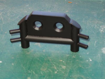
The very large rope guide units at bow and on the stern deck were made from styrene tube and sheet to scale from the drawings provided. The unit at the bow was fitted with short lengths of timber dowel in the vertical tube legs and glued through two holes in the foredeck using two part epoxy. The unit aft of the main towing winch on the stern deck was made much more strongly having timber dowel glued into the vertical legs right to the top of each tube; the dowel leg extensions were carried right down to the keel of the model and secured with catalysed resin so that the unit can be used for towing without coming apart.
Winches
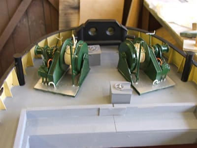
The main towing winch with its twin towing drums was constructed using some cast white metal and resin parts from Mobile Marine married to parts made from styrene and brass. It was made to match the drawings and photographs, painted blue and black and finally fitted with suitable cord to simulate tow ropes. It was not only glued to the deck ahead of the tow rope guide but also bolted down using 6BA brass bolts and nuts through the deck.
The twin winch/windlass units on the foredeck were also made using many Mobile Marine parts but the frames and shafts, etc., were made in the workshop. These units were painted green but also have some pipes and parts in colours. These combined units also have tow ropes upon their winch drums and chain cables over the gypsies from the hawse pipe tops and down to the chain locker. The strange tall pipes with cages at the top are, in fact, the hydraulic rams that control the brakes of the main shafts, in full size these need to be very powerful.
Final jobs
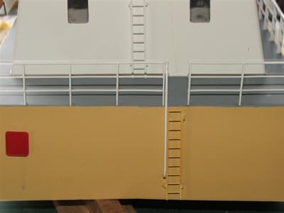
The final work on the hull involved fixing rubber bumper strips to match those of the full size vessel. On the sides this was carried out using ‘D’ shaped rubber from the Robbe range fixed to the marked places on the hull with thin Superglue. At the bow a number of runs of 10mm x 6mm (3/8 x 1/4in) flat rubber were applied to build up the required depth and shape. Two large twin head bollards are located on either side of the main hull just aft of the break, the heads were turned from a length of 12mm diameter plastic knitting needle glued to a base of 3.0mm (1/8in) timber and capped with discs of styrene. The single post bollards were made from 10mm diameter knitting needle plastic, cut to length, fitted with brass rod cross bars and capped with discs of styrene. The bollards were all painted black by brush before being attached to the hull with Superglue.
Eventually and after carefully checking that all had been done and fitted in accordance with the lists, the model was examined for faults. Small areas of the hull were rubbed down and repainted where damage had occurred; other places were also touched up using a fine sable brush and appropriate colour.
The model was carefully cleaned and rendered free of dust then the hull was given three coats of matt varnish, the superstructure had been varnished before the glazing was fitted.
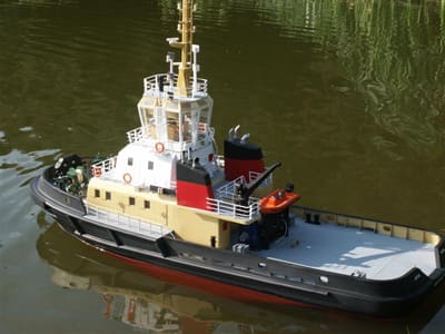
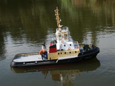
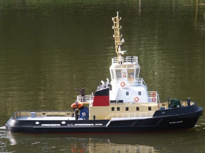
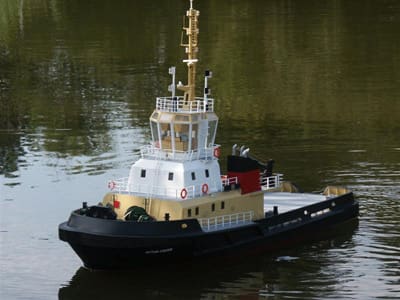
Pics 29-32: Completed.
The day came for a test on the lake and a photographic session too, both were deemed satisfactory and the model was finally collected by a pleased and happy client.


