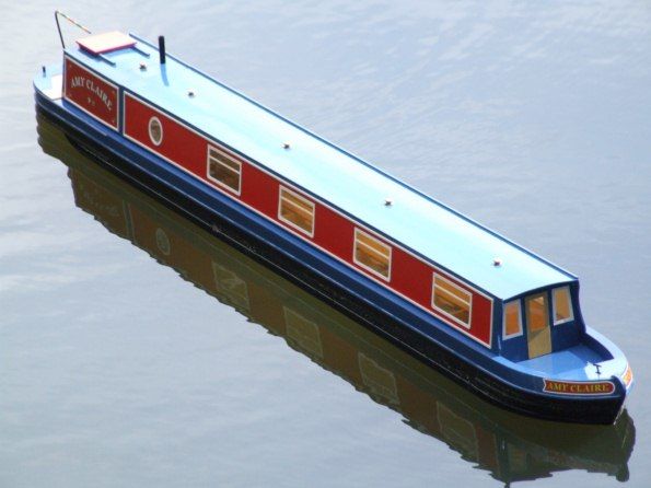
Amy Claire
DAVE BRUMSTEAD reviews the Riverside Models Narrow Boat Kit
Enjoy more Model Boats Magazine reading in the monthly magazine.
Click here to subscribe & save.
This kit is supplied well packed in a flat cardboard box approx. 50 x 15 x 3 inches. The contents include: A comprehensive step by step set of instructions, parts list, parts location diagrams, a set of constructional diagrams, a CD with colour build sequence images, sheets of routed parts, stripwood, window frames and window glazing, motor and mount, running gear and a purpose made rudder and tiller. Some of these can be seen in Photo 1 with the instructions and decals in Photo 2 and the smaller parts and accessory packs in Photo 3.
Hull construction
After reading through the instructions the routed parts were identified, Photo 4, and before removing from the sheet, the part numbers were pencilled on to each of them. A modeller’s fine cut saw, rather than a Stanley knife, was the best way of removing the parts. Once removed from the sheets, their edges were cleaned up on a Minicraft sander.
The first task was to build the bow section of the model. Following the information in the instructions, the formers of the bow section were chamfered as in Photo 5. It is important to get this right so the bow skinning and planking will have the maximum contact surfaces. An adjustable bevel gauge and a protractor help achieve the correct angles.
These bow section components were assembled dry and when I was happy with the fit and the angles on the frames, the assembly was glued together with Deluxe Materials Aliphatic resin adhesive, Photo 6. This was all straightforward work and it was immediately clear that Riverside Models have gone to much trouble to get the kit development just right.
The main centre section of the hull was built next and in the instructions the schematic figure shows the gap between all the bulkheads to be 93mm, with just one exception. To simplify and speed the construction process, I made up four spacers from 15 x 15mm square section scrap wood, which would enable two frames to be glued at a time to the hull centre section 6mm by 6mm stringers, Photo 7. The frames must be spaced correctly and vertical to the building board. Note that the bottom skin is not being used at the moment. Once the glue had set, the side and top stringers were glued in place, again ensuring the assembly was square, Photo 8. A piece of flat melamine shelving is as good as anything for the baseboard.
The next step was to assemble the stern of the model. The bottom base section was laid on the bench and the hull rearmost frame glued in place at its front, once again ensuring it was upright, Photo 9. Marking the centreline on the base section will later help when aligning the propshaft.
The positions for the spruce side supports were also marked on to the base using dimensions from the drawings. The 40mm long spruce propshaft support (supplied pre-drilled) is glued in place at the rear of this bottom piece and using the propshaft as a temporary template helps.
The hull side spruce supports were now glued in position, Photo 10, ensuing they were upright, plus the tapered propshaft support, ensuring the taper ran in the right direction!
The stern middle piece was now made up and glued in place on top of the supports just previously fitted, after drilling it for the 9mm rudder tube, Photo 11. Please note that the position for this was altered from the 53mm spacing stated in Figure 4 of the instructions to 50mm. The 38mm long spruce supports for the top section (actually the deck) were now glued in place. The top deck hatch supports were also glued in place and once dry, the top deck fitted after the rudder hole had been drilled in its new position, which is 46mm from the hatch instead of 49mm, thus aligning with the rudder hole in the middle deck. The hole in the deck though, is only 5mm in diameter, Photo 12. A pre-drilled balsa part was glued in place over the propshaft and when dry, shaped to the profile of the stern and the rudder tube was then also fitted.
The centre section of the hull now had its bottom skin glued in place to the stringers and frames. This is deliberately supplied slightly too big and requires a small amount of sanding to finish to size.
The attachment pieces for the stern section were now fitted to the main hull, Photo 13. These, with additional wooden clips hold the stern and main hull together. It is a sort of slot and tab method with the stern section hooking into these shaped wood sections and retained by wooden clips as seen on the stern deck in Photo 14. This is all rather clever and a very positive way of joining the stern unit to the hull centre section.
The next step was to skin the bottom of the stern, Photo 15. Once dry the skins were trimmed and the hole for the propshaft opened up which was glued in place on its support with Deluxe Materials 20 minute Speed Epoxy. This glue allows sufficient time for minor adjustments before setting, Photo 16.
The motor was fitted to its mount and offered into place and a problem arose as the motor and the propshaft were not in proper alignment, Photo 17. This was the first minor hitch in what had been a perfect job thus far. It was not possible to reduce the height of the mounting, so I substituted a metal version from stock. Even this needed modifying to clear the central keel and it was fitted using bolts into blind nuts to 3mm ply plates, glued each side of the keel, Photos 18 and 19. In fairness to Riverside Models, this was a first production run kit and the manufacturer has I understand now rectified the problem in subsequent kit output.
The rest of the stern was now skinned and the after hatch parts assembled. With the hatch in place, the rear deck was offered into position with a double thickness of masking tape underneath. Once happy with its position, a screwdriver of the same diameter as the rudder shaft was pushed up from the bottom, indenting the masking tape which gave the position for the hole for the rudder shaft to be drilled, Photo 20. This deck was now glued in place over the top of the stern section.
Bow section and skinning centre section
The previously assembled bow section was now fitted to the central hull section, using the same techniques as for fitting the stern unit and once the glue had dried, the main side skins were glued to the main body of the hull. These are also supplied slightly oversize, so will need to be lightly sanded to shape.
With their positions marked on the frames at the bow, two 1.5 x 3mm strips were glued in place. These are the dividing line between the upper and lower bow shapes, Photo 21.
Two templates are provided in the routed sheets for the upper and lower bow section skinning, which because of the complex curves is planked. The template shapes need to be transferred to 1.5mm balsa sheet and these then cut out, Photo 22, as these provide support for the bow planking. This is a good idea, as the balsa can flex quite easily in two planes, providing a positive backing for the 1.5 x 3mm obechi planks. Photo 23 shows the balsa supports in place and planking in progress. Note how the upper section has the planks running bow to stern and the lower section has them being placed diagonally. This makes the task very simple with no complicated bending required. Once complete, the flat bottom of the bow unit had the excess planking sanded away and its bottom skin glued in place, Photo 24. The instructions advise that it is a good idea to coat the inside of bow with GRP resin or similar to strengthen the planking. I opted to use Eze-Kote as it dries quickly and can be cleaned away with water, Photo 25. The bow top deck and remaining parts were now glued in place to finish it all off, Photo 26.
The framework for the inside area of the main hull was made up from balsa and glued in place. This supports the internal side (cabin) walls and floor. Once the these cabin side walls were glued in place, the outer side decking could be glued to the hull and these supports and then sanded flush to the outer skins.
The floor was offered into position and trimmed as required. It is meant to be an interference fit, so I was concerned that if it was pressed into place it wouldn’t be possible to extract it as ballast will be needed and that will fit in place between the cabin floor and hull bottom. So, a blind nut and bolt or something similar is handy to enable it to be easily removed from the hull.
R/C mountings
There are three ‘mini- kits’ included for the battery tray, accessory tray and servo mount. The servo mount is made up first as in Photo 27. A couple of strips of scrap wood underneath give the servo mounting screws something more to grip. This unit was then glued into place as shown in the instructions.
The accessory tray is a simple platform to accommodate the receiver and speed controller etc. It simply slides into place, dropping down into its location where it is held quite firmly, but can still be removed if required. Finally, the battery tray is designed to fit over the motor and can hold a standard 6v 4.5 Amp SLA (Sealed Lead Acid) battery, Photo 28.
Main cabin top sections
These comes next and the cabin is in two sections for convenience. Each is assembled in much the same way by gluing their end walls and supporting frames to one side, followed by the other as in Photo 29. Be careful to get them all square and with no twisting and allow the glue to properly harden. Roof beams need to be added which are sanded so their profiles matched the curvature of the roof. Lots of clamps and tape will then hold the roof in place whilst the glue sets. The rear smaller cabin unit was made in the same way, but it does taper slightly towards the stern. When test fitted to the hull, a piece of paper between the two sections ensures clearance to allow for the thickness of paint later as in Photo 30. Roof rails were added for a sliding hatch, to the rear cabin section after its roof was trimmed to shape, Photo 31.
Detail work
At this stage, according to the instructions, the cabin and main superstructure doors should be fitted. However, I think it is easier if these, as well as the hatch, windows and side trims were left off until after painting the main cabin body. So, I pressed on with making up the rudder linkage etc.
The pushrod from the tiller arm to the was approx. 7 to 8mm too long. Better too long than too short! This was easily rectified and the tiller fitted to the rudder shaft and then connected to the servo as in Photo 32. The rudder support skeg was also fitted to the underside of the hull and located into the bottom of the rudder. I think this may be rather vulnerable under the long flat bottomed hull, so two scrap pieces of 5 mm square wood were glued either side of it for protection and extra strength. If you wish, you can also now finally install and connect the motor to its propshaft with the provided coupling.
Rubbing strakes need to be added to the bows, but before then the Obechi planking was covered with wing covering cloth and Eze-Kote for additional strength and to achieve a good finish, Photo 33.
The plastic rubbing strakes could be gently curved in the fingers and applied to the hull with medium superglue and accelerator, Photo 34. After the first strake had been fitted, dividers were used to mark out the correct position for the second and third strakes and there is a similar arrangement at the stern.
Painting
After the usual basic preparation for wooden models, namely sanding to a good finish and removing dust etc., the model was primed with a few coats of ordinary household white primer, rubbing down between each. For the top coats, a household spirit based non-drip gloss paint was used for both the red and blue. For the matt black underwater section, gloss black was used and then oversprayed with Ronseal matt varnish. All of the painting was done by brush with only the varnish being sprayed. The window frames, Photo 35, were painted white when off the model and whilst still in their carrier frames. Photo 36 shows painting in progress on the cabin.
The trim strips were glued in place with R/C Modellers Glue, which has the advantage of allowing a small amount of movement for alignment and it also dries clear. One line of trim was glued in place along a straight edge and the opposite trim was fitted using spacers from the previously glued trim. This ensured an even, straight trimline, Photo 37. A spacer of the correct width was also used to position the window frames, ensuring they were central to the apertures, Photo 38. Once the glue had dried, the glazing which is also routed to the correct shapes and sizes, was glued in place with R/C Modellers Glue.
Small fittings
There are not many of these and the instructions give the correct locations. The resin cast roof vents were easily assembled and painted a brass colour with a Humbrol enamel. The rear cabin chimney had to be filed on its base to ensure it was vertical when fitted to the profiled roof and it was held in place with a brass locating pin, as were all the roof vents and the rear top hatch, Photo 39. The supplied hull nameplates were also fitted and the tiller was painted in the fashion of canal boats, Photo 40, and fitted to the protruding rudder shaft.
Radio control
All that remained, except for ballasting, was the installation of the radio control equipment, Photo 41. An Electronize esc and Multiplex r/c system were to hand and therefore used and these, together with the receiver battery, were fixed onto the accessory tray using Velcro with a separate mount for the adjacent on/off switch. A 6v 4.5ah SLA battery was installed in the battery tray and the receiver aerial run into the main cabin area and taped along its inside.
On the water
With the cabin floor removed, approx. 9lb (4kg) of lead ingots were placed between the frames and the keel until the model looked about right on the water. Each piece was then labelled with its hull position, ensuring that they could be removed and replaced at will. Don’t forget that this model is getting on for nearly 6ft long and that’s not easy to transport, particularly if fully ballasted as well. On the water the model performs rather like a real narrow boat, which is hardly a surprise. There was some propeller cavitation and rapid movements astern were definitely not on the agenda. A propeller with more pitch may well go some way to solving this, but it is a pleasant model to sail and does what it says on the box.
Conclusion
The detailed instructions are superb and an example to other manufacturers. The construction photos, building CD, A3 sheets of construction information with all the dimensions, part locations and listings are quite remarkable. This all wooden kit is accurately routed and the vast majority of these parts (all of good quality wood) just push together. So this was an enjoyable kit to build and the only area I got bogged down with was obtaining a dust free finish when painting it. The manufacturer was made aware of the problem with the motor mount and the need for a better propeller which has been rectified. No internal cabin detail is included, so there is plenty of scope for the builder to fit his or her model out in whatever style appeals. There are plenty of doll’s house accessories to compliment such interior work.
Kit particulars
This is a 1:12 scale narrow boat kit producing a model 66 inches long by 6.75 inches beam and of wood construction. The kit comes supplied with all necessary timber which is CNC precut from quality plywood and the windows and their frames are laser cut. Also included are the rudder and its linkage, tiller arm, skeg, propshaft, propeller, coupling, a Graupner 500 Eco motor and mount. Fittings include resin cast roof vents and bollards, plus other white metal parts, decal sheets and comprehensive building instructions and drawings with a CD. Price is £279.99p plus p&p from Riverside Models, Bluebell Cottage, Whimpwell Street, Happisburgh, Norfolk, NR12 0QD, tel: 01692 652960, website: www.riversidemodels.co.uk, or email: [email protected]


