The free plan to a scale of 1:20, drawn by James Pottinger in the October 2004 issue of Model Boats provided me with an opportunity to build a model boat that had an appealing shape, ought to be simple to build and within my ability. The 45ft Admiralty MFV was a type of service craft of which over 300 were built during WWII.
Model development
As a first-timer to the modelling of a scratch built powered model boat, I wanted to develop the required dimensions, plan how to construct the boat, make allowances for the motor, batteries and r/c within the hull and decide exactly how I wanted the model to be finally completed, since there are numerous options with these craft. In keeping with the style of trawler, I decided to adopt the plank on frame method of construction, so that the hull would indeed have the finished characteristics of a planked hull.
Using the plan, the only baselines from which precise dimensions could be obtained, were the horizontal waterlines (especially numbers one and five), the centreline, stations (frame spacing) and a horizontal baseline which was established through station 0.5, which is the start of the keel. These baselines were used to develop a table of dimensions to establish the exact profile of the hull, bow, stern, deck and the keel. An interesting feature of this boat is that the keel rises from the stern to the bows, hence cannot be used as a baseline. The dimension tables I created by measuring from the centreline and along a waterline, were used to set out the profile of the hull. For example: Using station three and waterline three on the plan, the half breadth to be measured each side of the centreline along waterline three is 113mm. Pencil marks are made for all of the measurements which are then joined by a freehand line to provide the shape of the hull at a particular station (or frame). This process was applied at all the stations to set out the hull profile.
Enjoy more Model Boats Magazine reading in the monthly magazine.
Click here to subscribe & save.
In a similar manner, offset dimensions were established for the stern and bow. Measuring off the plan from a new station (-1.0), a series of dimensions were determined along each waterline. Some extra waterlines and sections were drawn in these areas to more accurately determine the rabbet line, the stern profile at the propeller/rudder area and deck. The bows is also divided into additional waterlines from station nine to construct dimensions along each waterline and the intersection with the bow shape.
Hand drawn sketches were also made of the wheelhouse, tabernacle, storage boxes, and skylights to determine the precise dimensions of these items and their method of construction. It was also essential to confirm the rise of each station above the baseline, to set the keel. The sweep of the deck is measured from waterline five and the rabbet line on the keel is measured from waterline one.
Precise dimensions for the model were developed during 2005 and the keel laid with the frames to form the hull in late 2005. Planking and completion of the model by end of 2006 saw her maiden voyage on the 1st January 2007. I would estimate that at least 1000 hours of work were required to build the model. (The plan does actually include the hull profiles at marked stations, so some modellers may simply trace those profiles off the plan on to the timber, but Graeme has done it his way, in part to thoroughly understand the shape and configuration of the model and the building processes required -Editor.)
Construction
A large 3mm thick plywood sheet was marked up with rectangles that formed the maximum dimensions of each of the frames.
Each frame rectangle was marked with the waterlines (WL), centreline, the height of the deck centreline above WL 5, the sheerline and the rabbet line distance from WL 1. Transferring my offset dimensions on to these rectangles saw the external surface of the cross frames for each station take shape. A freehand curve was drawn between each marked point to complete the shapes. The frames were then cut out and the edges sanded smooth. The centre of the cross frames were removed to leave deck beams and the hull ribs, with a hollow heart shape in the middle. The frames were notched to allow the keel to engage each frame and with suitable reinforcement to allow each frame to extend across the keel. Obviously the void in the middle of the ribs allowed for the propulsion system and r/c equipment to be installed. The frames were extended above the deck line and sheerline to aid in construction as the hull was built upside down. These extensions were clamped to the baseboard to maintain alignment during construction.
The keel is made from three pieces of timber, the straight main section, the shaped bow and the shaped stern. These pieces were assembled on a large template backing board of MDF on which the baseline, waterlines, stations and deck sweep were drawn. A dead wood allowance was made at the join between stern and keel for rigidity and to support the drive tube as it passes through the keel. The completed keel was provided with a rabbet to allow the planking to be seated correctly and to provide a watertight joint.
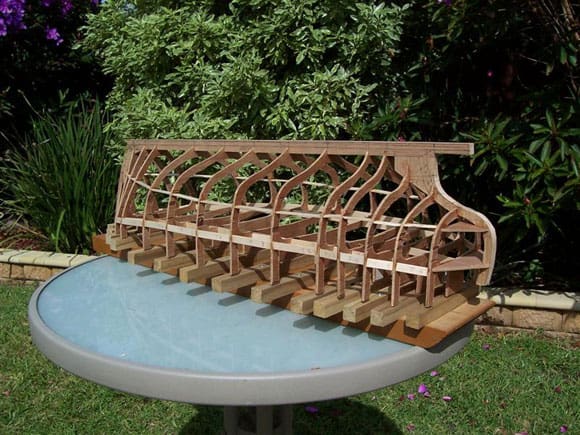
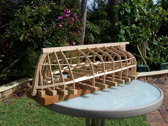
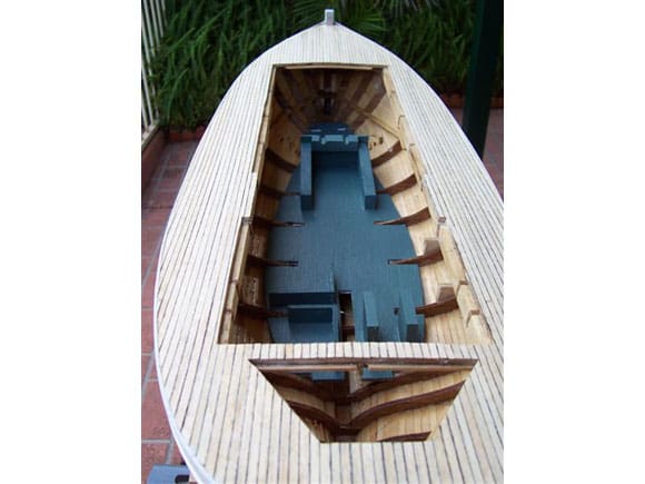
The overall dimensions of the hull are: length 760mm, breadth 250mm and keel to deck 180mm. A sturdy baseboard had some timber cross pieces fixed at right angles to the centreline to match the station spacing. The hull cross frames were clamped upside down to the baseboard, at their stations, using the frame extensions. The backbone of the keel, bow and stern pieces was fitted into the frames to form the basic structure of the boat. The main waterlines, numbers one and five, and the centreline were used to check that the deck and keel were in their correct alignment. The frames are maintained in their correct position by the insertion of permanent stringers on the line of waterlines one and five and at deck level. The stern area was filled with balsa and then shaped to provide a finished surface for attaching the planks. The inside was cut back to allow for operation of the rudder. Balsa blocks were inserted in the bow and keel to provide a landing for the planks. Photos 1 and 2 show progress thus far.
Planking
Double layer planking was adopted, using limewood strips (2mm by 5mm) for the first layer. After sanding the planks to a smooth surface, some automotive body filler was used to even out the hull shape. Planking was found to be difficult at the round stern with some planks ‘cut to fit’ for their best shape. The upper hull planks above the bilge line seem to lie correctly, but the lower planks to the keel were shaped to finish against the bilge line. The outer layer planking (0.5 mm by 5mm) was laid in a similar manner to achieve a more typical plank installation. It was mostly successful, but the stern area was difficult. All planks are glued to the frames and to each other. As I said earlier, it was intended that the finished surface, even though it would be painted, would have a planked appearance so as to represent the real wooden hull. Deck planking was laid over a false deck of sealed plywood, which had been installed after the frames were glued into place. The false deck was laid in sections to achieve the sweep and camber of the deck.
Deck openings were planned into the deck timber layout, so that after the deck had been glued to achieve camber and sweep, the openings could be cut through to allow the deck panels to be easily removed. Three openings were adopted, with one over the rudder, to allow for adjustment and removal, one under the wheel house and the last one under the hatch as close forwards as possible. These openings do not compromise the hull as the forward deck was left in place and a frame was left at the rudder. Removal of the wheel house opening allows for the other deck pieces to be removed by the judicious placing of a finger underneath the deck. These removable deck sections are supported on their edges by balsa blocks so that the deck remains flush. This lap joint provides a sealed joint to prevent water entry.
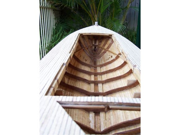
Bulwarks were constructed on a series of upright posts attached to the deck and then three layers of timber planks affixed. A suitable capping piece was installed and a mahogany veneer strip attached to the top surface. Waterproof PVA glue was used throughout the construction. Photo 3 shows the inside of the hull and the deck planking.
First flotation tests
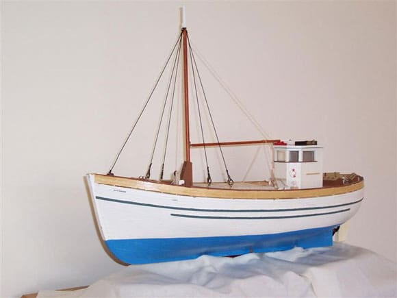
I thought it best to see if indeed the model did float, so there was a test session in the domestic ‘test tank’. On first launching, without any drive components, the hull was well balanced and floated with ease, which was a very satisfying result. I added trial ballast to check the trim and to establish how much weight in total would be required to have the model float at the correct waterline. Photo 4 is the unballasted model afloat. The hull was then painted with enamels to thoroughly seal and waterproof it, and the deck and interior of the hull were clear vanished.
Deck fittings
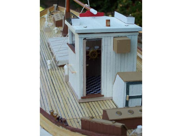
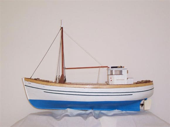
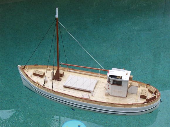
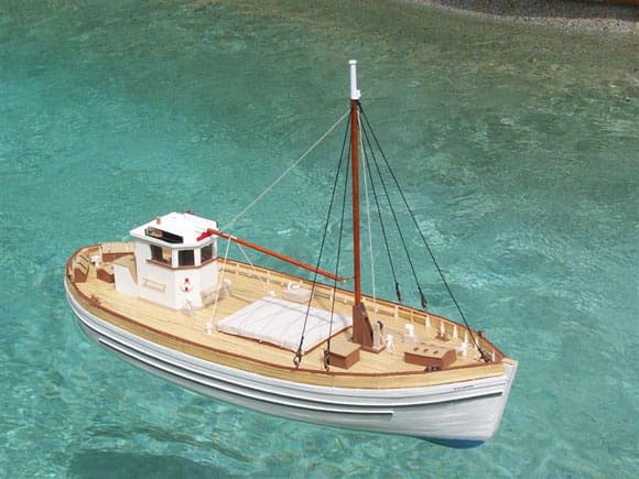
A number of work boxes are installed on the stern together with the deck skylight openings. The ventilators were made from small pieces of timber dowel cut at 45 degrees and rejoined at right angles for final shaping. The hold cover is made from calico to represent a canvas covering. The tabernacle is constructed from thin ply with the mast and boom from dowel. The mast stays (of elastic) are attached to the bulwark with latch clips for easy removal of the forward deck. The mast can be removed for storage and transport. The wheelhouse is constructed of ply and covered by veneer planks to replicate the original construction. The wheelhouse is a freestanding unit which is detachable from the deck if necessary. The internal wheelhouse furniture is simple and basic. Photo 5 is a stern view of the model.
Drive system layout
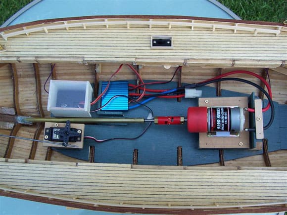
The line of the propeller shaft was drawn on to the elevation of the boat plan. Dimensions were estimated for the length of the shaft, shaft/motor coupling and the motor so as to confirm that the drive components would be able to fit within the hull and under the deck. The motor mounting was designed and a false deck constructed, upon which all the drive components would be installed. Photo 6 is of that false deck set into the hull. The main drive battery was located on a shelf just above the drive shaft and astern of the motor to ensure the centre of gravity of the boat was maintained.
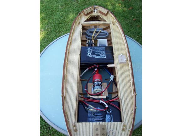
The rudder servo was installed on a small pedestal astern of the battery shelf, with the receiver placed in a covered enclosure for splash protection. The electronic speed controller was in front of the receiver under the battery shelf. Cabling was run loosely within the hull around the batteries as this allowed for ease of removal of all components. By unplugging the batteries from the electronic speed controller, a battery charger can be connected without the necessity to remove the batteries from the boat.
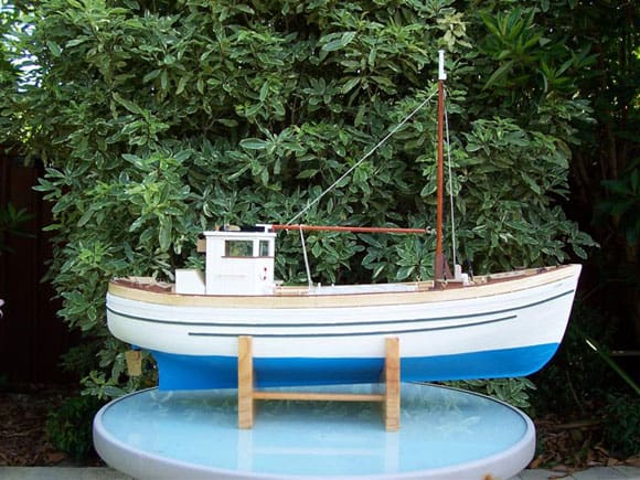
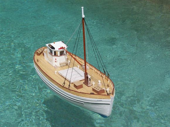
The on/off switch for the speed controller is installed under a services manifold which allows for diesel fuel, service water and potable water to be loaded onto the boat. The aerial is run on supports under the deck and within a plastic tube for protection and ease of removal. All drive components are removable including the false deck and battery shelves. Photos 7 and 8 are of the final internal layout. Photo 9 is a side view of the finished model and rather nicely shows the rising keel.
First sailing and sea trials
During the first sailing, the drive system was found to be very slow in operation, with only a minimum of speed control. Windy conditions would overpower the motor and steering was also difficult. Consideration was given to changing the motor to direct drive to achieve better speed control. However, on advice from the hobby shop, a second battery was installed to provide an increase in power. With the installation of the second battery, sailing performance was improved with full throttle control now possible. Scale speed is attained at half throttle setting, with some extra margin now available for better control. As an extra battery had to be installed, an additional shelf had to be inserted under the forward deck in front of the motor, which was a very tight fit. It was then found that some lead ballast was required in the stern to trim the boat back to the waterline. The motor used was a MFA Como drill motor with 10:1 gearbox driving a 35mm two blade propeller. I used a Futaba Attack r/c system with a ESC using a battery eliminator circuit. Power was provided (after the upgrading) by two 6v gel batteries.
Conclusion
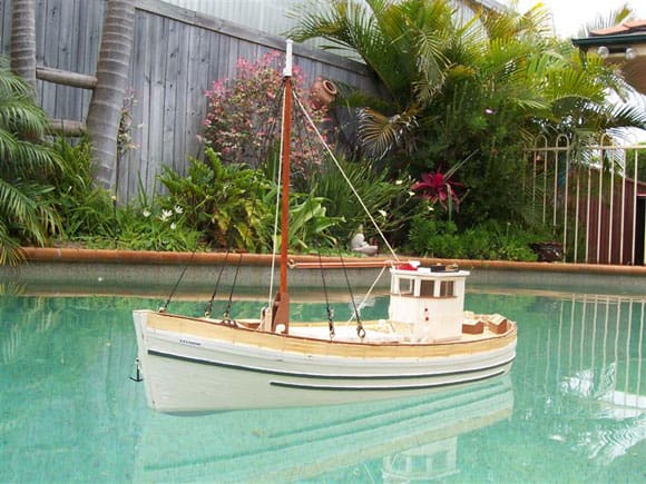
I called my model, ‘Motorised Model Boat (MMB) Graesan’ and she was launched and sailed on the 1st January 2007 – middle of summer for us in Australia! Construction of the model was entertaining and challenging (for a first time modeller), with much thinking and trial assembly required to complete the model, particularly with converting the information on the plan to cut and prepared wood. The appearance of a planked model boat, with the planking showing through the paint has been achieved and is I consider to be most realistic.
Manoeuvrability has, subsequent to initial sailings, been improved with the fitting of a larger rudder. I think that a three bladed propeller will be the next modification to try and improve overall boat speed.
References
1. Model Boats free plan, October 2004, 45ft Admiralty Trawler by James Pottinger.
2. Radio Control in Model Boats by J. Cundell.
3. The Complete Marine Radio Control Manual by H. Bright.
4. Scale Model Ship Propulsion by T. Gorman.
5. Model Boats magazine general advice and articles.


