The world's leading magazine for all model boating interests
Shemarah II
Shemarah II
Home › Forums › Scratch build › Shemarah II
- This topic is empty.
-
AuthorPosts
-
22 May 2012 at 08:57 #34541
Gareth Jones
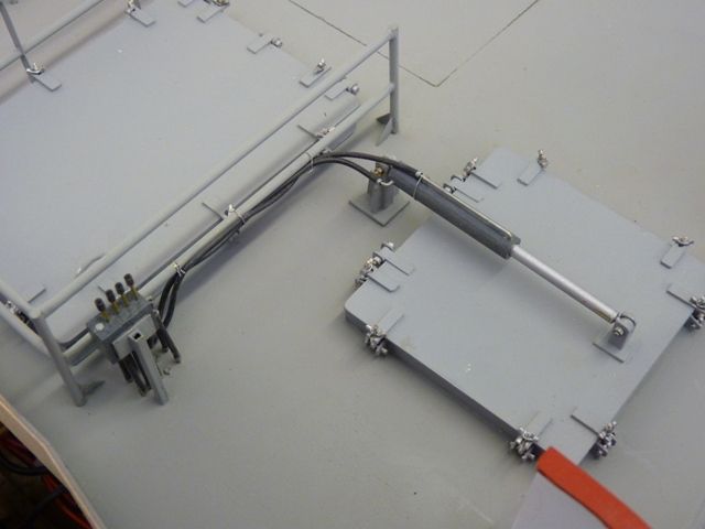
Participant@garethjones79649The last few weeks I have been occupied with developments around our new pond and a loveable but frustrating trainee hearing dog called Bobby. However I have managed to make a bit more progress on Shemarah in the last few days. I have completed the cod end hatch hydraulics using brass wire and small bore silcon tubing to simulate the pipes and hoses. A few bits of spare plastic and brass made up the control valve assembly which I guess also controls the main crane, or perhaps I should call it a derrick. (Why do they call cranes on ships Derrick? Its almost as puzzling as why firemen call their engines Dennis). I have also fixed the hatch to the deck and painted the hand rails around the main off loading hatch.
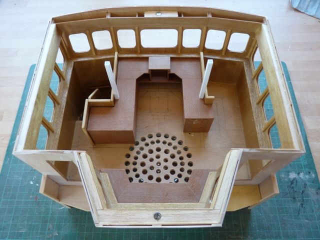
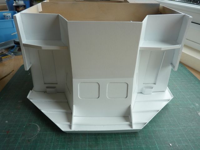
I finally plucked up courage to start the wheel house roof which has lots of complicated curves and angles. I plan to add a lot more detail inside the wheelhouse but at a much later stage in the build. Therefore the roof needs to be fixed in place but easily removable at some stage in the future. There are lots of lights attached to the roof and mast and these will all need wiring in, together with the radar drive motor. The plan is to fit a ceiling over the wheel house and run the wiring up through two vertical conduits, which are part of the real vessel. The roof will fit over this ceiling with the electrical connection made using a pair of servo lead connectors laid flat between the two parts. All will hopefully come clearer in the pictures.
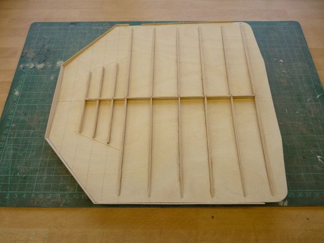
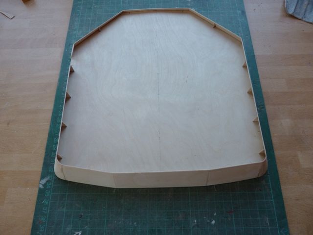
The roof was cut from 1/32" ply sheet using the outline shown on the plans, which was quite straightforward. The camber on the roof was formed by adding a number of stiffeners on the underside as shown below.
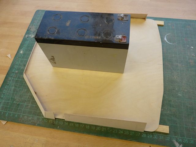
The edge pieces were added using small gusset plates to hold them at the correct angle which is canted in by 30 degrees from the vertical. These side pieces vary in height but the bottom edge of the whole perifery is flat on the same level and overhangs the roof by about 3 mm vertically. This was achieved by packing the roof up from the building board by 3 mm and weighting it down with a battery. Strips of 3 mm timber were placed under the edges to make sure the ply sheet did not twist or warp as the edges were glued on piece by piece.
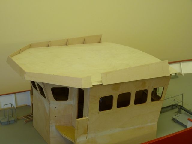
The cut out in the bottom left corner is where the ladder to the roof is attached. Heres the roof resting on the wheelhouse with the just the front edge to add. The middle bit will be straightforward, the tricky part will be the two front corners where the edging is curved rather than flat. Hopefully this will be achieved using a paper template and boiling the ply sheet in the kettle for a few minutes to make it pliable enough to form the curve.
Edited By Gareth Jones on 22/05/2012 08:59:11
22 May 2012 at 09:10 #34543Bob Abell 2
Participant@bobabell2Hi Gareth
I like the quality of your work and the patient slow but thorough build!
Keep up the good work
Bob
22 May 2012 at 09:25 #34547Gareth Jones
Participant@garethjones79649Glad you like it Bob. Shemarah will be on the Goole MBC stand again this year at the CADMA show in 3 weeks time. Just like last year, people can come along and fondle its bulbous bow and bottom to their hearts content.
Gareth
23 May 2012 at 08:14 #34554Gareth Jones
Participant@garethjones79649The wheelhouse roof edging has been completed now with just a smidge of filler needed where the two front corner curved sections are butted up against the straight ones.
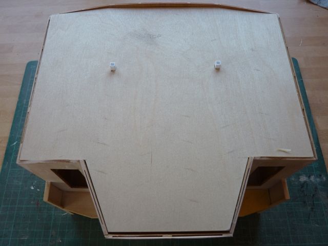
Heres a picture I referred to yesterday showing the conduit/trunking up through the wheelhouse where the wiring will run to the roof. On the centreline at the front and back are two 6 mm diam magnets which will secure the roof on to the wheelhouse trapping the ceiling between them. I will probably fit captive nuts in each corner eventually, with small countersunk screws through the roof corners.
Here is the ceiling fitted, not yet painted or sanded just laid in position. It might need some stiffners added and the underside will have to represent the real wheelhouse ceiling and lights.
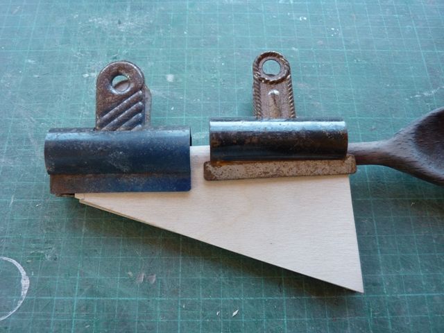
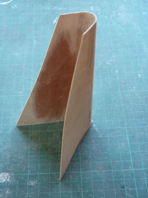
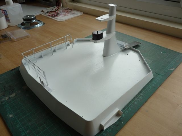
The next photo shows the start of the steel mast fitted on the wheel house roof. As usual the 1/32 ply has been submerged in boiling water for about 10 minutes before wrapping round a wooden rod, in this case a spoon which came to hand in the kitchen.
After drying in the sun yesterday afternoon the ply was ready to start adding all the internal diaphragms to hold its shape properly and then there are numerous antennas to be added, including the radar and its drive motor and a number of lights. At the moment I am not sure whether I will fix the mast permanently on top of the roof or make it detachable for storage and transport purposes. It looks like the mast will be the main project for the next few weeks, then there are the railings and lights to be added to the roof and the steps, handrails and ladders to be added on the wheelhouse.
24 May 2012 at 21:28 #34587Gareth Jones
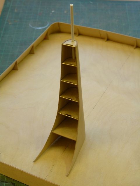
Participant@garethjones79649Todays little step with Shemarah was to build the mast structure. Apart from the bottom one, each of the internal diaphragms has a hand hold cut out, made using a short length of brass wire across the aft edge. Sticking the diaphragms inside the main skin was a real struggle as it was difficult to see if they were level and in the right place, and because of the tapered shape they kept being squeezed backwards.
There is a flood light mounted on top of the mast and the wiring for that and the radar and stern light will pass through holes drilled in the front edge of each diaphragm before assemby. I remembered to drill all 6 holes……..except the third one down from the top.
15 June 2012 at 09:57 #34895Gareth Jones
Participant@garethjones79649Sometimes you seem to take two steps forward and then one back. After giving the mast a coat of primer it was apparent that it was twisted and not symmetrical. I therefore had to remove most of the horizontal diaphragms and make new ones. I also realised that the real vessel has two hand holds in the aft edge of each diaphragm not one so I made the new ones to the correct pattern.
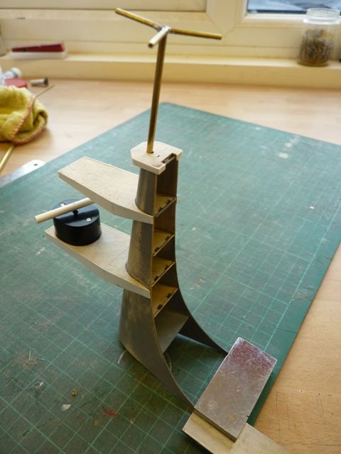
I have also added the platforms that support the antennas and, using brass tube, the extension on the top of the mast which supports a small forest of vertical aerials.
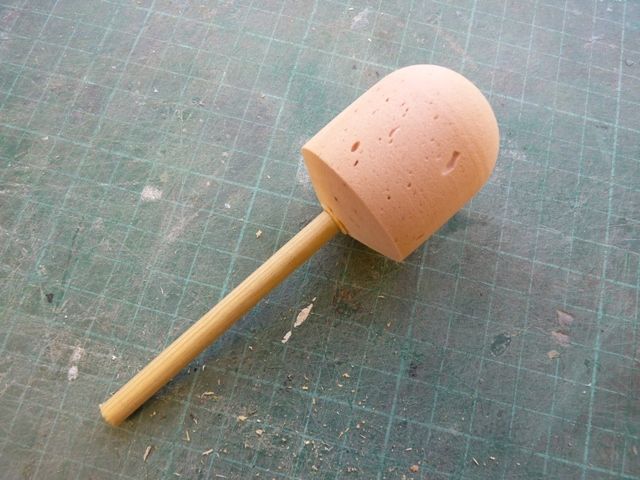
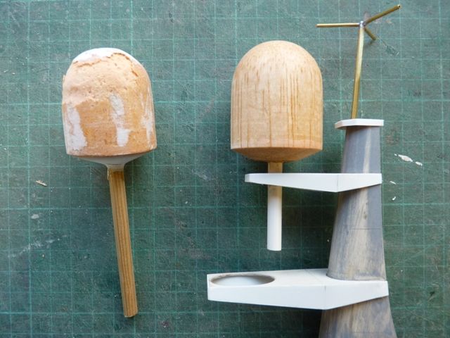
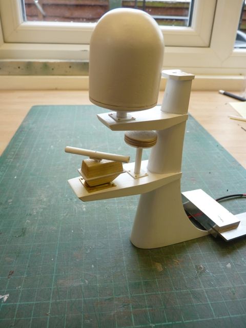
There is a visible rotating antenna on the lower of the platforms so I have used a Robbe geared motor to drive this. The motor in its casing is not to the scale size and shape but with a few additional bits added to the casing to make it look more realistic it should be fine. On the upper platform is a large cylindrical housing with a hemispherical top. I dont know what this is, possibly some sort of sat nav system antenna. It was not fitted at the time the plans for Shemarah were produced but its a prominent feature of the boat now so I have scaled it from the photos I have, and its around 40 inches in diameter and 45 inches high.
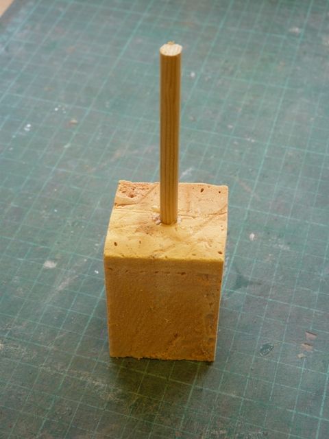
My first attempt at this was using some foam insulation I had in the shed, drilled to take a piece of 6 mm dowel.
This was sanded in my pillar drill and then coated in resin to fill the voids and produce a hard shell. After adding a bit of filler in some places I then tried to get the final surface finish using the pillar drill again but great chunks of the foam peeled off. I then had another go, this time laminating 4 sheets of 3/8 inch balsa and this was much more successful.
The supporting plastic rod needs to be cropped to size but I will leave it long for now to make painting easier.
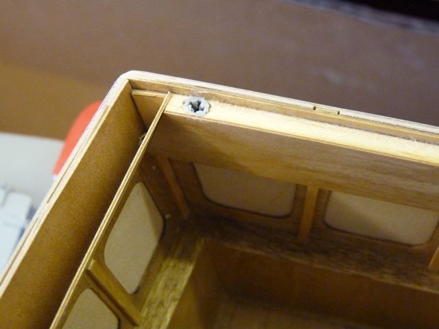
Initially I attached the roof of the wheelhose using two 6 mm high power magnets but sailing on the pond at Goole a couple of weeks ago it was apparent that this wasnt enough as the roof blew off in a relatively light breeze. There is no really substantial structure underneath to screw into so I decided on a number of small wall plugs set into the balsa fillers around the side.
Small countersunk brass screws through the roof will be camouflaged with paint and hold the panel down much more securely and with a better fit against the curvature of the wheelhouse sides.
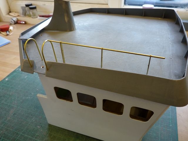
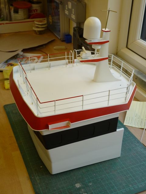
I have now started the hand rails along the top of the wheelhouse using 1/16 brass wire for the top rail and 3/64 for the two lower rails. The stanchions are flat brass strip rather than circular section. I next need to take the rails around the corners and there is a gap at the front were the derrick rests but I have a plan for this which will be revealed in the next post.
18 June 2012 at 09:40 #34939Gareth Jones
Participant@garethjones79649The handrails are now complete.
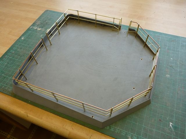
I marked the position of the rails and stanchions on the top of the wheel house and then bent the top wire to the correct shape. This was then used as a pattern to make the two lower wires. When I was satisfied everything would fit I drilled the holes for the stanchions in the wheelhouse top and threaded the stanchions on to the three wires. With all the stanchions in place and located in the holes in the wheelhouse they were all soldered . I chose to solder them in situ as the wheelhouse top is cambered and the stanchions are not all at right angles to the rails.
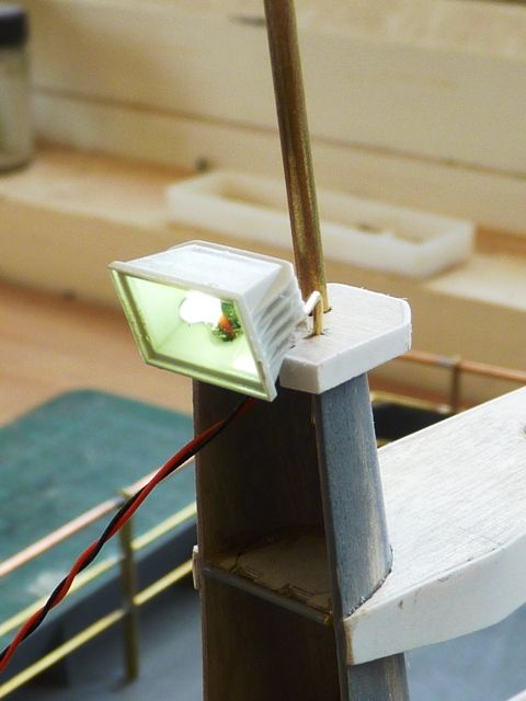
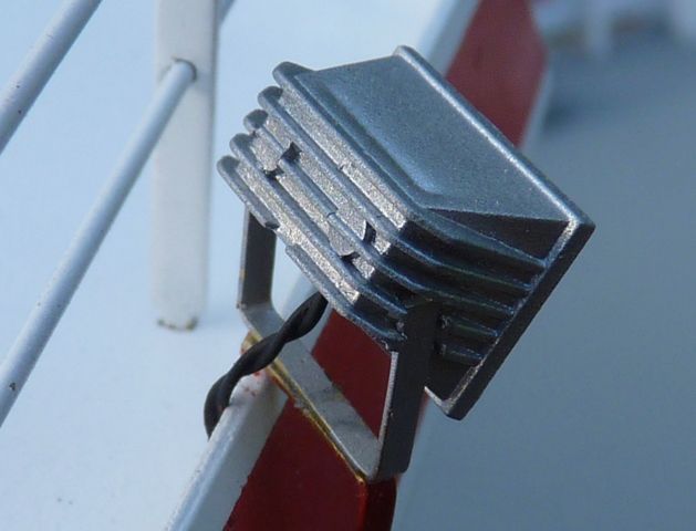
The next step has been to make a start on the lights which are attached to the wheel house roof and mast. I have decided to use LEDs for all the lights rather than filament bulbs as on my previous models. There are a number of halogen floodlights on the wheelhouse and I like the Robbe version of this but have always found the mounting to be rather fragile. I have been experimenting with some alternative options using brass wire to mount them rather than the little bit of plastic supplied.
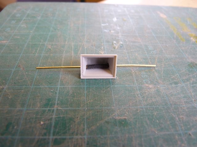
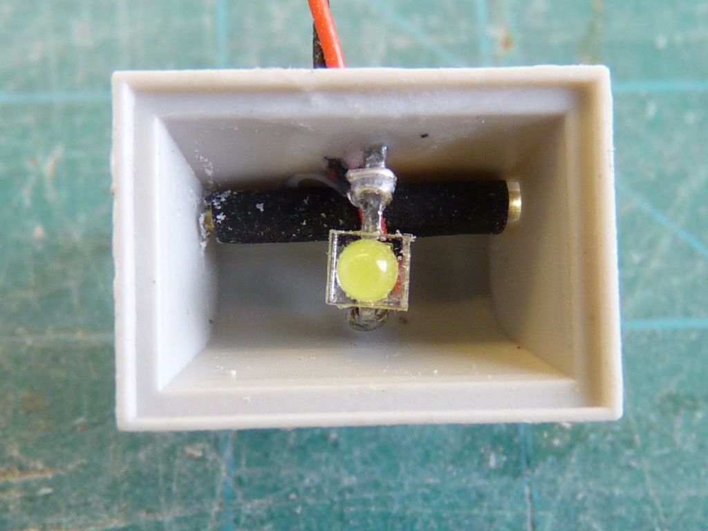
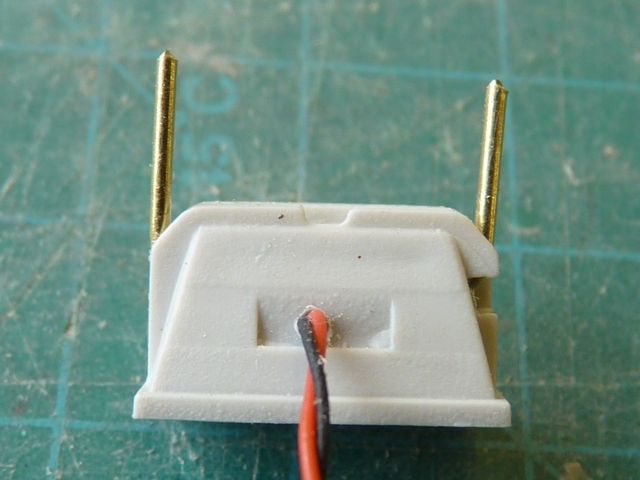
I drilled through the back of the lamp housing and threaded a piece of 1/32 brass wire through with a short length of heat shrink in the middle to reduce the risk of shorting out the back of the LED.The LED wiring was threaded through the bottom of the lamp and in the picture above, the brass wire used to mount the lamp has bent bent back as shown in the picture below. The LED is a 2.1 mm unit from Component-Shop. Depending on the location, the LEDs will all be connected to a 12 volt supply, in some cases singly and in others with two or three LEDs in series. Appropriate value resistors will be used in each case.
This seems to work quite well and has the potential to be a much more robust mount for the lamp. I think that the 1/32 mounting wire looks a bit too thick and I will probably reduce the size in the final version to 0.5 mm.
The light seems bright enough and I will be using the same sized LEDs in all the flood lights, nav lights and trawling lights. I have also bought some smaller units for use in the wheelhouse instrument panels and displays.
Edited By Gareth Jones on 18/06/2012 09:42:34
21 June 2012 at 13:56 #34978Gareth Jones
Participant@garethjones79649Work has progressed a little more on the wheelhouse roof. I have added the roof beams under the extended rear section and the cover plates over the two doors. I am not sure what these actually cover, maybe its a ventilator panel or something underneath.
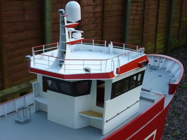
On the top of the roof I have added the navigation light boards and the support for the derrick boom which rests on the front of the wheelhouse roof when it is not in use. The roof has been painted white and the railings are in the process of being painted as well.
I am starting to have second thoughts about the radar drive motor as it now looks a bit too big and out of place on the mast. I was going to camouflage it a bit and paint it white but it will still not look like the real thing. The option I am considering is using an alternative motor mounted inside the mast itself, rather than on the shelf which projects forward. A pair of small pulleys and a belt drive under the shelf could link the motor drive shaft and the radar and be pretty well hidden. However it would be more involved mechanically and require the construction of another mast. While I ponder the way forward I am going to continue work on the roof with the nav lights to fit and the rest of the painting to complete.
Edited By Gareth Jones on 21/06/2012 13:57:35
24 June 2012 at 17:32 #35028Gareth Jones
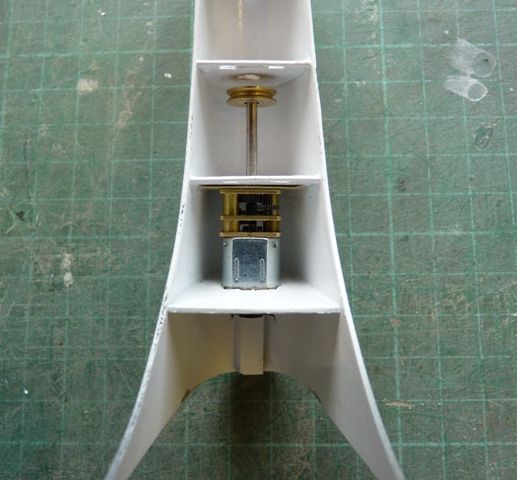
Participant@garethjones79649This afternoon I have been tinkering with the radar drive and I am now on the Mk 3 mast. Fortunately I have not had to start from scratch as I have been able to modify the old one without too much trouble.
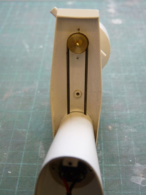
The motor is a Modelling Timbers 6 volt long shaft motor which has been robbed from my wife's Mouseboat, where it drives the hamster wheel. The body of the motor passes through the bottom diaphragm of the mast and will be retained by a collar, glued to the end of the motor body and screwed to the diaphragm from below. There is a small spigot on the top of the gearbox and that engages in a thin brass plate, glued to the next diaphragm up. The drive pully will be superglued to the shaft. There is rather a long overhang on the shaft which is going to put some extra load on the bottom bearing but as long as the driving band is not too tight it should be OK. Its not as if the motor is going to run for hundreds of hours.
I will have to make a new shelf for the radar antenna and simulated drive motor to sit on and the pully and drive belt will be hidden by the flange of the shelf. Well that's the plan at the moment, the next job is to make the new shelf and radar head, while I await a replacement motor to fit in the Mouseboat.
30 June 2012 at 08:59 #35106Gareth Jones
Participant@garethjones79649I have now made the new radar shelf and scanner drive head. Finding a suitable rubber band to connect the two pulleys was more problematic than I expected. Even though I have a plastic bag full of assorted sizes none was a suitable length or thickness. I did a bit of research on the net and there are suppliers of small drive bands for electronic equipment such as DVD player trays and tape decks. However most of them did not specify the size of band, just the equipment it should be fitted in. On a few sites I did find the suggestion that if you cannot find the right size rubber band, repair the old one with superglue.
This idea is not as far fetched as it might seem as I can remember, many years ago in the early days of superglue we had a demonstration at work by Loctite, where an engineer cut a rubber o ring with a razor blade, glued it back together with the new magic superglue and then hung what seemed a huge weight on it to prove it was as good as new.
I have a number of surplus pieces of 1 mm thick neoprene rubber pond liner stored away in case they come in useful and I decided to make my own drive band. I carefully cut a straight edge about 12 inches long on one side of the sheet and then sliced off a length approximately 1 mm wide. It was difficult to cut the piece of even width as the rubber tends to move under the straight edge as its being cut, even using a new clean sharp knife blade. I measured the length around the pulleys using a bit of fishing line and then took off 10% to allow for some tension in the band, ending up with a figure of 112 mm. I then cut the slice of neoprene to length and glued the ends together using a tiny drop of superglue. It took a few goes to get the ends lined up and held steady for a few seconds while the glue sets but with a bit of practice its not difficult. If it doesn't look good enough, just cut the rubber again near the joint and re-do it. The finished bands seems to work fine. I think 10% extension was a bit too tight so I made the final unit and a few spares with somewhere around 5-7% extension.
I have run a short endurance test and the rubber band lasted 30 minutes with no sign of deterioration. I have enough neoprene to make millions of spares so the idea looks like a success at the moment. Time will tell if it works in the long term.
Here is the rubber band in position round the scanner drive head pulley.
Heres the mast with the radar antennas fitted and ready for painting.
I have now painted the black band around the windows in the wheelhouse and the red edging to the roof. I have also started painting the top rail of the railings, prior to finally fitting them to the roof. The next step is painting the nav light housings matt black and then fitting the nav lights and all the other lights on the roof and mast.
30 June 2012 at 09:26 #35107Bob Abell 2
Participant@bobabell2Excellent work, Gareth
Bob
6 July 2012 at 20:54 #35185Gareth Jones
Participant@garethjones79649The wheelhouse has progressed a bit further this week and since most of this weekend's local regattas have been cancelled due to flooding or weed problems I might get a bit more done in the next couple of days.
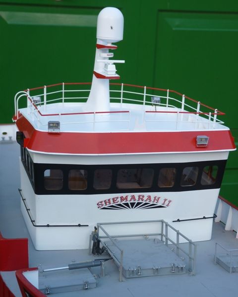
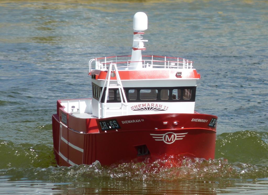
I have added Shemarah's name and the sunburst logo on the front of the wheelhouse and sprayed the matt black area around all the windows. I then sprayed the whole wheelhouse with a couple of coats of satin varnish and fitted all the windows. It was a bit of a pain cutting all the wheelhouse panels three times about 6 months ago but it was well worth it and all the windows were cut and slid into place in a couple of hours with no glue or paint to worry about on the clear plastic.
I have also added the handrails that run around the sides and front of the wheelhouse.
I have also fitted all the nav lights and flood lights to the roof and mast. In the end I modified my mount for the flood lights to make it more representative of the real installation. Instead of the planned wire through the back of the light I used a piece of thin flat brass strip, bent and then glued on to the sides of the lamp housing. The cooling fins on the lamp housing were cut away as required to allow the mounting brackets to fit neatly on the housing with the lamp at the correct angle for its location.
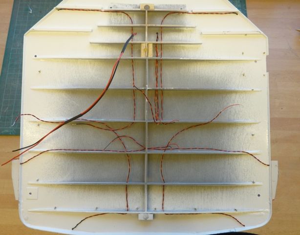
The next step is to connect up all the wiring under the roof to a pair of flat servo connectors which will provide a wiring break to allow the roof to be removed.
All the wiring has been routed through holes drilled in the ribs under the roof so that it is neat and tidy. After fitting the connectors I think I will have a bit of a change of scene and start work on something other than the wheelhouse, probably either the A frame over the cod end hatch or the mast and derrick near the bow.
Edited By Gareth Jones on 06/07/2012 20:56:25
15 July 2012 at 17:20 #35287Gareth Jones
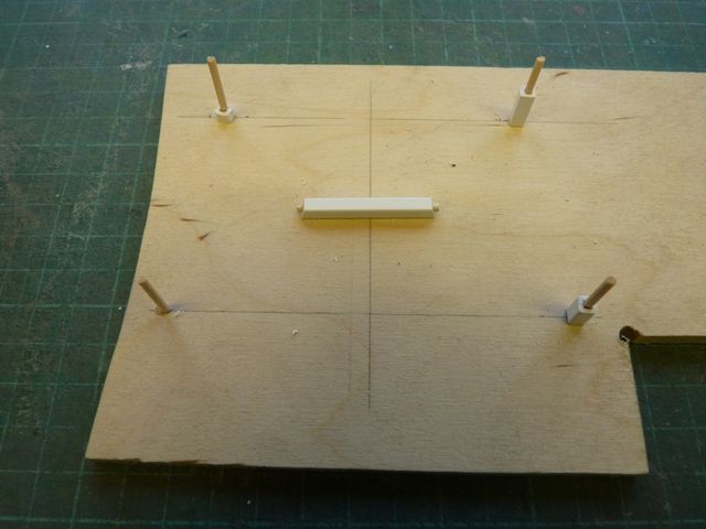
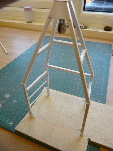
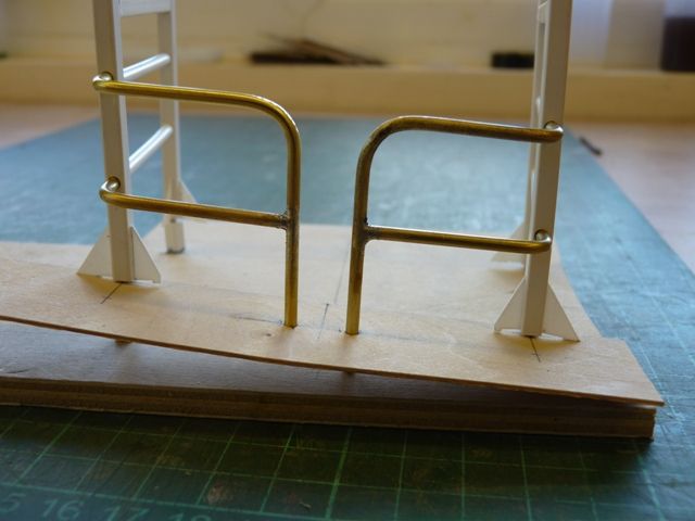
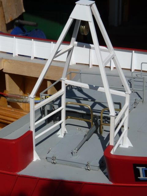
Participant@garethjones79649This week's project has been the A frame over the cod end hatch. I have built this mainly from 4 mm square polystyrene tubing, although the guard rails at the inboard side were made from 3/32" brass rod. The four bottom uprights are all different lengths because of the sheer and camber on the deck. To make it easier to assemble the parts I made a little jig using pieces of cocktail sticks to locate the upright tubing with three spacers to effectively create the deck datum.
The joints between the tubes were reinforced with pieces of cocktail stick and there is a typical cross piece lying in the middle of the jig. Assembly was a bit fiddly and my disc sander earned its keep trimming all the ends of the tubing to the correct angles. Its really useful for this sort of job as its possible to make small repeatable adjustments to an accuracy of around 1 degree.I had to modify the jig slighly to provide a couple of extra locating holes for the inboard guard rails and hold them in the correct position while they were soldered.
With hindsight it was a mistake to have glued the cod end hatch on the deck about 3 months ago. It would have made fitting the A frame much easier and also made it easier to attach the corner gusset plates in situ. The position of the A frame is effectively dictated by the cut out in the bulwarks and the hatch is then located centrally under the A frame. Fortunately everything fitted reasonably well but if you ever build one of these, fit the hatch at the end, not the beginning.
Shemarah has also been back in the pond to allow me to label the ballast weights correctly.
The next job is to remove the rear electrical tray for a small wiring mod to provide a 6 volt supply to the radar motor rather than 12 volts. After that I think I will make a start on the main mast and derrick.
16 July 2012 at 08:26 #35290Dave Milbourn
Participant@davemilbourn48782Gareth
To save you fitting a 6v battery have you thought about running the radar from the 12v supply via a 6v regulator? If this is the only 6v device then the current will be very low, and a regulator is much easier to fit than a 6v battery (and you don't have to charge it up either).
(Just read your post again and realised that you might mean doing just that; in that case this info could be useful to others if not you!)
Dave MEdited By Dave Milbourn on 16/07/2012 08:29:10
16 July 2012 at 08:46 #35291Gareth Jones
Participant@garethjones79649Dave,
You are correct in your assumption at the end of your post. I took your advice a while ago and fitted an MFA adjustable voltage regulator which presently supplies the water pump and is controlled by one of your 4 channel switch units. I need to modify the wiring so that the regulator also supplies the radar motor with about 6 volts and is also controlled by the switch unit.
I will update my wiring diagram for future reference at the same time. Would you be interested in a copy when its been tidied up?
Gareth
16 July 2012 at 23:51 #35299Dave Milbourn
Participant@davemilbourn48782I certainly would, sir!
DM22 July 2012 at 18:43 #35386Gareth Jones
Participant@garethjones79649No detail photos of Shemarah this week as most of the work has been on the wiring. I have modified the internal wiring to provide a switched 6 volt supply to the radar scanner motor and begun to fit the wiring between the wheelhouse connector and the equipment in the roof. I have included a connector break so that the roof can be removed to leave the inside of the wheelhouse accessible for future detailing. However initial experience suggests that removal of the roof will not be quick and simple but more of a dockyard job, so if you want to look inside the wheelhouse it will have to be through the windows or open doors.
Shemarah went for an outing to Goole to test the system and it all works fine except the overboard water pump needs a bit of adjustment to reduce the supply voltage and balance the outlet flows. Reducing the voltage will not be an issue for the radar motor so that is quite straightforward, My main concern is the radar motor installation is very noisy so I might at some point move to a Mk 4 mast with the motor mounted inside the wheelhouse under the roof.
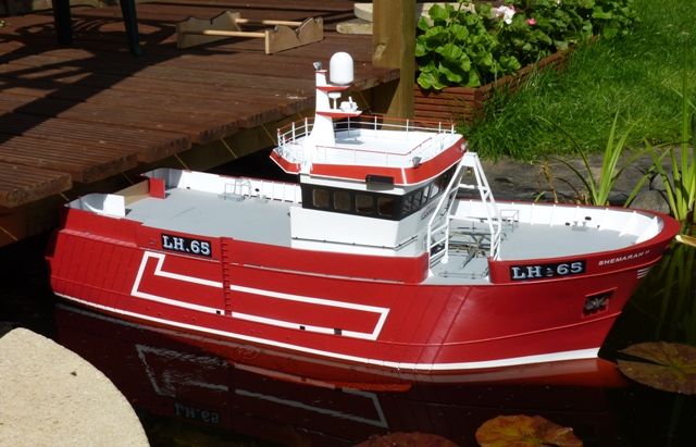
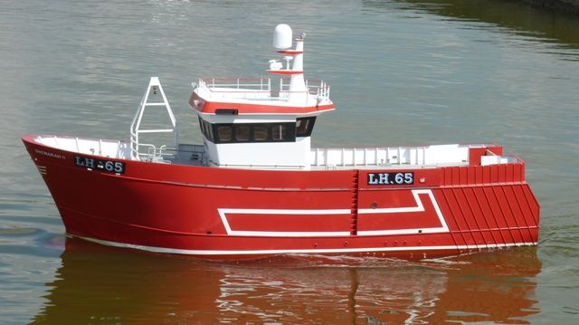
On the pond Shemarah looked good in the sunshine, which was a rare treat this weekend.
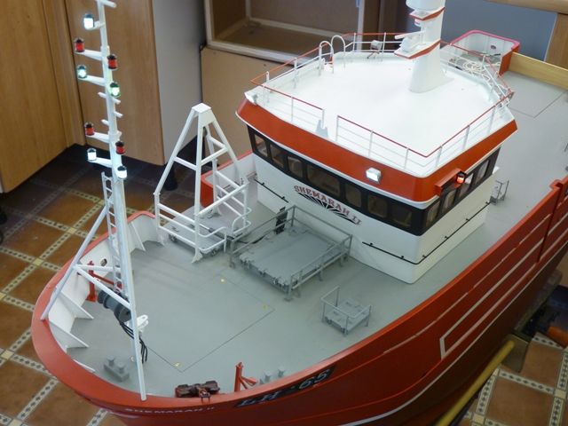
The next area of work will be the forward mast and derrick and the anchor windlass and winch. Donald Moodie, the skipper of the full sized Shemarah has kindly sent me some photos of the windlass so I have no excuse for not detailing it accurately.
31 July 2012 at 20:15 #35544Gareth Jones
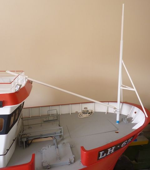
Participant@garethjones79649The mast and derrick have begun to take shape over the past week. The mast is made from three concentric styrene tubes, 1 mm thick, the bottom one being 8 mm OD, the next 6 mm OD and the final one 4 mm OD. The mast is to be removable and will locate in a 10 mm aluminium tube which will be set into the hull.
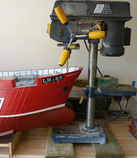
I had already drilled a pilot hole for the mast but left the final drilling until now. The hole has to be drilled through several interlocking ply sheets and it is difficult to be sure it will be truly vertical using my trusty cordless drill. I therefore manoevered Shemarah under the pillar drill and drilled the 10 mm hole using that instead.
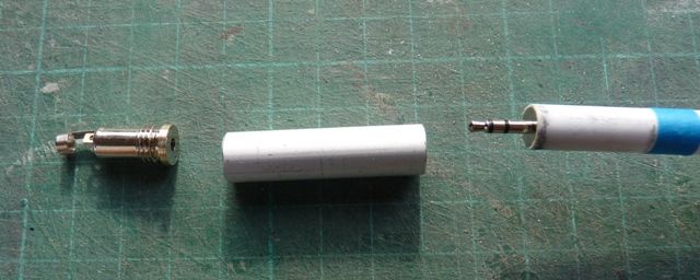
There are two lighting circuits in the mast so I am using a 2.5 mm stereo plug and socket to make the connections. The socket will be fixed in the aluminium tube in the hull and the plug inside the bottom of the mast so that all the wiring can run up inside the mast.
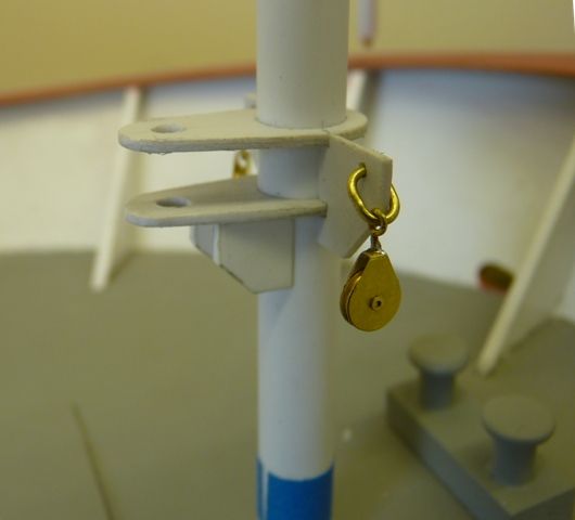
Here's a view of the basic mast and derrick. The gooseneck connection at the end of the derrick is made using one of Modelling Timbers very versatile tie downs as the vertical and horizontal pivot point. I have also used their pulley blocks for the lifting and guying wires but I modified them to have a larger hanger 'eye' using 1/64 dia, wire in place of the bits supplied.
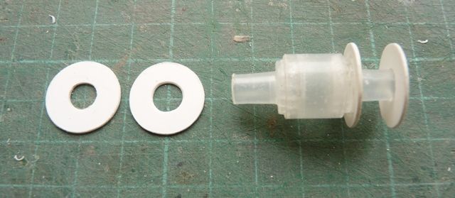
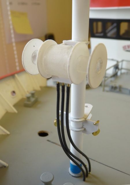
The guying winch has been made from 2 cannibalised hand wash liquid dispensers, which contain a useful little pump with assorted tubes and springs which I occasionally collect. The drum ends have been cut from styrene sheet. Heres the winch under assembly. I dont know what plastic the hand wash thing was made from but it was a b*****r to glue together. I eventually found a superglue that worked reasonably well but everything else just would not stick.
And here is the installed unit, just tacked on to the mast for now. One problem I have with styrene is that I find it difficult to achieve a nice clean crisp edge, mine usually end up being a bit whiskery where they have been trimmed or sanded.
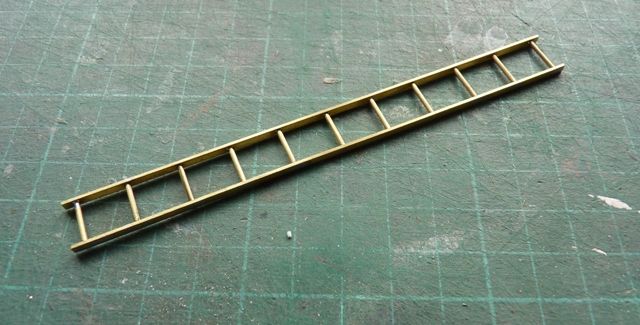
I have made the upper ladder which fixes to the front of the mast, using brass strip for the sides and rod for the rungs, all soft soldered together. Fixing the ladder on to the front of the mast will be the next challenge. There are six thin strips of brass needed which can easily be soldered on the ladder sides but getting them the right angle and length to locate in the mast will not be easy.
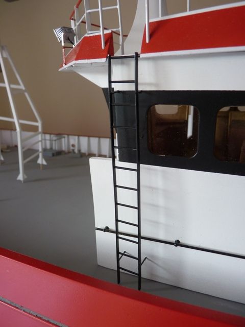
While I was in ladder mode I also made the ladder which fits on the right hand side of the wheelhouse. In this case fixing it to the wheelhouse side was much easier.
18 August 2012 at 18:06 #35923Gareth Jones
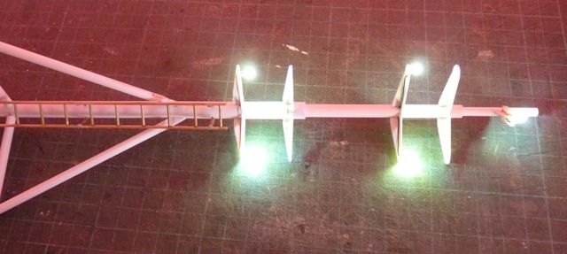
Participant@garethjones79649Wiring the lights in the mast has been the latest challenge on Shemarah with some success and one notable failure. There are 5 LED's connected using single core wire from Component Shop. The wire is very small diameter around 0.5 mm and proved reasonably easy to solder to each LED and then feed in through a hole in the side of the mast and down to the bottom, making 10 wires in all. I left around an inch protruding from the bottom of the mast and soldered the required resistors in series or the conductors together where the LED's are paired.
All the LED circuits are supplied from the main 12 volt battery so an individual white LED requires a 435 ohm resistor in series with it and 2 white LEDs in series need a 270 ohm resistor. The joints were insulated with heat shrink and then the connections made to the 2.5 mm coaxial connector using a multi core wire for robustness. The bundle of wires was then taped together to take any physical loads off the soldered connections. I tested the whole assembly and everything worked fine as shown in the photo below.
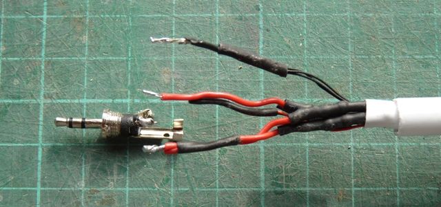
I now had the job or persuading about 6 cm of wire, heat shrink and resistors to feed up into the bottom of the mast so the connector would fit flush with the end as planned and shown a few photos above. The picture below shows the problem, albeit taken at a later stage with the connector desoldered.
At this point I had one of Bob Abel's eureka moments. If you hold the mast and gently twist the connector the wiring inside the mast coils up and pulls the whole lot gently upwards. Brilliant I thought and superglued the connector into the bottom of the mast. Unfortunately when I came to check the assembly again, this time using the mating connector wiring, only the mast head light worked, the other 4 LEDs stayed resolutely unlit. After some coaxing I managed to get the connector free from the end of the mast and found the problem was in the connector itself, but it means I need to fit a new connector as I damaged it during removal. However at least its easier than trying to repair a broken connection somewhere inside the mast. In principle the process works and with a bit more care in soldering the connections so that I dont overheat the coax connector next time everything should be OK.
22 August 2012 at 12:19 #36050Gareth Jones
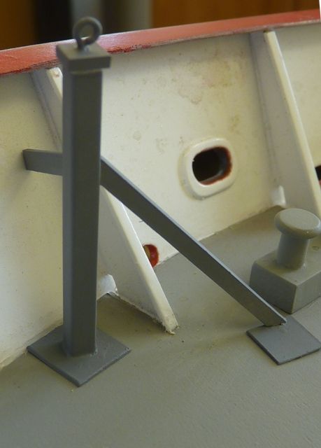
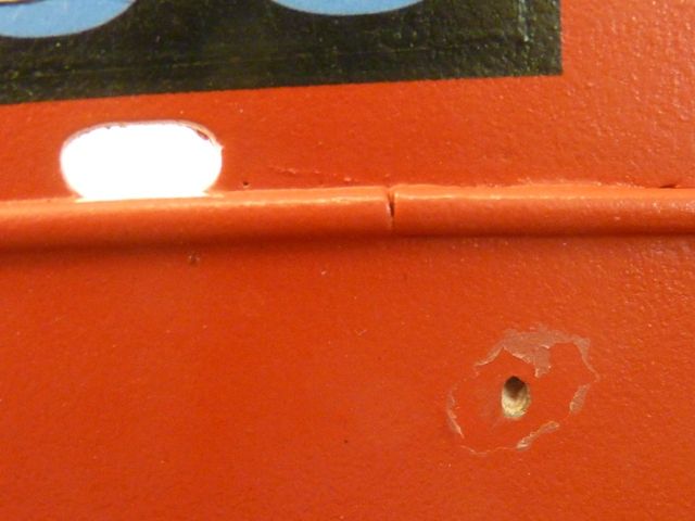
Participant@garethjones79649I had the opposite of a Eureka moment yesterday, more of an 'oh bugger' moment really. I was making and installing the guy posts for the derrick on Shemarah. These followed my tried and tested method using square plastic tube with the joint to the deck reinforced by an internal cocktail stick. While drilling the deck on one side I got slightly carried away and managed to drill through the side of the hull as well.
I know the attachment of the bracing strut to the reinforcing plate on the deck looks odd, and is nothing like the arrangement shown on the plan, but that's the way the real ship is constructed and I have the photos to prove it.
31 August 2012 at 20:26 #36219Gareth Jones
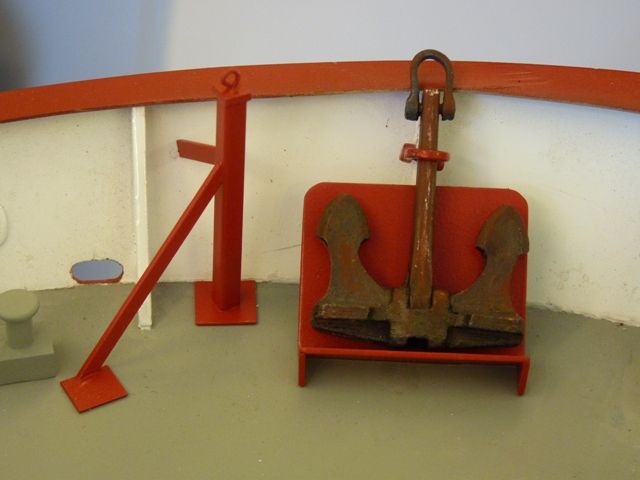
Participant@garethjones79649The guy posts have been painted and fixed to the deck and the accidentally drilled hole in the hull side has also been filled and painted. Hiding the hole was not a problem but the area around it where the polyurethane varish has peeled off will be more problematic. I guess I will have to respray the area again with varnish. I have also made the stowage for the spare anchor which Shemarah seems to carry. Although its not shown on the plans it does appear in the photographs I have aquired over the last two years.
I have also finished the wiring to the mast and the lights on the wheelhouse roof. I have found the LEDs in the lights on the mast to be too bright, even though the LED lens is pointing vertically upwards into the top of the lamp, rather than outwards. As a result I added an additional resistor in series with these lights to reduce the brightness.
I have now started work on the anchor windlass/winch and the liferaft container which also sits on the foredeck.1 September 2012 at 06:56 #36224 Paul TParticipant@pault84577
Hi Gareth
On the subject of over enthusiastic drilling I have just done exactly the same thing on my current Huntsman project and I have to admit that oh bugger wasn't the first thing that sprang to mind.
I do like the stereo jack method of getting power to the mast lights, its a system that had never occurred to me and is something that I will definitely use on my detachable masts in the future although given my ham fisted approach to launching and handling, where I tend to bend or break things, I think that I will opt for the larger. longer and stronger jacks similar to those used on electric guitars.
Paul
6 September 2012 at 15:25 #36335Gareth Jones
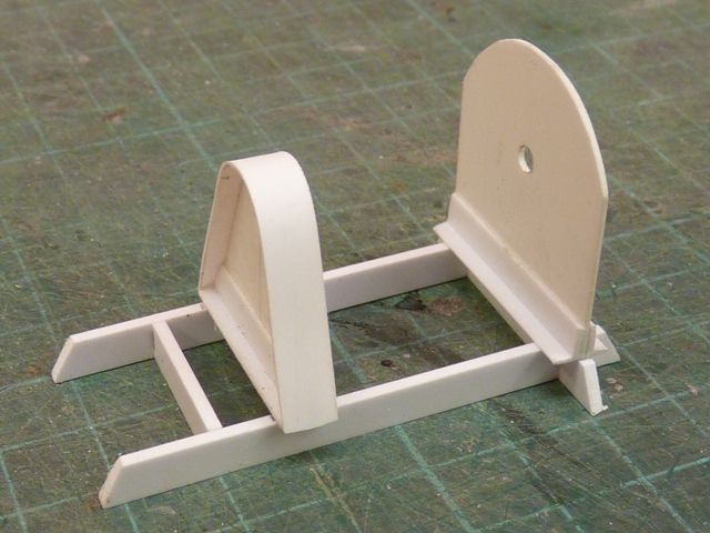
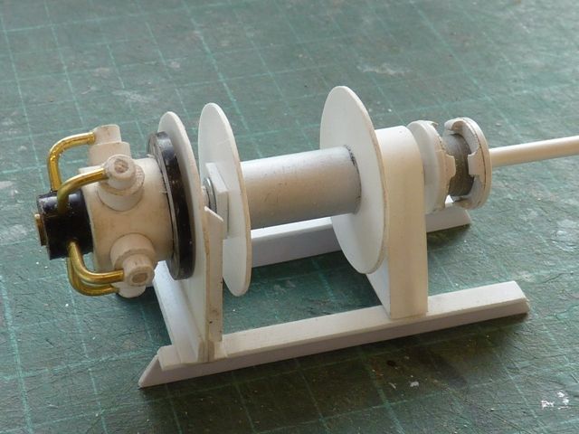
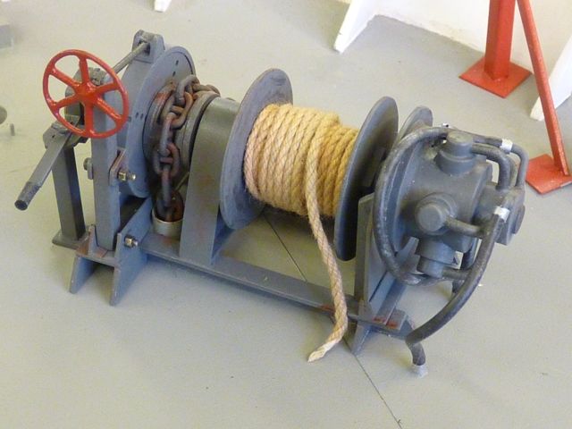
Participant@garethjones79649Another of those difficult dilemmas has now reared its head again on Shemarah – to do a major rework or not. Yesterday was a good day spent cobbling together the anchor windlass and winch from bits of scrap and coming up with quite a reasonable looking unit so far. Just got the brake and clutch to add on the right hand end.
That put me back in the mood for thinking how I could motorise the anchor. I have made provision for a drive unit under the deck and my original plan was to use a yacht sail winch. However I had two engineering requirements and had not worked out how to meet them. One was that I wanted the anchor to drop freely under its own weight and then be lifted slowly back up by the motor. Secondly I had to have some way of switching off the motor when the anchor was fully up.
Last night while sitting in the bath, fresh from my triumph with the windlass I had an idea how to achieve the first aim. Essentially the anchor chain would be pulled up either on to a drum or by a gypsy. The drum or gypsy would be driven by a small geared motor via a loose rubber belt and pulleys. A suitable servo would be positioned between the two pulleys. The servo arm would operate a microswitch and have a small idler pulley on it. To raise the anchor the servo arm would operate the switch and tension the belt so the motor drives the drum/gypsy. To allow the anchor to drop the servo arm moves away from the belt and microswitch. Basically the same mechanism in many a petrol engined lawnmower. Now I just need to work out how to stop the motor at the correct point (or so I thought).
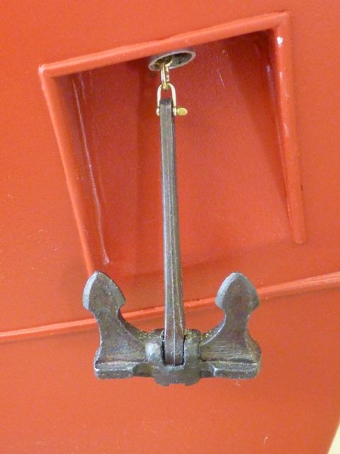
This morning bright and early I was in the workshop trying to work out the answer to the second problem, how to stop the motor at the right point. However it then dawned on me that the anchor recess was not correctly positioned in the hull. It was very difficult to work out the position from the drawing and photos when I first cut the recess. However I have now realised I should have applied a bit of engineering logic, not just tried to match the drawing. The top of the recess should have been horizontal and the anchor allowed to pull up squarely into it. On the drawing, and as I have made it, it slopes so the anchor sits at an angle to the recess in the hull, see the picture below.
So the dilemma is:-Do I leave it as is and just have a fixed raised anchor.
Do I cut it all out and start again doing it correctly and making some provision for a switch operated when the anchor is fully raised in the recess.
Do I just fix the anchor for now and hope I can come up with a solution that doesnt need a big rework in the future.
One further problem is that if I position the winch/windlass to match the current anchor position I will almost certainly have to move it if I rework the recess.
Decisions, decisions.
8 September 2012 at 08:24 #36370Gareth Jones
Participant@garethjones79649After watching the attached video last night (linked from another well known model boating website) I have decided that my anchor installation may not be that bad after all. Perhaps it just needs a bit of a tweak as to where the hawse pipe cuts through the deck. The recess in the side of the hull can stay as it is I think. The relevent bit of the video is about 11 minutes in from the start but the whole thing is quite interesting.
17 September 2012 at 18:42 #36552Gareth Jones
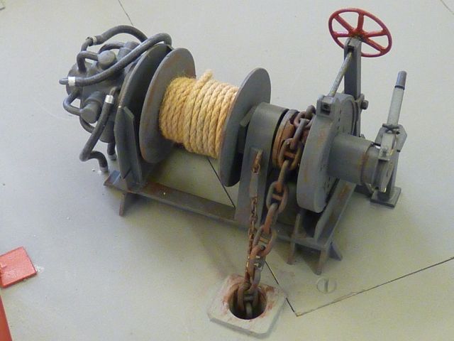
Participant@garethjones79649I decided to leave the anchor recess and hawse pipe where it is so I have finally glued the hawse pipe into position and fitted a reinforcing plate on the deck and in the recess. The winch/windlass is now complete, although the rope on the winch drum looks a bit too thick. It looked about the right size before I dyed it using my traditional method of boiling water and a Yorkshire tea bag. However its no big deal to replace it in the future. Ideally I would like to use a blue dye to simulate the typical polypropylene rope but blue food dye did not work.
The bitter end of the anchor chain is tied to an eye screwed into the underside of the access panel in the deck and the rest of the chain hangs inside the hull, awaiting the day when I make a decision on whether to motorise the system. The anchor is therefore just held up by the chain stopper 'devils claw' which you can see in the above photo just to the left of the main chain.
The remaining jobs to complete on the front end are the life raft container, a couple of pulleys fixed to the deck to run the cable to the A frame hoist and a few ventilators. I plan to start the rear gantry next as its the biggest remaining piece of structure and do the other small bits at the front as fill in jobs when I fancy a change.
-
AuthorPosts
- Please log in to reply to this topic. Registering is free and easy using the links on the menu at the top of this page.
Code of conduct | Forum Help/FAQs
Latest Replies
Home › Forums › Scratch build › Topics
-
- Topic
- Voices
- Posts
- Last Post
-
-
Lead Zinc boat parts Clean up, and Type of Glue to attach them
Started by:
bruce dixon in: Building Kits
- 3
- 5
-
4 hours, 50 minutes ago
bruce dixon
-
TID steam tug 42″ – PN Thomas drawing enlarged
1
2
Started by:
 Ray Wood 3
in: Scratch build
- 8
- 34
-
5 hours, 2 minutes ago
 Ray Wood 3
-
Aeronaut Mahogany Sheet issue
Started by:
floatmeboat2025 in: Beginners
- 4
- 7
-
5 hours, 7 minutes ago
 Ray Wood 3
-
Vic Smeed’s Silver Mist
1
2
…
33
34
Started by:
Bob Abell 2 in: Scratch build
- 5
- 833
-
5 hours, 12 minutes ago
 Ray Wood 3
-
Antique model lifeboat
Started by:
douglarse in: Gallery
- 3
- 8
-
14 hours, 31 minutes ago
 Richard Simpson
-
Antique lifeboat in auction
Started by:
douglarse in: Buy/Sell or Trade
- 1
- 1
-
1 day, 1 hour ago
douglarse
-
Melton & District Model Club 60th Anniversary Model Show
Started by:
Michael Campbell 2 in: Shows and Events
- 1
- 1
-
2 days, 9 hours ago
Michael Campbell 2
-
Fairey Huntsman 28
1
2
…
7
8
Started by:
 Chris Fellows
in: Build Blogs
- 2
- 197
-
3 days, 7 hours ago
 Colin Bishop
-
Building a hull.
Started by:
 mick east
in: Scratch build
- 7
- 16
-
4 days, 15 hours ago
 mick east
-
Fairey Faun
1
2
3
Started by:
 Chris Fellows
in: Build Blogs
- 7
- 60
-
5 days, 8 hours ago
 Ray Wood 3
-
superglue allergy
Started by:
 Alasdair Allan
in: All things floating
- 5
- 12
-
6 days, 9 hours ago
Tim Cooper
-
Model Yacht Racing – The future ??
Started by:
 Ray Wood 3
in: Sailing Models
- 4
- 4
-
1 week ago
 Richard Simpson
-
Vic Smeed’s Legacy
Started by:
 Colin Bishop
in: All things floating
- 6
- 15
-
1 week ago
 Colin Bishop
-
Eezebilt RAF Fire Boat
Started by:
Tim Cooper in: Build Blogs
- 4
- 9
-
1 week ago
 Colin Bishop
-
Feathered Friends
Started by:
 Chris Fellows
in: Soapbox
- 3
- 9
-
1 week, 1 day ago
 Richard Simpson
-
4D Modelshop
Started by:
Keith Long in: Scratch build
- 6
- 9
-
1 week, 2 days ago
 Colin Bishop
-
Fairey Huntsman 31
1
2
…
5
6
Started by:
 Chris Fellows
in: Build Blogs
- 14
- 139
-
1 week, 3 days ago
 Chris Fellows
-
John Cobb’s Crusader
1
2
…
7
8
Started by:
 Paul T
in: Scratch build
- 1
- 192
-
1 week, 4 days ago
 John W E
-
Complex Automata
Started by:
 Colin Bishop
in: Soapbox
- 1
- 1
-
1 week, 5 days ago
 Colin Bishop
-
RAF Fireboat ID
Started by:
 Dave Reed
in: Collectors’ corner
- 8
- 24
-
1 week, 6 days ago
Tim Cooper
-
Lady of Skye (puffer)
1
2
Started by:
 mick east
in: Build Blogs
- 9
- 43
-
2 weeks ago
 Richard Simpson
-
Todays Boating
1
2
…
210
211
Started by:
 ashley needham
in: All things floating
- 84
- 5,252
-
2 weeks, 3 days ago
 Colin Bishop
-
Sea Rover Restoration
Started by:
harry smith 1 in: Collectors’ corner
- 4
- 10
-
2 weeks, 3 days ago
 Richard Simpson
-
WORKSHOP LIGHTING
Started by:
 John W E
in: All things floating
- 9
- 18
-
2 weeks, 4 days ago
 Colin Bishop
-
Mayhem Website Down
Started by:
 Colin Bishop
in: All things floating
- 4
- 10
-
3 weeks ago
 Colin Bishop
-
Lead Zinc boat parts Clean up, and Type of Glue to attach them
-
Latest Issue
Newsletter Sign-up
Latest Replies
- Lead Zinc boat parts Clean up, and Type of Glue to attach them
- TID steam tug 42″ – PN Thomas drawing enlarged
- Aeronaut Mahogany Sheet issue
- Vic Smeed’s Silver Mist
- Antique model lifeboat
- Antique lifeboat in auction
- Melton & District Model Club 60th Anniversary Model Show
- Fairey Huntsman 28
- Building a hull.
- Fairey Faun


