RICHARD SIMPSON’s mini-series on model steam plants
For expanded captions for some of the photos go directly to the Album
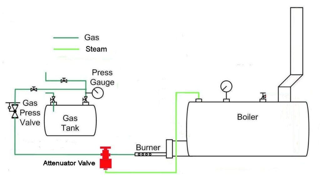
One particular area of model steam plants that seems to generate more discussion than most is the control of gas to the burner. There are a number of options available and a lot of modellers simply choose to use nothing, so I thought it would be useful to take one option, the Attenuator Valve, and describe its use and the reason for fitting it.
Enjoy more Model Boats Magazine reading.
Click here to subscribe & save.
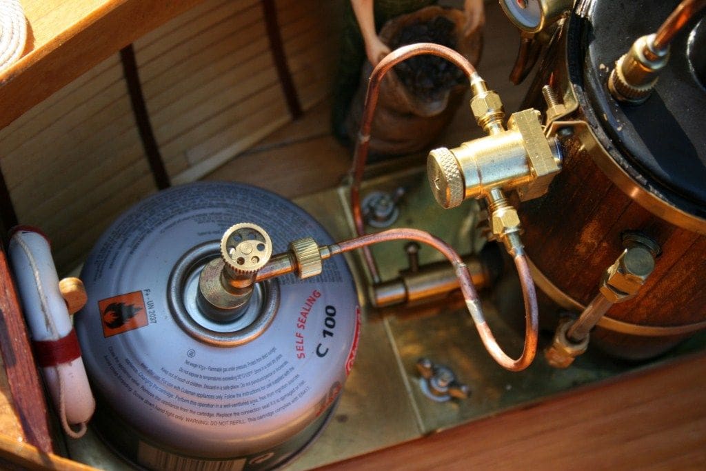
If you consider a gas tank in a model boat with a valve on it leading to a supply pipe and ultimately the burner, you will realise that you have very little control of the flame at the burner. This isn’t surprising as the valve on the tank is only an isolation valve as opposed to a proper metering device and so tends to be very crude at controlling the gas flow. You can change the size of the jet at the burner, but this of course requires dismantling the burner so is not a consideration for controlling the flame whilst the model is in operation. Consequently when you turn the gas on and ignite the burner that’s what you get and this is what you will continue to get as long as there is gas in the tank. This has the significant disadvantage of putting the same amount of heat into the boiler at all times, so when you are using the engine and therefore using steam, the pressure in the boiler will slowly fall until the engine will not run. Thus, you then have to wait for the pressure to rise again. On the other hand, if you leave the boat at rest on the water, the pressure will continue to rise until the safety valve lifts and you find yourself wasting gas and water, not to mention making a mess of your boat as the water is ejected from the safety valve. You can usually tell a model fitted with a burner with no means of control as they are the ones hammering around the pond as fast as they can go to prevent the safety valve lifting, and I know because I’ve been there!
There is also the disadvantage of the cooling effect of the gas tank being more of a concern as the gas is evaporating at a high rate continuously and so the gas tank invariably starts to cool, possibly to the point where the evaporation rate is affected. As I have already suggested, you can fit varying sizes of jet to try to match the burner output with the engine demand, however a significant improvement is to physically control the flame.
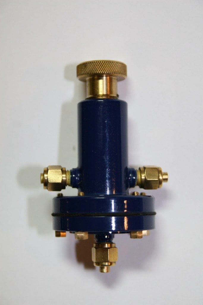
Attenuator Valve
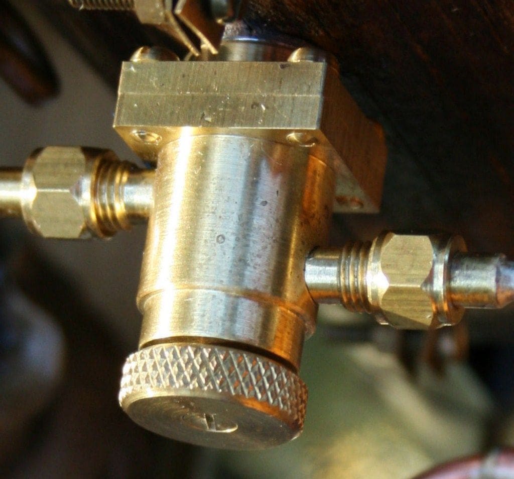
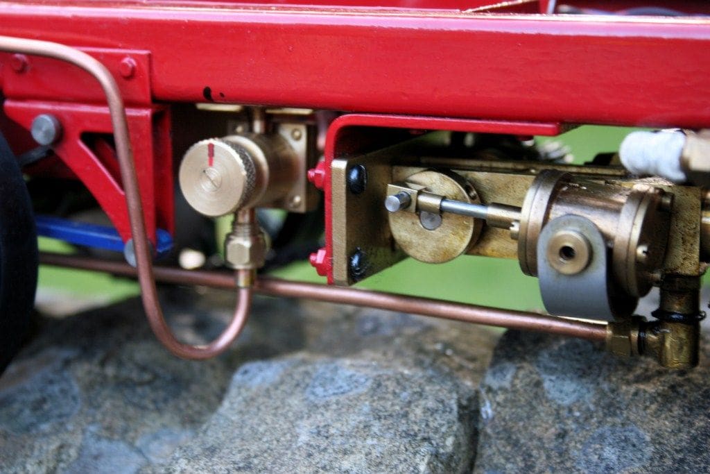
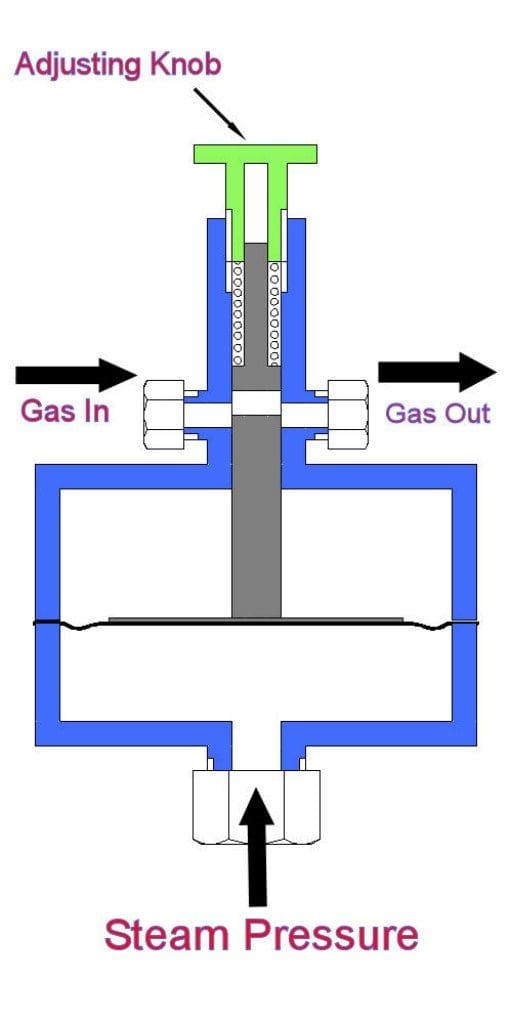
Of the various means of controlling the gas to the burner, probably the simplest and some would even say the most effective, is a well set up attenuator valve. The purpose of this device is to control the burner flame such that when the pressure in the boiler rises, the flame reduces and when the pressure in the boiler falls, the flame increases. This should stabilise the pressure in the boiler and prevent the challenges described earlier as well as ensuring a more consistent performance from the engine as it works at a similar pressure all the time. The valve, in its simplest form, consists of a diaphragm which is moved by boiler pressure and which in turn operates a sliding valve that operates against a spring. This valve controls the gas supply going through it dependant on its position such that, the greater movement of the diaphragm then the more the valve is moved and the less gas is allowed through. The diaphragm is connected to the steam space of the boiler so its movement is directly related to the pressure in the boiler.
Above the valve is the spring, which sits on a screwed adjuster. This adjuster increases or decreases the spring pressure and so varies the effective set point to which the burner will regulate. The valve is therefore plumbed into the system with the connection to the bottom of the diaphragm going to any steam space outlet on the boiler; the gas inlet connection goes to the gas supply and the gas outlet connection goes to the burner. The valve can be mounted at any position, however vertically would prevent condensate collecting on the diaphragm and possibly prolong its life. I have one connected directly on to the boiler itself and although the valve does get hot I am reliably informed by the manufacturer that it should operate successfully like this.
Set-up
To set-up the attenuator valve you first of all back off the adjusting screw completely and then fire up the burner. As the pressure in the boiler rises keep your eye on the pressure gauge and when it gets to the pressure level you want to maintain, you rotate the adjusting screw until you hear the flame turn down. You will then want to take the pressure up and down a few times to get a feel for just at what point the valve operates, both going up and going down, and you may then decide to further fine adjust the setting. When you are happy with the position, it is a good idea to mark the adjustment screw with either a spot of paint or a score mark so that you can return the setting to the same point if you ever decide to play around with the valve in the future.
Just by fitting this type of valve to your plant you will significantly save gas; have much more flexibility when operating the model; the power from the engine will be more consistent, plus you will not suffer the indignity of your safety valve lifting and spraying steam and water everywhere. If you do nothing else to improve the efficiency and ease of operation of your steam plant, then I would strongly recommend that you fit one of these valves. You really will be surprised at just how much they make steaming your model so much more pleasant.

