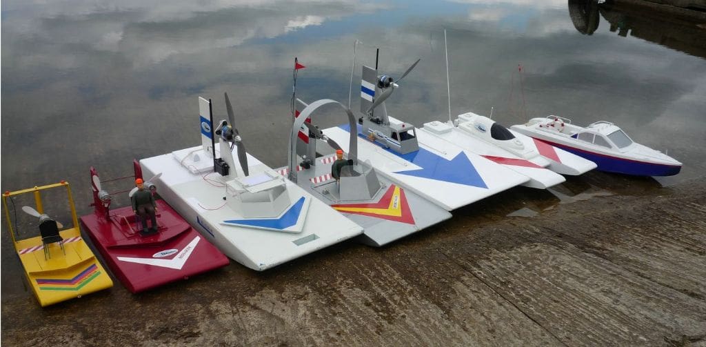
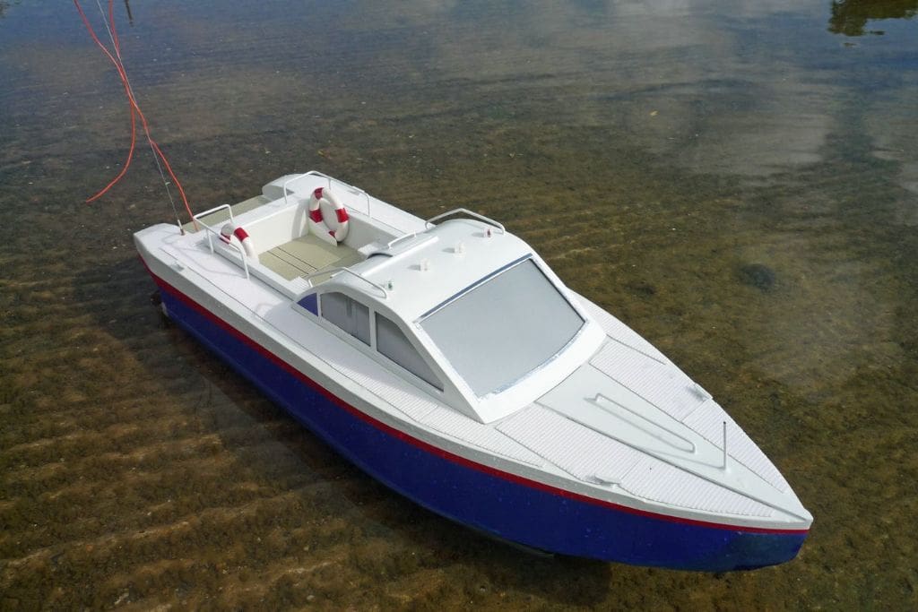
BRIAN JOHNSON presents a water jet powered semi-scale patrol launch
The concept
The combination of twin water jets in a conventional hull as a valid alternative to the Jet-Skim hybrid featured in Model Boats June 2010 was deemed worthwhile so it was off to the model shops once again for electrical gear and materials. The pursuit of power and minimum weight giving minimum immersion which was followed during a series of airboats now brought up the alien words ‘displacement’ and ‘ballast’ for any design using a conventional vee bottom hull. Having no knowledge or experience of conventional boats the only way was to literally start from scratch. At this time the question of the jet outlet being best below or partly above the static water level was still unresolved so below was decided on to enable work to start.
Enjoy more Model Boats Magazine reading.
Click here to subscribe & save.
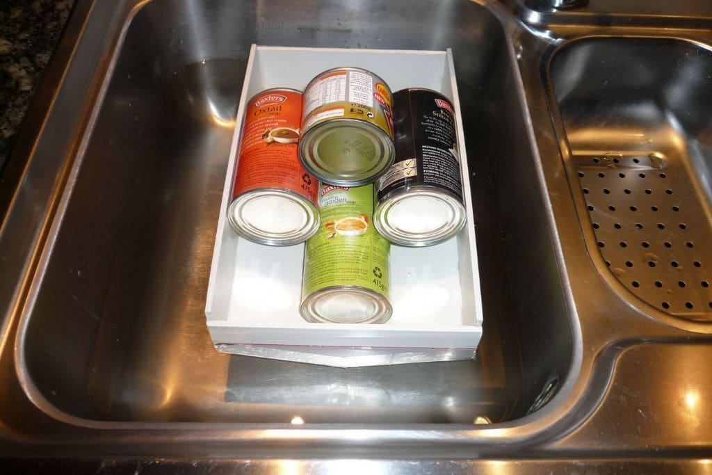
The relationship between displacement, i.e. weight and hull size obviously had to be settled first to enable the jet outlet to be somewhere near to the right level, so a dummy hull was cobbled up from spare 5mm plastic. This hull was 310mm long by 200mm wide by 90mm high on the centre line with a 15 degree vee slope at each side. The length was a copy of the Jet-Skim base plate before the curved underside was added and the width was thought to be the minimum required to take two jet units. A red line at 30mm down from the top represented the proposed static water line. Five x 475 gram cans of soup plus the hull weighing 340 grams, gave a total of 2715 grams and immersed the red line by 3mm. Replacing one can by a smaller can of 235 grams gave a total of 2475 grams and brought the red line and the water line spot on together with a wetted area of 620 sq. cm. Having established what seemed to be a reasonable basis for actual work the wetted area was the first target. The assumed weight would be similar to Jet-Skim with an extra drive unit weighing 475 grams giving a projected total of 2755 grams and an increase of plus 11.3% over the dummy results, this equating to 690 sq. cm. wetted area and a width of 220mm. The only known items were the weight of the electrical hardware at 1675 grams and the dummy weight of 340 grams. These together gave a red line flotation level of 10mm above the water level and it took another large can of soup to submerge it to the design level. Obviously the hull front portion would provide further buoyancy and weight, but a width increase to say 240mm was thought safer even at the risk of ballast being required. All this seems a long way round but it helped to settle the mind and produce some feasible figures.
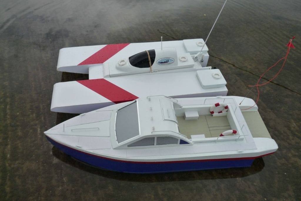
While working on the dummy, thoughts of what a vee hull model could look like were becoming necessary and the Castoldi Jet Craft website helped provide the answer. Being a water jet version, their Vector 21 was ideal as a basis for my model. It is a single jet boat, but fitting twin jets was not thought to affect it in any way and at around 1:10 scale suited well my proposed model, except that 90mm was added to the length to allow more room for the internal gear.
Building
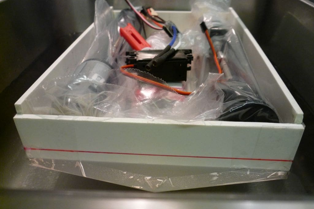
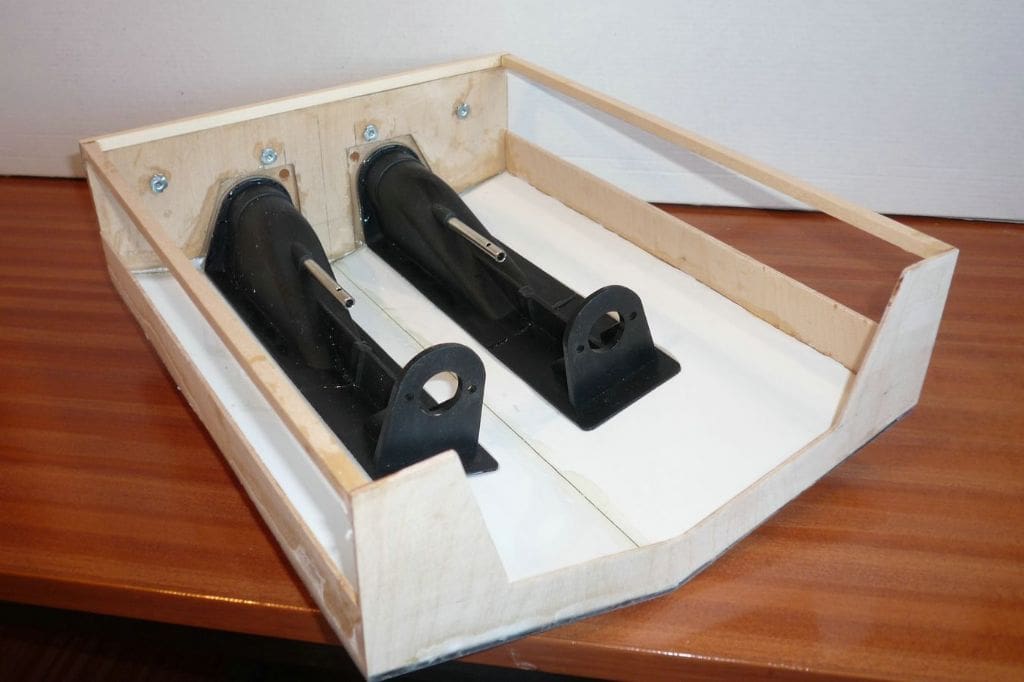
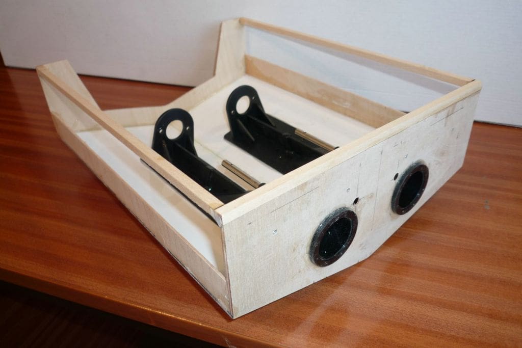
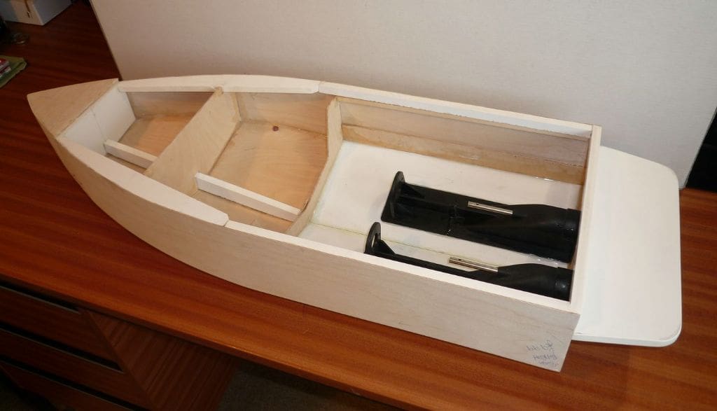
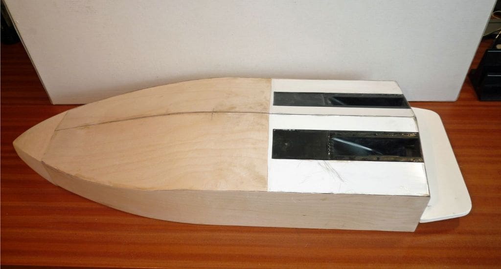
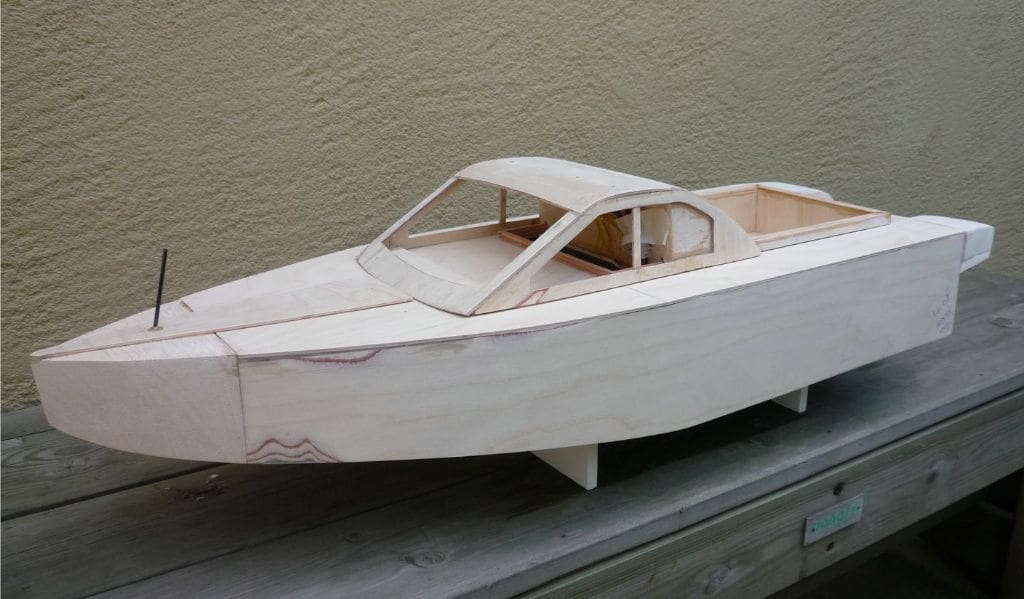
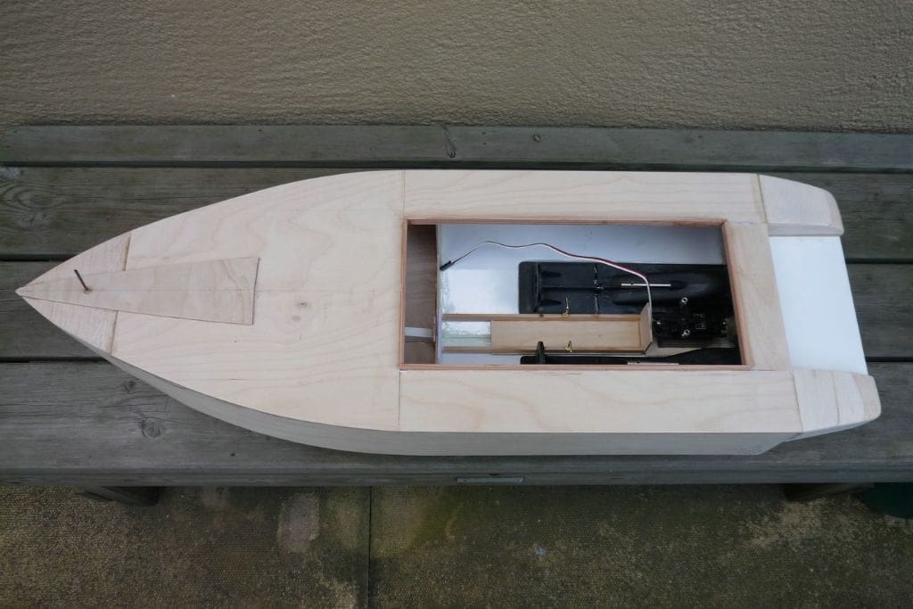
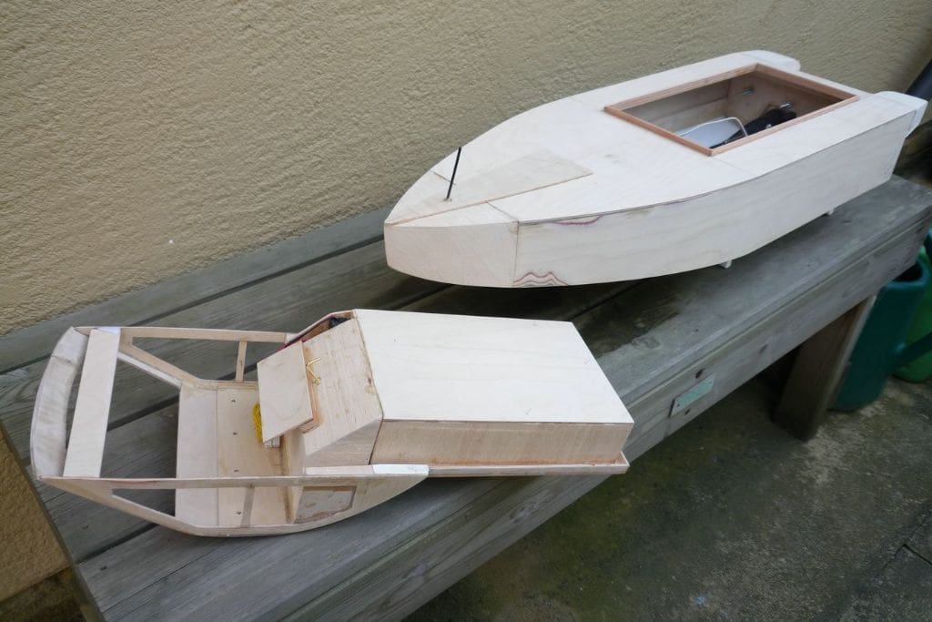
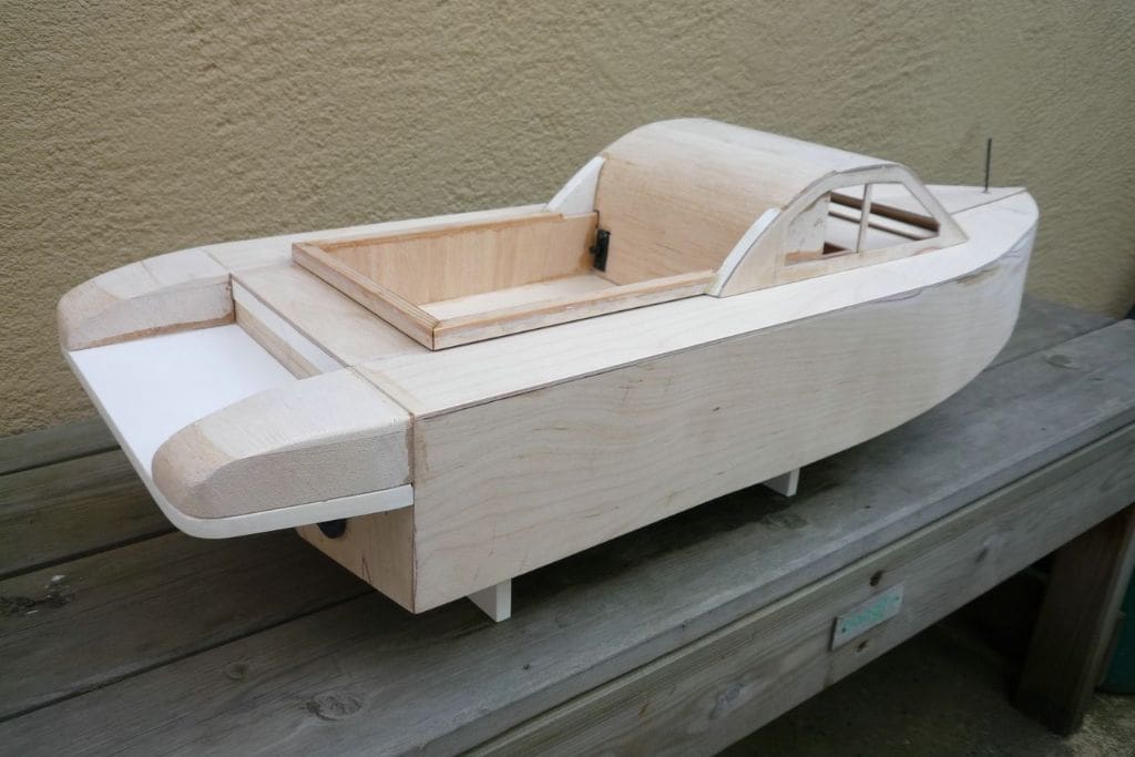
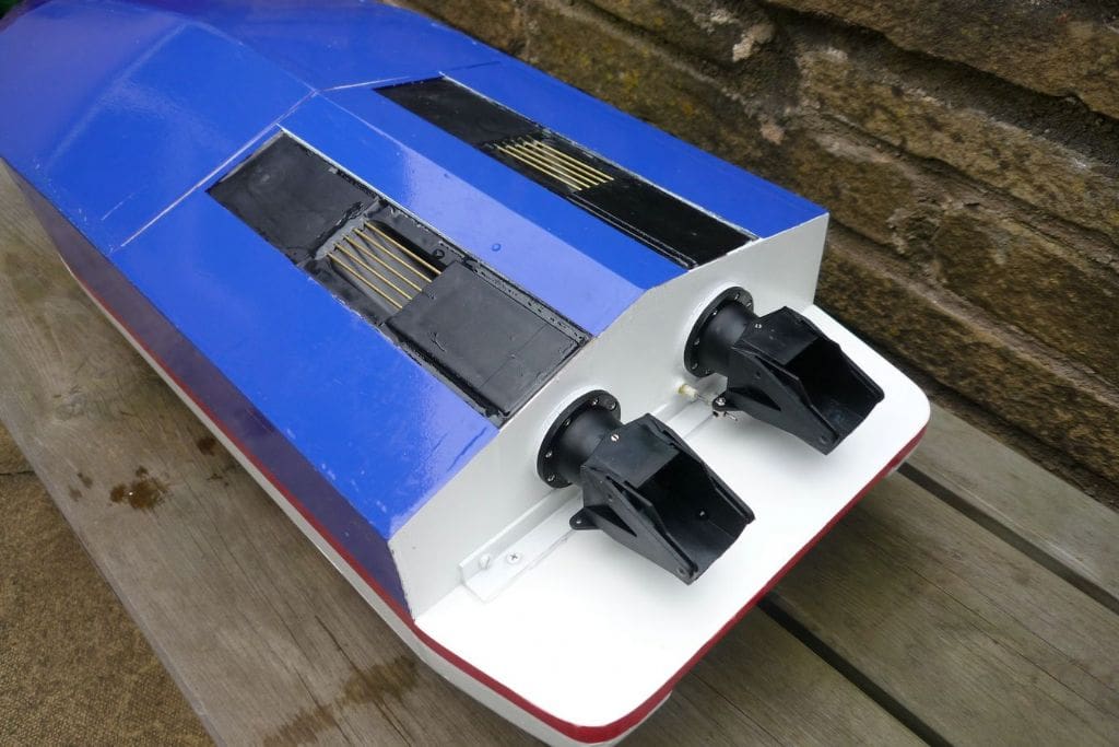
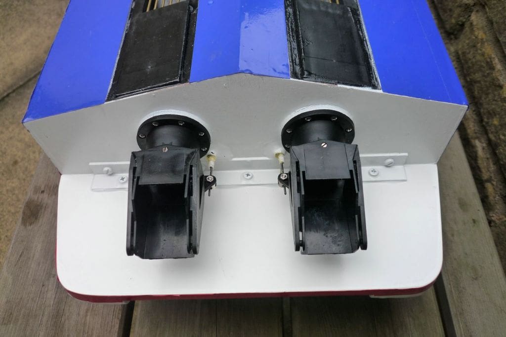
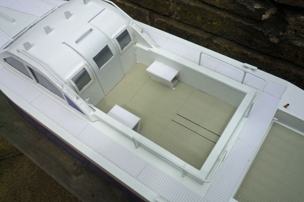
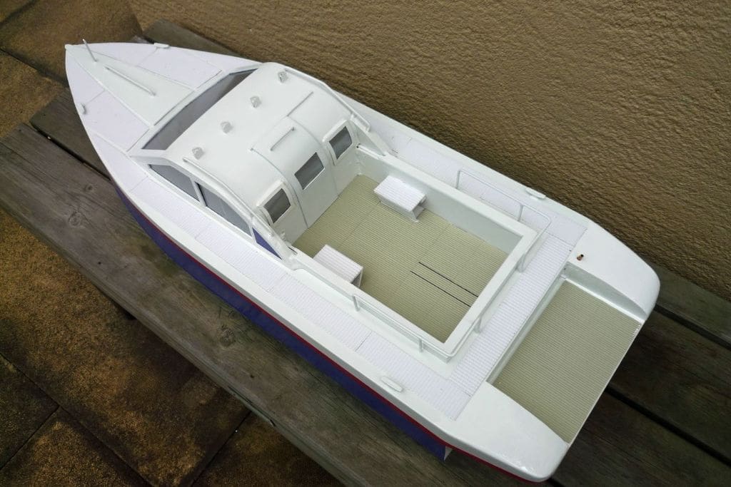
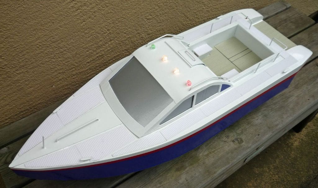
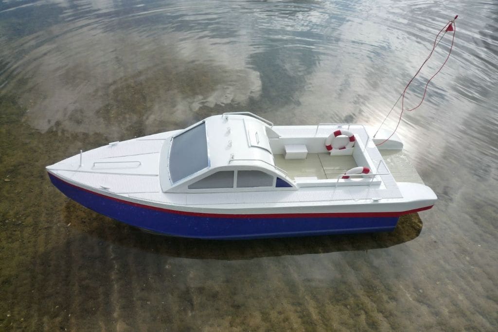
By now, being used to handling the dummy hull, the idea that a similar box to carry the two Graupner Jet Propulsion Unit 6 drive units, with a curved front extension to form the prow, would be easy and quick to make. Drawing on the Jet-Skim experience a 3mm thick aluminium composite base plate (although plywood would equally be suitable) was made 300mm long with slots for the drive intakes and in two portions which when butted together with a 15° slope on each gave a hull width of 244mm. A front 2mm plywood cut-away bulkhead and a rear one notched to clear the drive unit flanges along with top and bottom side rails completed the box. Using epoxy resin the drive housings were fitted and all joints fully sealed. The materials available to make the model were 2mm plywood, sheets of 0.8mm birch plywood for the curved cladding, 9mm thick plastic (as used for window sills) which provides a good adhesive area for various joints and five minute or 30 minute epoxy resin. To make the front extension the box was upturned onto a flat area and made secure using stops and masking tape. A front plastic bulkhead 115mm wide x 60mm side height and shallow base vee was fixed at an arbitrary 575mm from the stern and the two base skins cut and fitted from the front of the drive slots to the bulkhead giving a good lapping and gluing area on the box base. Cornflake packets helped to determine the side profile and the central tapering but it was not critical as the epoxy filled and strengthened this long joint. Having the level top and curved bottom established, corn flake packets wrapped along the side from the stern to the front bulkhead allowed a pencil to copy the curve of the bottom sheet and provide a template for the 90mm wide full length side sheets which were then glued on to the box, bottom sheet and bulkhead. Plastic strips were profiled and fitted to the sides and stern to support the deck and one fitted at the curved central keel joint for stiffening and extra sealing. An intermediate bulkhead was then fitted, and thoroughly glued in place between the box and front bulkhead for more strength and a 95mm long shaped balsa nose cone brought the length up to 670mm. After a stern outer facing of 0.8mm plywood with two holes for the jet outlets was fitted, the 80mm long plastic fender was shaped and positioned using screws and glue and the side fairings then glued on and sanded. All sheet edges and joints were trimmed back, sometimes right through to the plastic or epoxy behind, and further epoxy added to any suspect or vulnerable areas. The hull, still without a deck, was now looking something like a boat, but a check was needed on its developing weight and its possible flotation level before it was too late to take remedial action. With all the electrical gear the total weight was 2435 grams so it was wrapped in a bin liner as closely as possible for the truest reading and placed in the bath. The deck line was horizontal and the water level was 10mm below the outlet centre line which was good. The addition of a deck and cabin etc. would give more immersion, but obviously weight was not a problem so these could be made quite robust. An aperture of 285mm x 135mm at 40mm from the stern of the 665mm x 246mm x 2mm plywood deck sheet allowed good access to the gear and a coaming was fitted to help stiffen and seal the aperture, this completing the basic hull. The integral cabin and well deck was a little tricky, but the three-sided well with its coaming cover was glued to a shaped balsa block forming the rear of the cabin. The rest of the cabin was then glued to the block. The window apertures were left open but overlapping plywood blanks were made and covered with silver grey vinyl sheet ready for gluing into position later, as were the rear windows and sliding door. The addition of the two steps and 2.4mm brass rod handrails left the whole unit ready for painting. After sealing the plywood and balsa with 50/50 dope and thinners the cabin and hull top and sides were primed and finished white with blue vinyl and a red stripe.
So the final dimensions were:
Overall length: 740mm
Hull length: 660mm
Beam: 246mm
Fitting out
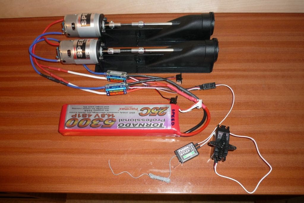
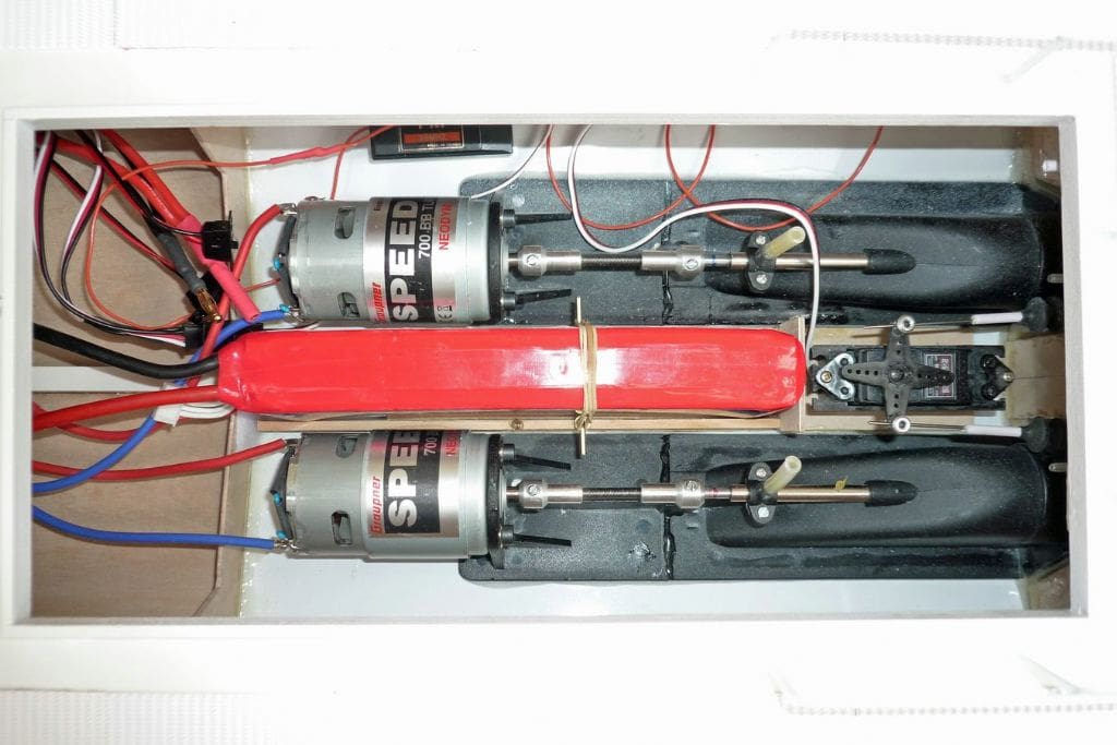
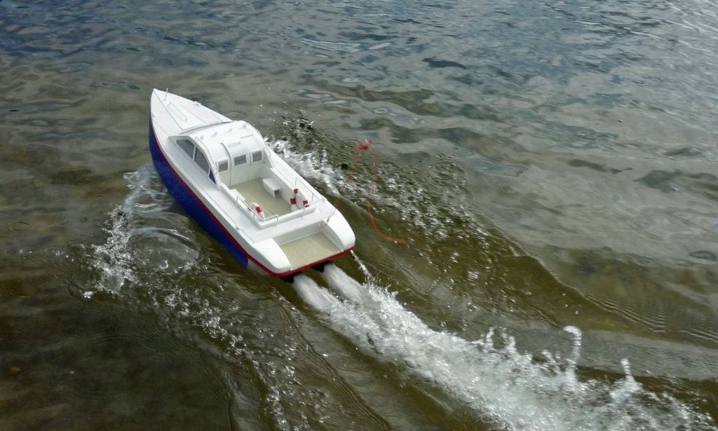
The main items required are two Graupner Jet Propulsion Unit 6 Water Jets with steering nozzles, motor mounts, torsion type couplings and Speed 700 BB Turbo Neodym motors, four cell 14.8v 5300mAh 25C LiPo battery, Futaba S3152 servo with a matching cradle. Also needed was a receiver (only two channels are required of the six channel actually used) and two 50 Amp controllers. The reversing buckets have not been fitted as their main use is in larger and slower models and would give little benefit in this type of model. The steering servo sits between the water inlet ducts and the twin lever rods operate the steering nozzles through bellows and plastic sleeves to keep the water out. The long battery takes up the rest of the length between the inlet ducts and is retained by stops and side hooks with elastic bands. The controllers and cables make their own space in front of the main bulkhead and are of the non-marine type for which there is no valid reason! A short length of plastic sleeve allows the aerial to pass through the stern to the removable wire mast. The 6v navigation lights on the cabin are powered by a separate six cell battery under the roof and operated by a switch under one of the rear windows. The deck walkways are the hard side of heavy duty Velcro, with its own weatherproof adhesive. The plastic well and rear fender decking is by Wills Kits, item number SS MP 219 which looks well, needs no painting and is actually model railway 00 Gauge Scenic Series corrugated asbestos. The ‘during construction’ weight of 2435 grams had increased to 3510 grams when completed, including the cabin with battery of 530 grams, and the flotation level was still acceptable at just above the outlet centre line. The Graupner Unit 6 Water Jet was designed for the Manhattan 74 Motor Yacht and when featured in a previous MB build article it proved to be fast and satisfactory using their standard Speed 700 BB motors with a model finished weight of 7kg.
Performance and conclusion
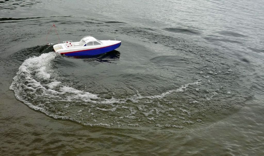
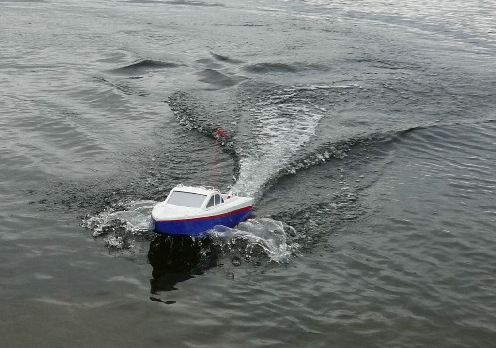
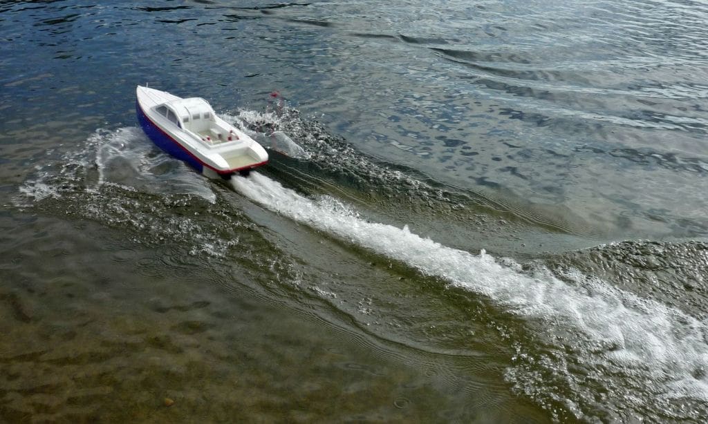
This Vector 21 model weighing only 3.5kg and using the more powerful Speed 700 BB Turbo Neodym motors has a performance that exceeds all expectations including instant turning without any loss of stability. Maximum speed tests will gradually follow and the bow wave patterns will become established but even at cruising speed the whole wake looks impressive.
So this is the story so far that started off with Glynn Guest’s airboat skimmer Free Plan back in September 2007. Where I go from here I am not sure, but as they say: ‘Watch this space!’
(This model is a development of Jet-Skim, itself a spin-off from Brian’s sequence of airboats. For reader’s interest, in February 2008 MB, Brian had a letter published in Mail Boat about his airboat development of the original Glynn Guest Skimmer Free Plan first published in September 2007 MB. This was then followed by his excellent practical in depth articles in the July 2008, November 2008, May 2009, September 2009, January 2010 (Skim-Pack and Speed-Skim) and June 2010 (Jet-Pack and Jet Skim) issues of MB. He is to be congratulated on his practical, well thought out and described developments from the original Skimmer design – Editor)