With profuse apologies… Due to a technical glitch, the explanatory diagrams featured on page 46 of last month’s issue failed to print in their entirety.
Sincerest apologies, therefore, if you found yourself trying to make sense of things! To set the record straight, here are the diagrams as they should have appeared, along with the copy that relates to them…
Volts find breaks
The first example of where a multimeter might ‘save the day’ is when you switch on and nothing happens.
Enjoy more Model Boats Magazine reading in the monthly magazine.
Click here to subscribe & save.
Taking a simple electric motor/speed controller/battery setup that you might find in a model (see Fig 1), the first thing to check is the battery, which can be done by placing a voltmeter across the terminals of the battery (as illustrated in position V1 of Fig 2). A lower than expected, or even zero, meter reading has already located a problem! Trying to sail with flat batteries must be one of the most common operational problems in this hobby. Few will not have heard the plaintive cry of “But I only charged them six months ago” from a distressed model boater. Just a reminder, if your speed controller uses a BEC (Battery Eliminator Circuit) and this battery is flat, then nothing in the model will work. If it gives the reading that you expect from a fully charged battery, then the fault lies elsewhere.
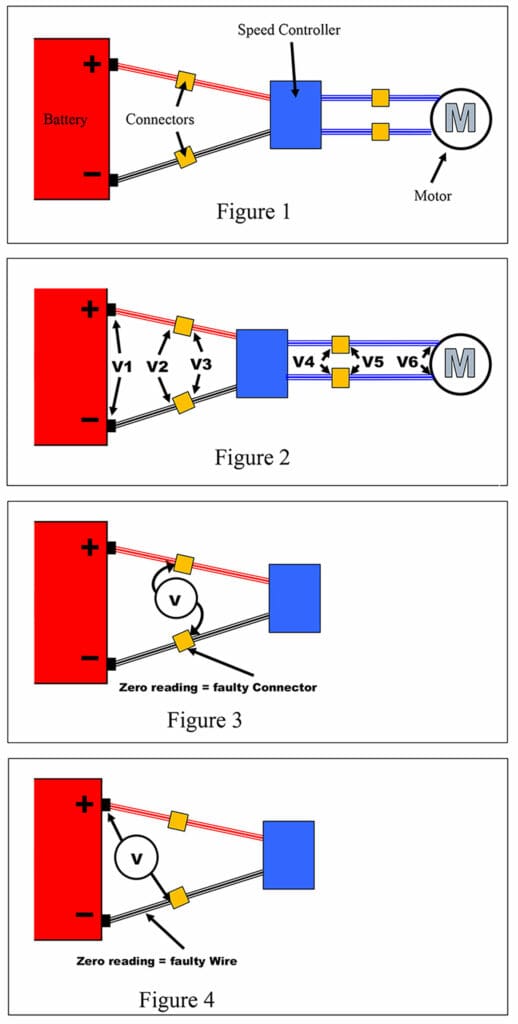
In this circuit there are a further five positions to check with a Voltmeter. Some care is always needed to ensure the meters probes do not touch and create a short. Working from the battery towards the motor, the first zero meter reading will tell you where a fault lies, as described in the table illustrated. Note that voltage checks at V4, 5 and 6 will require the speed controller to be operated by the R/C system.
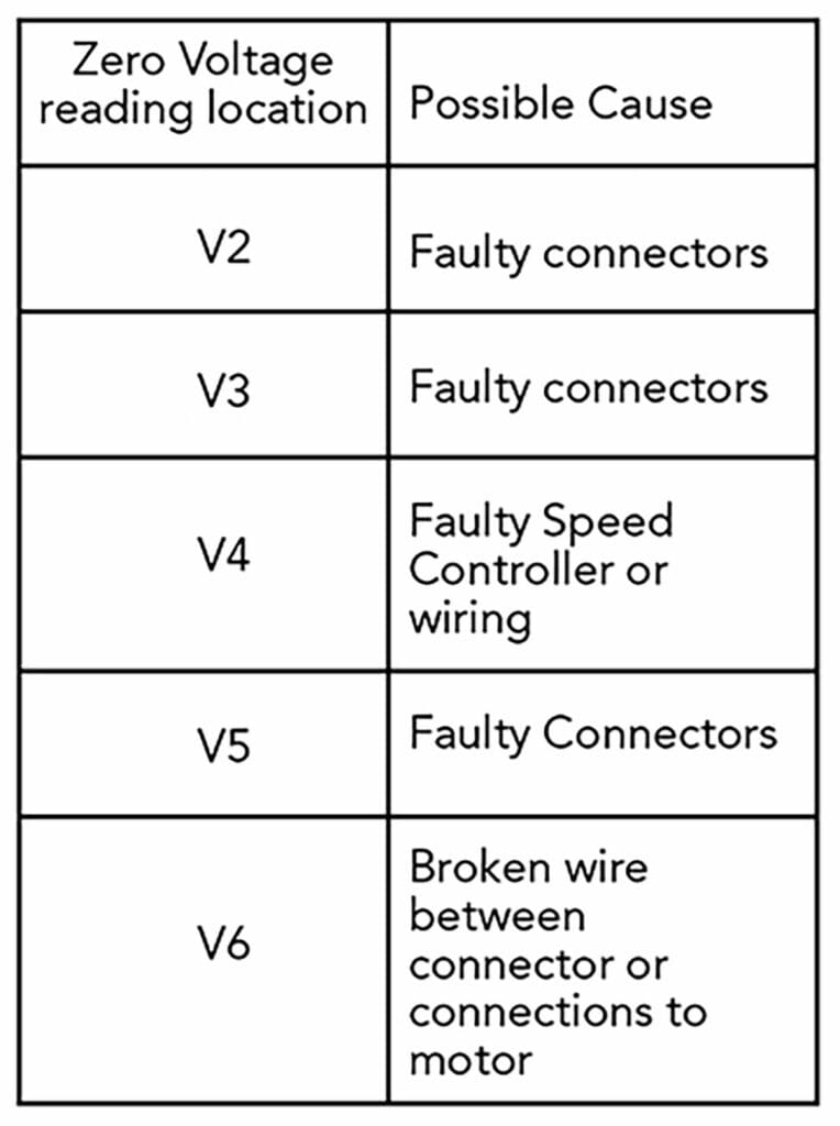
With brushed motors, the V6 reading requires placing the Voltmeter probes on the two motor terminals. If they show a voltage but the motor fails to turn, then disconnect the battery immediately. Somehow, a voltage is getting to the motor, and it may be converting electrical energy into heat, possibly lots of heat, which is never a good thing. You need to find out why it is not turning. Is the motor faulty? Or is the driveline jammed at some point?
I confess to not knowing how you would use a Voltmeter to check a brushless motor with three wires going from the speed controller into the motor. But, if any motor looks or sounds distressed and is not rotating, the advice is the same, switch off immediately!
Suspect connections
The meter checks in Fig. 2 might not be able to provide the exact location of a faulty connection. For example, a good result at V2 but zero at V3 does not tell you which connector has failed or whether both have.
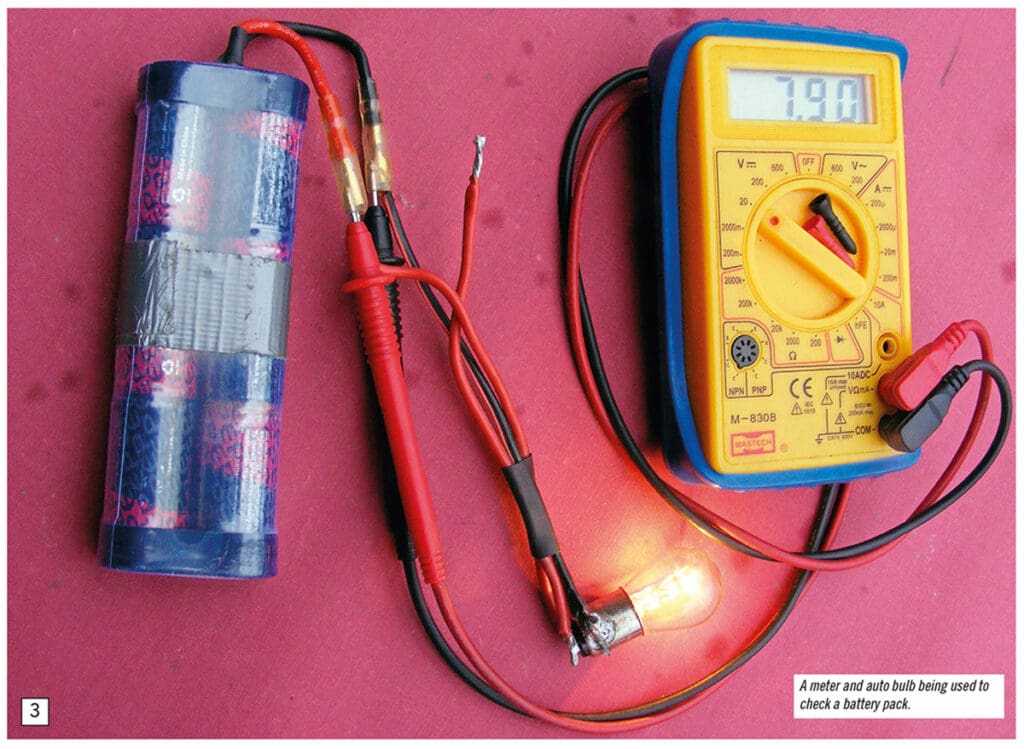
Individual failures can be found by placing the meter probes between the input side of one connector and the output side of the other (see Fig. 3). A zero reading tells you that the faulty connector is the one to which the meter probe is in the output side. A meter reading of the expected battery voltage suggests it is the other connector that has failed. But it is still worth checking by reversing the meter connections. Who knows, both might have failed?
It is possible that the wires going into and out of a connector are loose. Maybe the contact surfaces within the connectors are dirty or damaged. Some enthusiastic ‘jiggling’ of the wires can restore life into a model, but this rarely a wise thing to rely upon. These kinds for faults can reappear at any time, often at the worst possible moment. Replacement of anything suspect is usually the safest, and in the long term often the cheapest, solution.
Broken wires
Without X-ray vision, breaks in wires cannot be seen due to their coat of insulation. They can, however, be located in a similar fashion to that previously described. Going back to Fig. 2 and assuming that V1 reading is fine but V2 is zero, then it suggests that there is a break inside either wire going from the battery to the first pair of connectors. This is done with a meter probe on one battery terminal and the other on input side of the connector not joined to this battery terminal (see Fig. 4). A zero reading indicates that the wire between the connector and battery terminal has failed. Again, it is worth swopping over the meter probes just in case both wires have failed.


