TERRY LAWRENCE builds a 1907 Scottish Zulu fishing vessel
 [header].jpg)
When thinking of a static display model ship, many people think first of a hundred gun man-of-war and secondly then abandon the thought of a scratch build as a subject too difficult. Well yes it is, but you don’t have to start at the top and a little experience at the lower end will give pleasure and satisfaction and can lead to more ambitious projects later.
Enjoy more Model Boats Magazine reading.
Click here to subscribe & save.
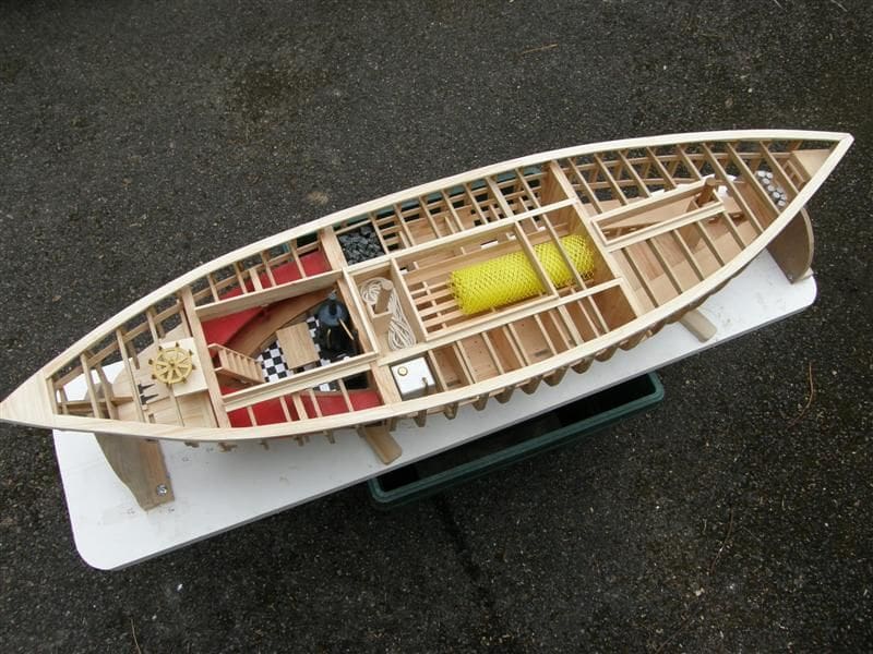
I have built fairly complex models before and put a lot of thought into the possibility of scratch building. Partly this has to do with cost and I will return briefly to this point later. However, the fun I anticipated had largely to do with creating a model where I could provide the timber in the right sizes in my own workshop; where I had freedom to vary construction a little if I wanted to, and above all to be able to display in a simple model the beauty of the internal construction, including the deck timbers and the fitting out of the various compartments.
For those of you whose interest may be whetted by this article, the first priority for me was to obtain plans and I wanted these to show not just the positions of the frames, but also their actual shapes.
Plans
Many kit makers, particularly the Italians, sell their kit plans separately, but these don’t show the frames at all (their kits use bulkheads only). Plans are available from the National Maritime Museum at Greenwich and in America from Harold Hahn who is a very experienced modeller, but he won’t accept credit cards.
His plan sets do show all the frames, but all measurements are imperial and not metric, which can be awkward if you are buying your timber. There are fine books to help with a couple of his models, but they are expensive. The four ‘practicums’ written by Father William Romero which cover the construction of the hull of HMS Warrior cost $340 alone (£250 + VAT + p/p at the time of this writing). So, I settled on Brown, Son and Ferguson of Glasgow, tel: 01414 291234, who advertise regularly in this magazine. Their catalogue of 70 plan sets by Harold Underhill proved to be just what I needed. They don’t give scale frame patterns, but do give hull lines from which they can be drawn and also cross-sections at various points. From this catalogue I chose a simple all timber, non-motorised fishing boat of 1907 at 1/24 scale, giving a model length of just over a metre. The full set of plans comprises six sheets, but for my model with no masts, spars or rigging, I needed only four sheets. These covered hull lines, profile, deck plan and details, construction plan and cross-sections. They cost £9.25 each plus VAT.
Timber
The next decision concerned the wood. Should I buy in, or cut my own? I needed about 100 feet or 33 metres just for the frames and I sought quotes which was a shock. One supplier, who did not even offer the species I wanted, quoted over £300! For this money, or less, I could buy a thicknesser and machine my own, which is what I did. Although I had once entertained thoughts of building in boxwood, this comes only in small and expensive dimensions.
I had been given some short lengths (450mm or so) of American straight-grained oak left over from a neighbour’s house extension, which I paid for with a wood carving for their new room. The thickness was 35mm, which partly dictated my method of frame construction. Although it had non-scale grain, it looked good, smelled good and was strong and free of charge. All my softwood came from scrap 4 x 2in rescued from skips.
Tools
This is the downside, if you have never done any woodwork. However, for the last fifteen years I have been active in woodwork and have collected some decent equipment for my workshop. For this model, I used three saws and a thicknesser. A cheap 10 inch TCT blade table saw ripped the oak into 3mm slices. A Proxxon miniature thicknesser was perfect for finishing each plank to 2mm, and an electric scroll saw cut each frame blank to the correct shape.
Measurements
Despite the original vessel being built of imperially sized timber as reflected on the plans, I decided to measure everything in metric. Apart from avoiding daily conversions, it is easier in millimetres than sixty-fourth’s of an inch. In any case, my thicknesser is precise. One turn of the depth setting represents 1mm, so it is easy to work to a quarter millimetre.
Plotting the frames
Drawing the frames for this Zulu-type fishing boat (her name was Muirneag) is achieved using the lines drawing (Sheet 942). The method is described in full by Harold Underhill in his book ‘Plank-on-frame models -Volume One’, pages 7 to 10 inclusive and I urge you to obtain this book which is still available from Brown, Son and Ferguson. The drawings throughout are very clear and very helpful. Once I had studied the plans, I was apprehensive about some aspects of the vessel’s design.
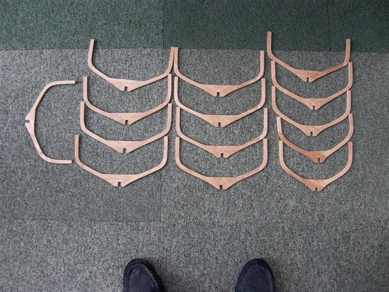
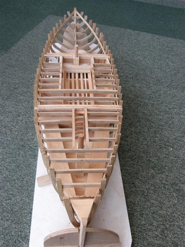
First, there were an awful lot of frames; 58 if you put them all in.
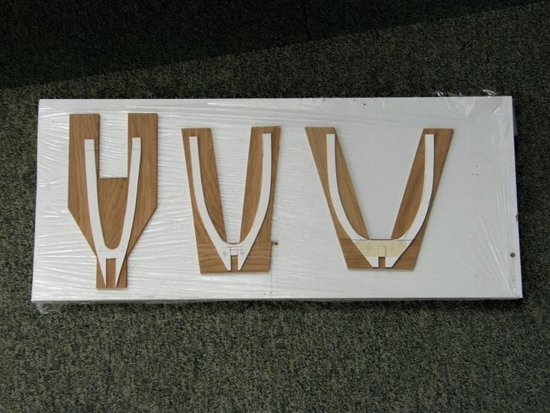
Second, there were four types of frame: U-shaped pieces amidships, frames fore-and-aft with curved sides which were bolted to floors, cant-frames at bow and stern which were not at right-angles to the keel and hanging frames with no floors. These last mentioned were placed between the main frames to support the planking.
The making of a main frame involved exact cutting and assembly of at least five curved components, each jointed and bolted (or dowelled) together.
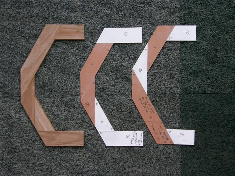
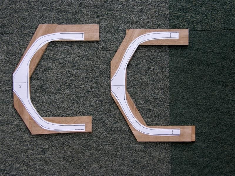
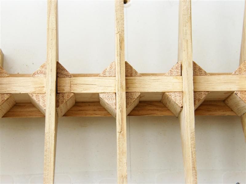
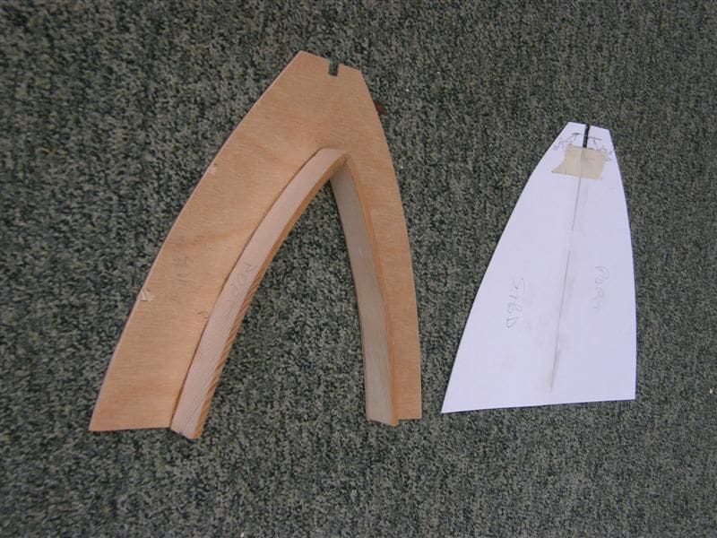
Straight away I wanted to modify the construction. First, I decided to omit all hanging frames. Without any connection to the keelson or their adjacent frames, they were redundant as I wanted to omit the planking. Next, I decided to make all frames double, for strength. Third, I decided to make the fore and aft bolted frames in the same way as for the centre section ones. Fourth, I found that I could omit the cant-frames without detriment. For someone who started out with the intention of copying the original exactly, I had already made, with many qualms, a lot of changes. For purists, my changes are almost sacrilege; for model makers they may be considered practical. Each frame of my model comprises two U-shaped frames each 2mm thick and of five butt-jointed components. Then the two thin frames are sandwiched together so no joints match and this gives a strong 4mm thick main frame. I was able to make card templates for the sections, using only angles of 45 and 60 degrees. Just glue onto this frame your paper drawing, and cut out the shape on the scroll saw. One frame shape covered all the mid-section frames, though you will need to modify the templates for frames forward or aft of these.
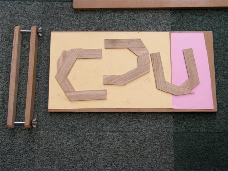
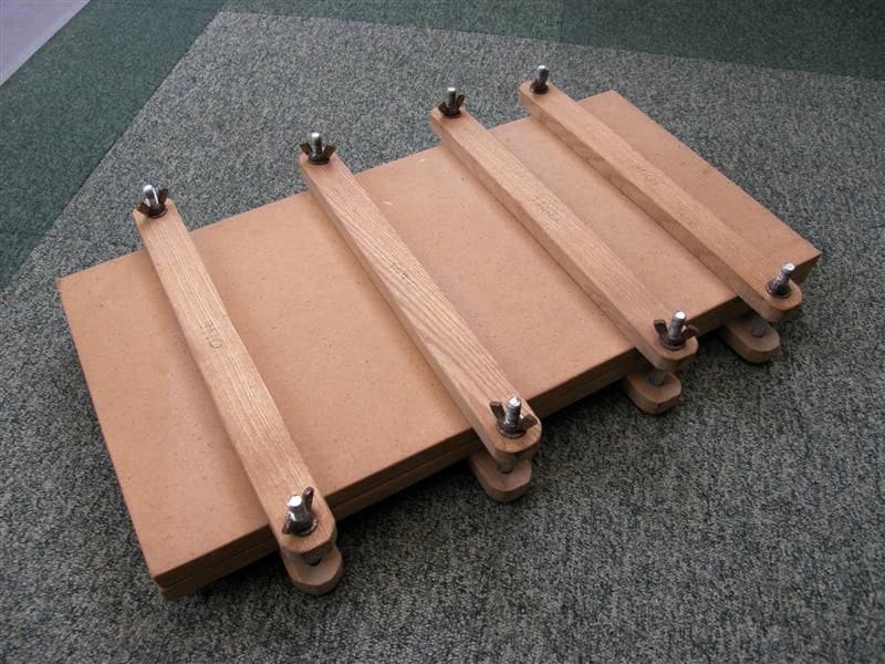
I used my home-made veneer press when gluing the pairs of frames together, as I found with the first attempt that without weights or press the two sections peeled away from each other, leaving a gap all round. This failed piece was thrown away.
The pictures show how simple the press is. It is of two sheets of 19mm MDF, 300 x 600mm, with pairs of crossbars of 20 x 40mm ash, the upper bar of each pair slightly convex. When the bolts with butterfly nuts at each end of the pairs, are tightened, the bars will lie flat and give equal pressure all along their length. I used a sheet of blotting paper above and below the glued pairs of frames, and found that the press would take four full frames at a time. When fully dry (overnight was safest) I stuck a paper template on each frame with a Pritt stick, and cut it out with a No.5 blade at medium speed, 850 to 1000 rpm, on the scroll saw.
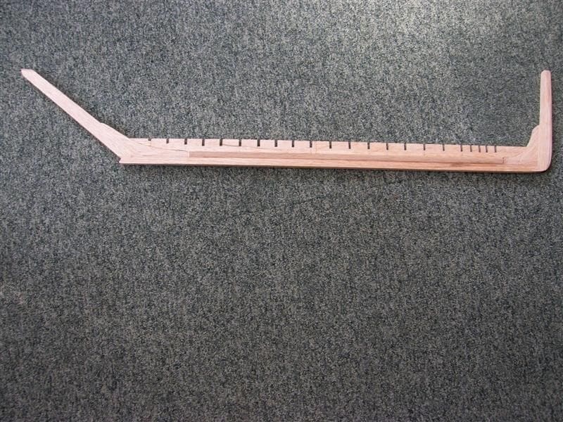
Keel and keelson
Taking dimensions direct from the plan, I needed oak 13 x 11mm for the keel and 25 x 8mm for the keelson. As the plan didn’t show width variations for the latter, I kept it at 25mm for the whole length, as I could always fair it into stem and sternposts later. I prepared some oak to 13 x 11mm, making sure I had enough for not just the keel, but also for stem and sternposts, fore and aft deadwood and apron. I took photocopies of these assemblies and glued them to the prepared timbers. The angles for the deadwood had to be precise, and this was best achieved with a disc sander after cutting out on the scroll saw. Harold Underhill in his book lays great stress on dowelling every joint and goes into great detail as to how to make a steel drawplate and using it to reduce split bamboo to very small dowels. I found all this daunting, but did try it when assembling the spine of the vessel on a flat surface. I used 2.5mm bamboo dowels to join keel, keelson and deadwood. However, things have moved on since Harold wrote his stuff (1958) and I find that waterproof PVA white glue to be superbly strong without the need for dowels.
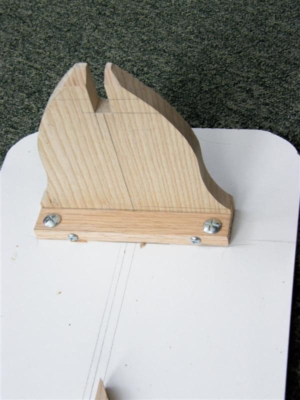
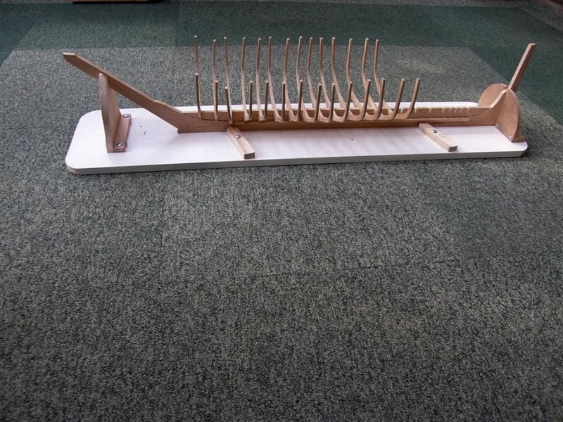
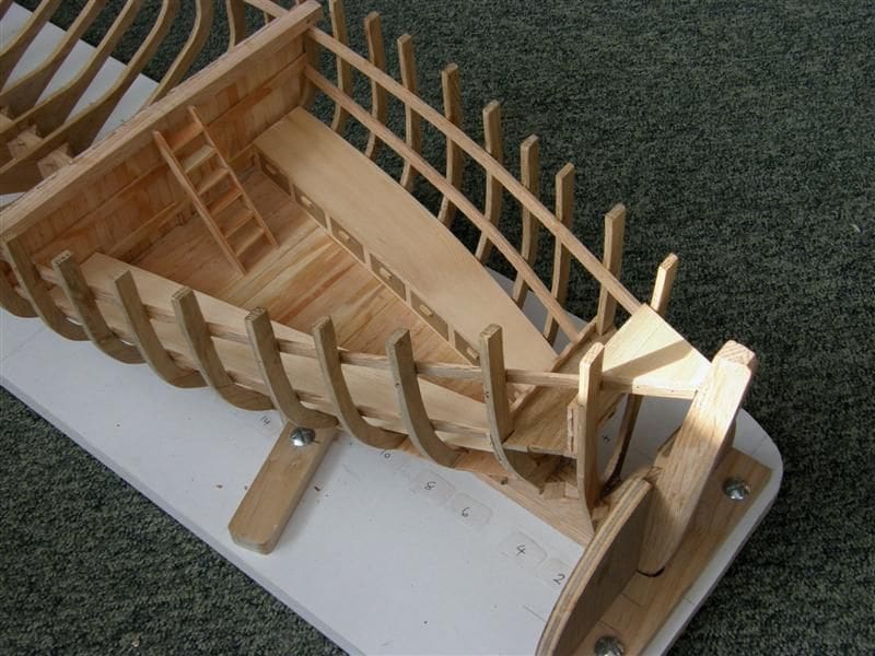
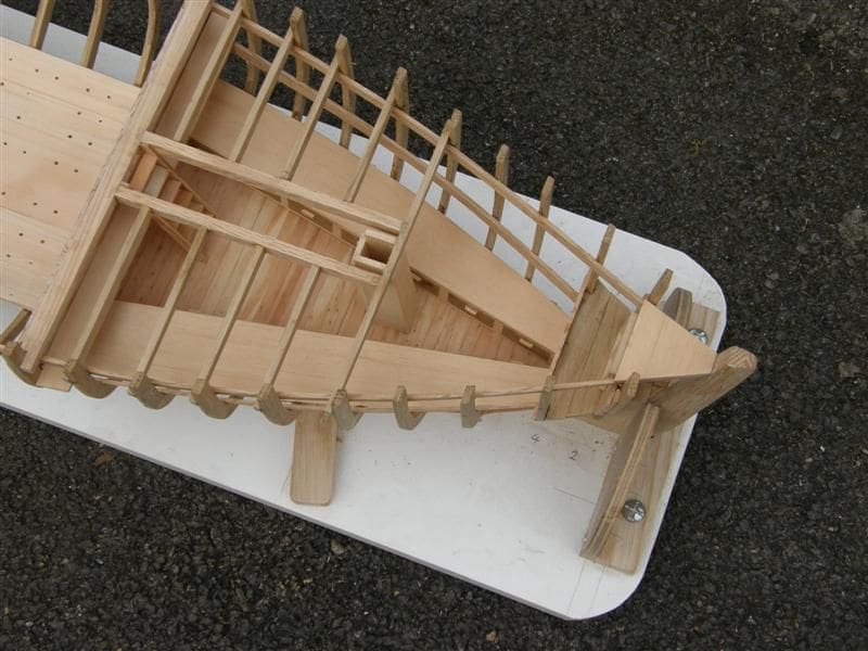
Building board
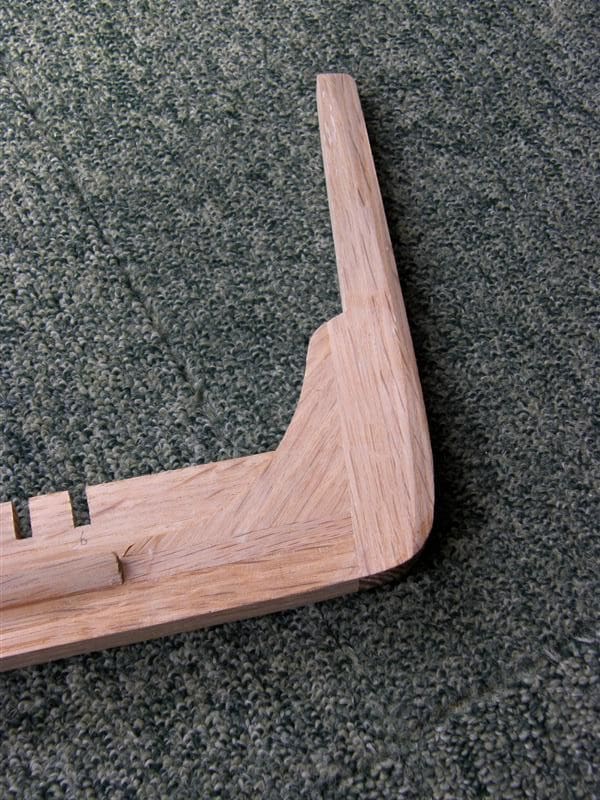
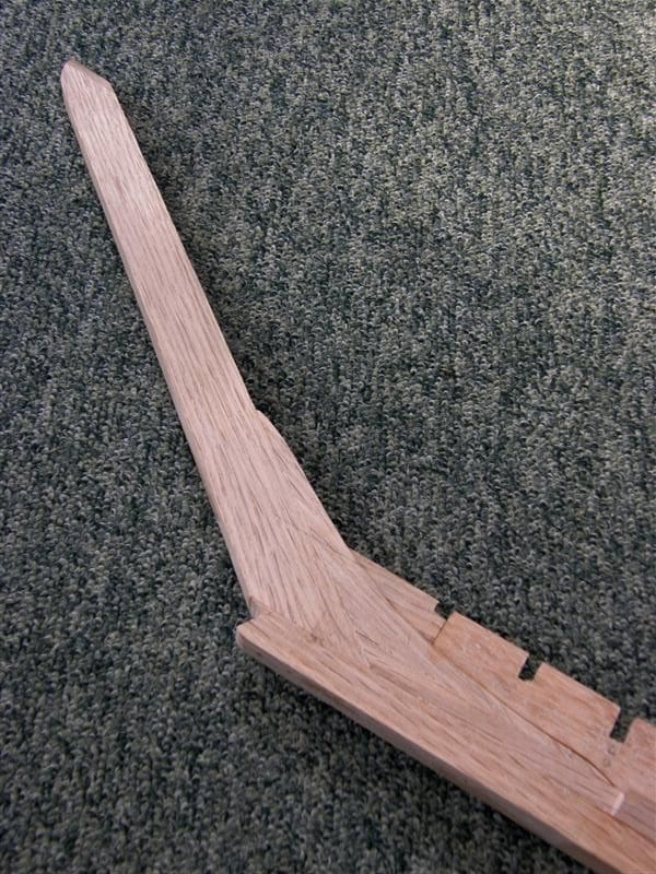
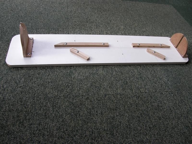
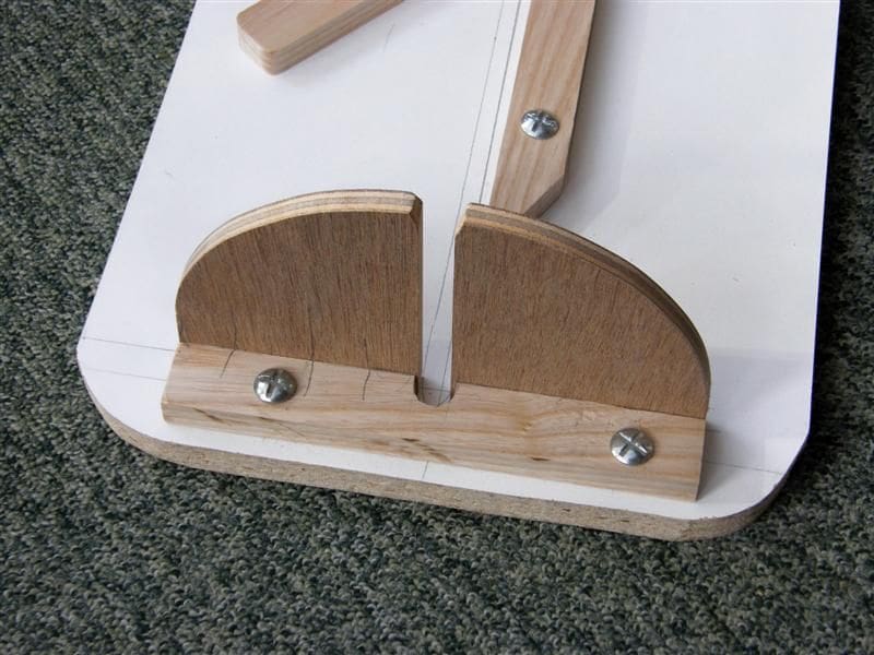
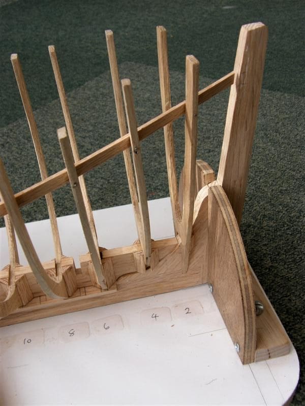
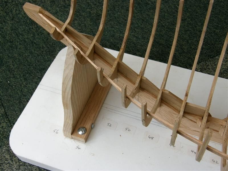
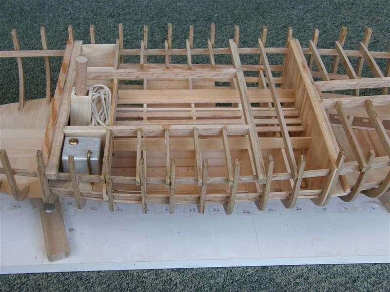
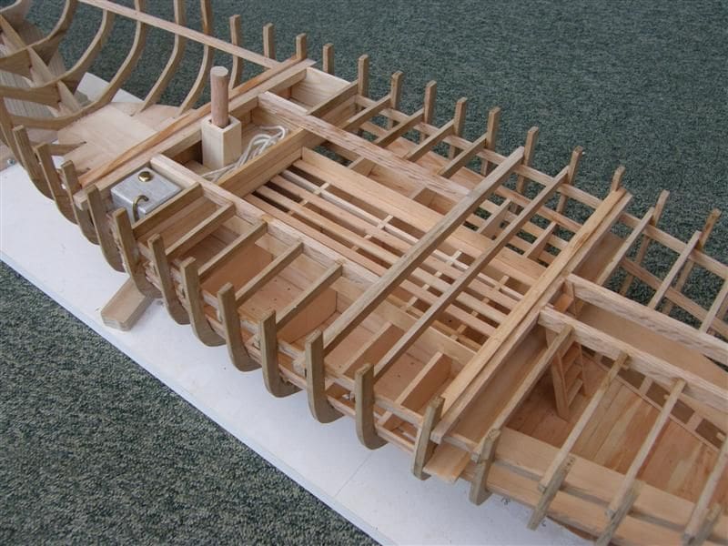
At this stage, I needed a support for the boat and made the board as shown in the pictures. It has supports at each end for bow and sternposts and two simple cams, so that by moving them to one side, the assembly can be immediately lifted out. A 25 x 12mm hardwood strip is fixed in alignment and the keel rests against this. The baseboard is a piece of melamine-faced chipboard 1020 x 250mm, and the fittings are of ash, fixed with M6 x 20mm bolts. Drill the holes in the baseboard for these with a 5mm drill and use a 6mm drill for the ash pieces. The bolts will cut their own thread in the baseboard as you screw them in.
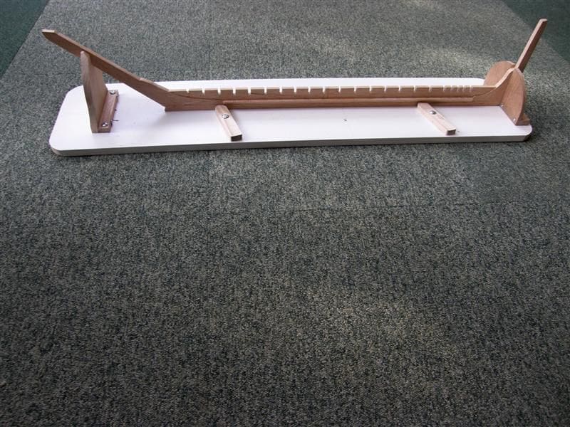
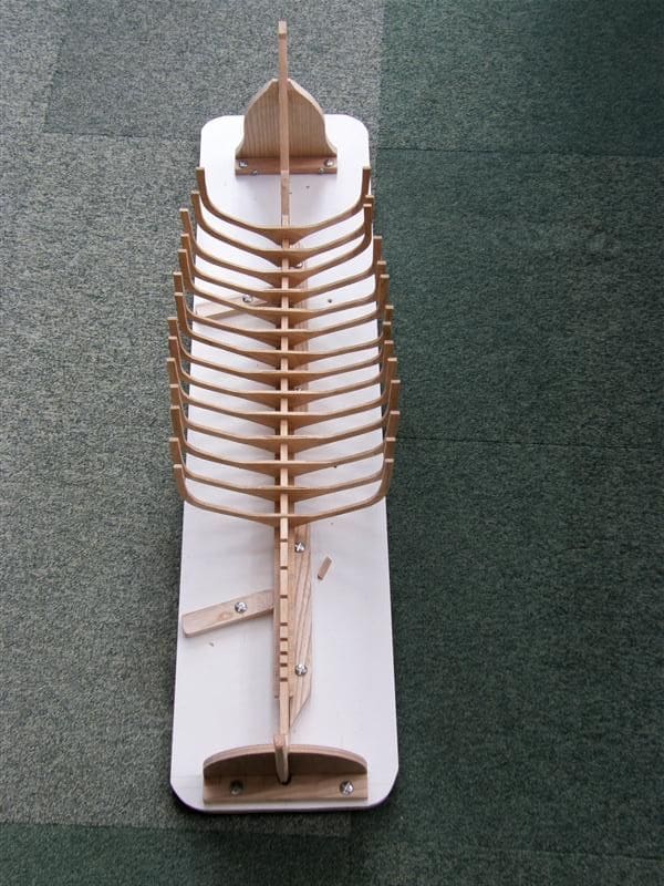
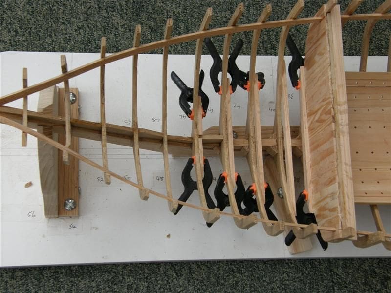
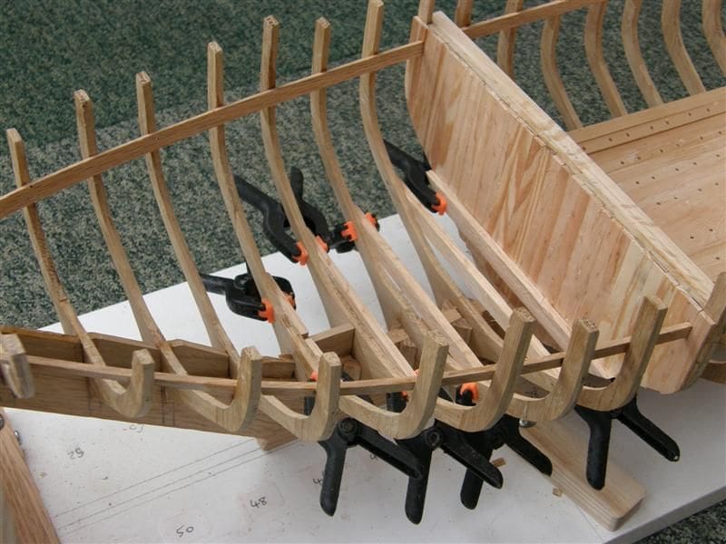
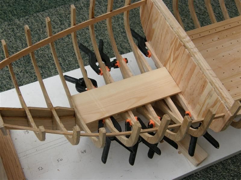
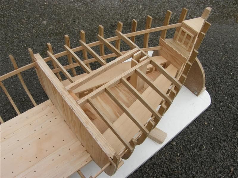
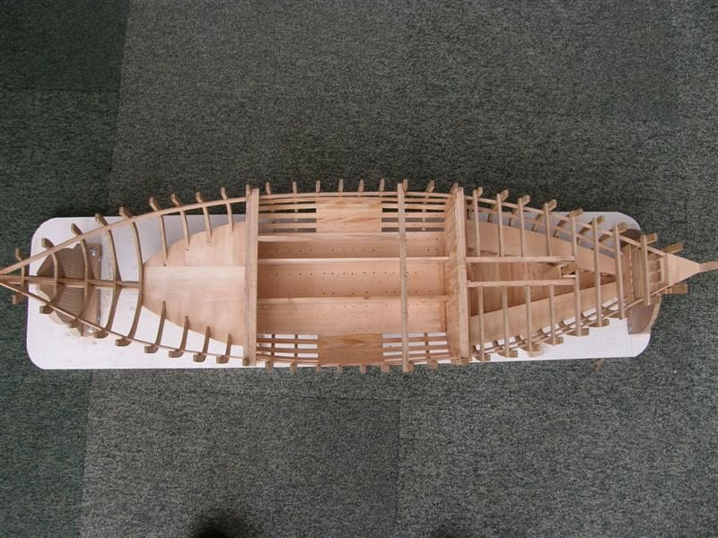
Setting the frames
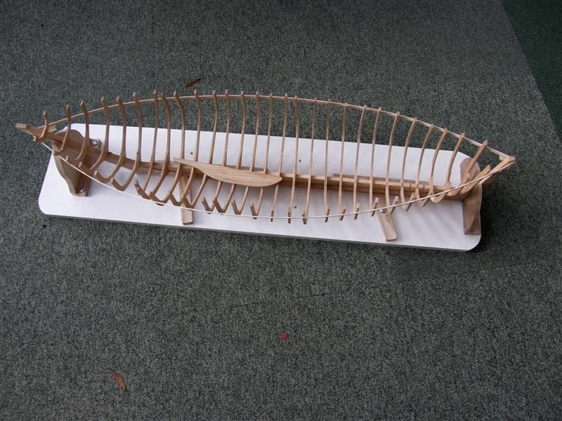
The full sized boat had long bolts to fix each frame, running vertically through keel, keelson and frame floor. Of course, the planking, wales and deck beams all added much strength, but I didn’t fancy making or obtaining 2mm bolts up to 70mm long. Once again I compromised, with a strip of oak 8 x 25mm, the same as for the keelson, but fixed with the 25mm dimension vertical. This was faired between end posts and glued to the keelson after I had marked from the plan the exact location of the frames I was using and had cut 4mm x12.5mm slots with the scroll saw. Each frame was given a matching slot so the frames could all be slotted into place. Careful cutting ensured that all frames were upright and at 90 degrees to the keel. Before fixing permanently, each frame had to have its edges bevelled on inner and outer faces so that the wales (and planking if used) would sit well. The centre frames needed no bevel. Forward of this, frames are bevelled on the forward edge and towards the stern the reverse applies. The actual shaping was done gently with a flap wheel on a flexible shaft. The amount of bevel was checked on a dry re-assembly using a strip of timber 6mm x 1mm fore and aft. I did not need to make a notched jig plate, but as a safety measure, I cut some quadrants of oak and glued 25mm lengths of it between the frame bases and keelson. Having ensured that the frame tops were equal in height, port and starboard, they were glued into place. I left the trimming of the tops of the frames until almost the end of construction.
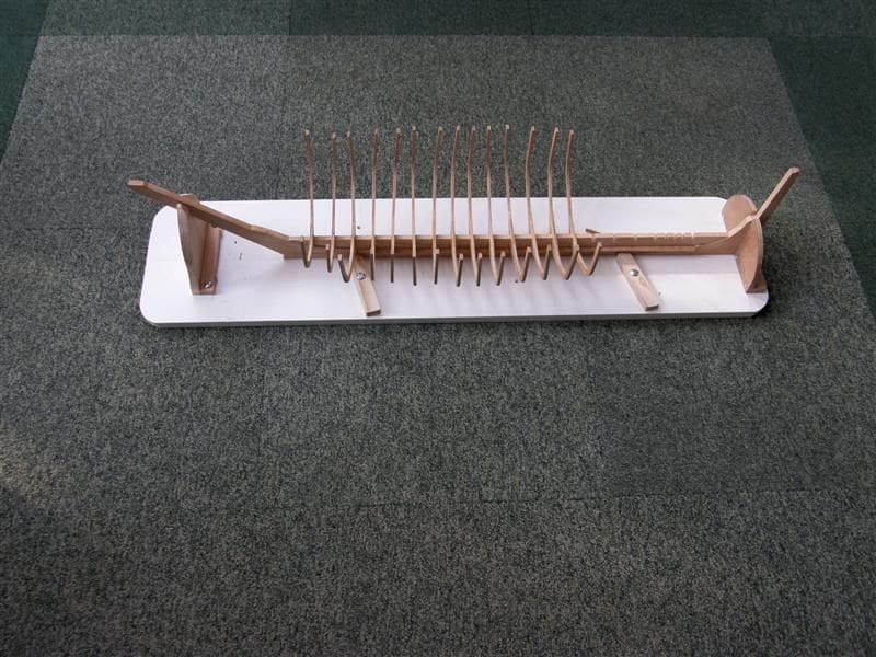
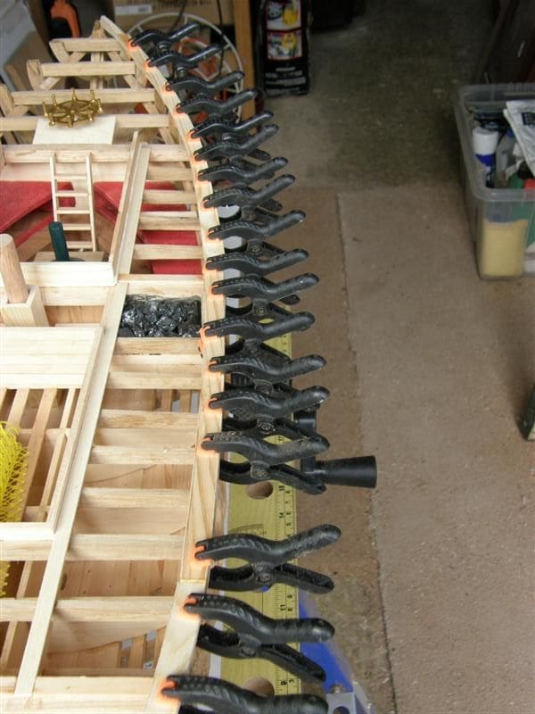
Beam shelves
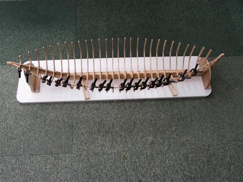
These are strips of oak cut to 7mm x 2mm, running from bow to stern inside the frames. Each has to curve in two planes, horizontal and vertical, but fortunately the wood was so flexible that I was able to do this. It resisted, but I drilled through strip and frame with a small bit and held the strip in position with veneer pins through the holes, whilst the glue (in this case five minute epoxy) set. This was quick and avoided the need to steam the oak strip to a curve.
First bulkhead
The original boat was fitted out with pine, so I did the same. For the flooring, the panel of an old door was ideal. Ripped to 3mm planks and thicknessed to 2mm, each plank yielded two 2mm x 7mm strips 400mm long. I checked the retail price of my first batch and found that one and a half hour’s work produced £45 worth of strip. So, including the oak frame planks, my Proxxon thicknesser had already earned its purchase price.
I cut a master deck beam in oak as a template for all the others. It was long enough to fit amidships, and I shaped on my disc sander a top curve; 10mm deep at the centre down to 7mm at each end. I marked the top to avoid error in the future and the centre for alignment. I then made three more from this template for the boat’s main dividers.
With the first beam glued aft of Frame 20, I added pine cladding strips vertically from its aft side, starting at the centre, and strengthened with a horizontal 7mm strip on the forward face. This strip also acted as a shelf bearer at a later stage.
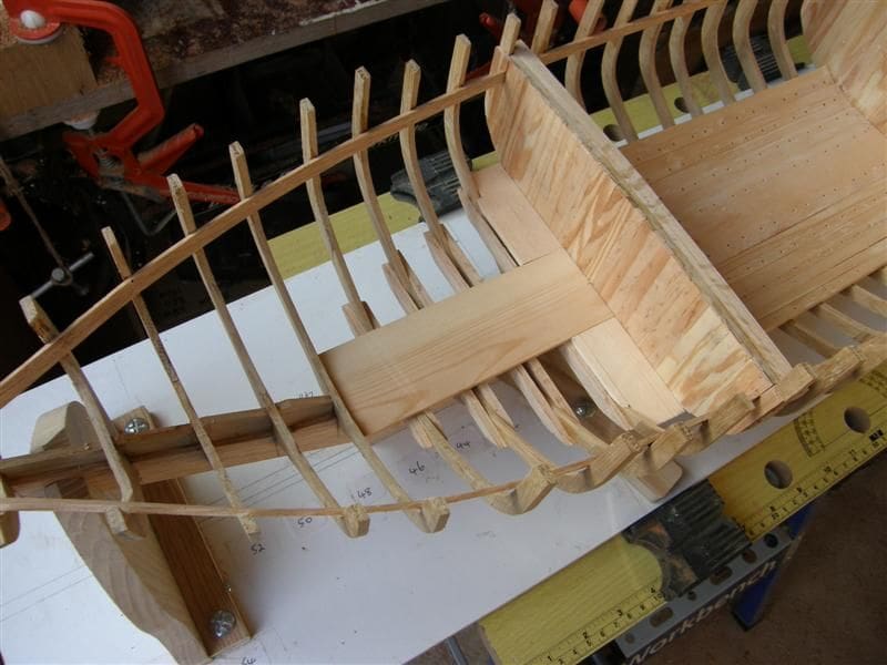
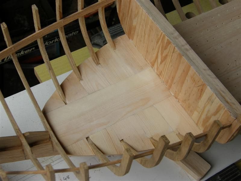
Forecastle floor
To make a firm base for the flooring, I first glued a 35mm x 4mm plank fore and aft along the keelson, between Frames 4 and 20. I used a strip of wood, laid on it athwartships to ensure that it was horizontal whilst the glue dried. Then in the same direction as this test plank, I laid strip flooring to the outer edges of the frames.

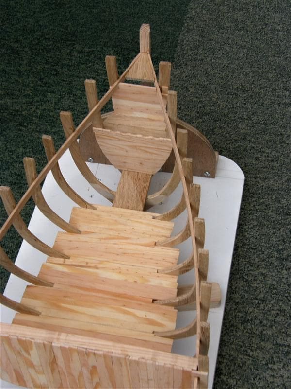
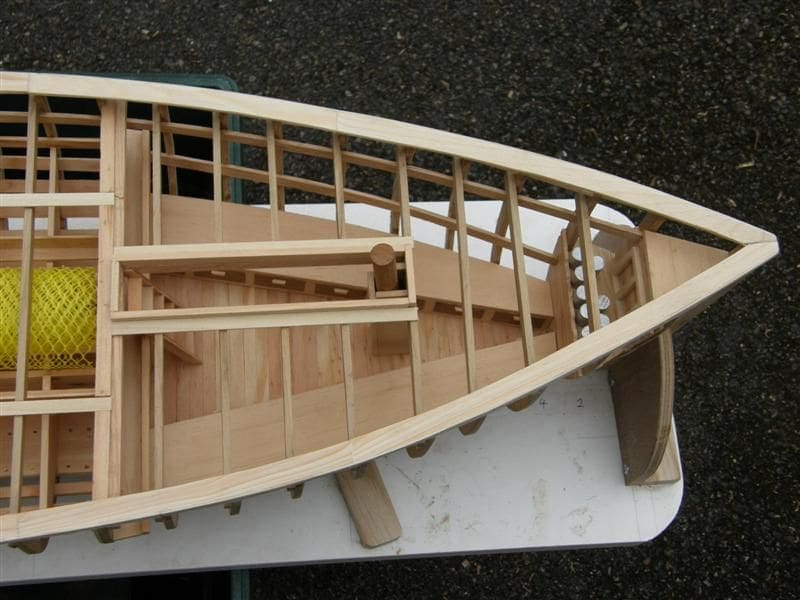
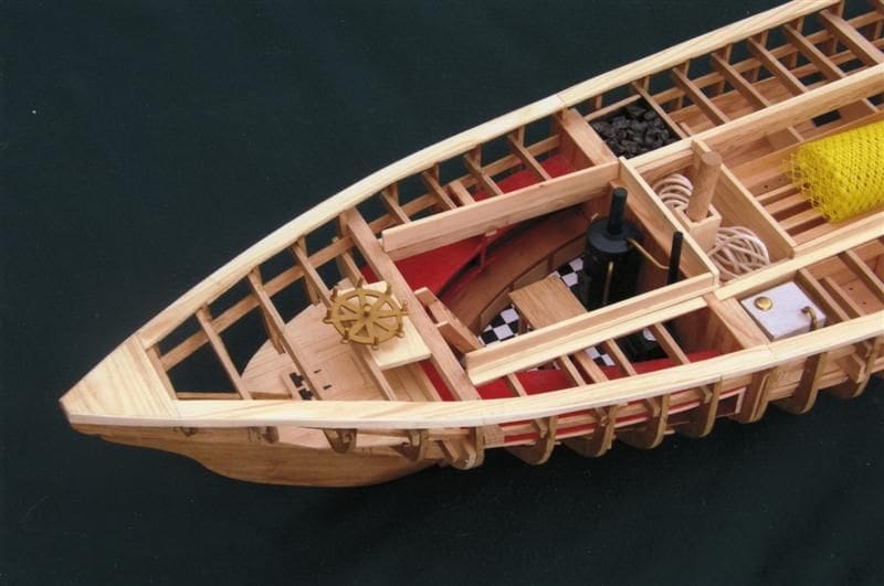
Fitting out the forecastle
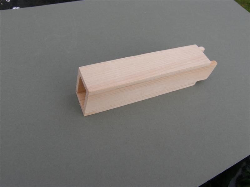
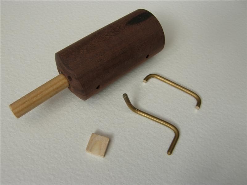
This is the simplest of the three main compartments. There are only curved bench seats with cupboards beneath them, a shelf and cupboard right forward, and a ladder to the deck. The tops of the seating, for which I used 3mm planking, had to be 25mm above the floor, so I placed a 22mm thick curved piece of scrap timber in place on the portside floor and cut a thin card template (by trial and error) to fit between Frames 4 and 20. The inner edge was straight, but the outer edge curved to match the frames. With the template I then cut the pine piece and added a 3mm x 22mm strip under its straight edge decorated with mahogany veneer oblongs to represent cupboard doors and scrap pine for the handles. I did the same for the starboard side. The ladder or companionway, is a simple construction of pine strip 6mm x 2mm and I fixed a shelf behind it. The mast box was made of 3mm pine strip with the top and bottom ends bevelled to give a sternward rake and glued to the floor. I turned the stub mast to produce a 140mm long 12mm rod and just pushed it into its box.
Second bulkhead
This divides the crew’s quarters from the fishpen at Frame 38, and is similar in construction to the first one: Vertical planking over a 10mm x 10mm oak beam.
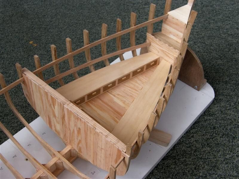
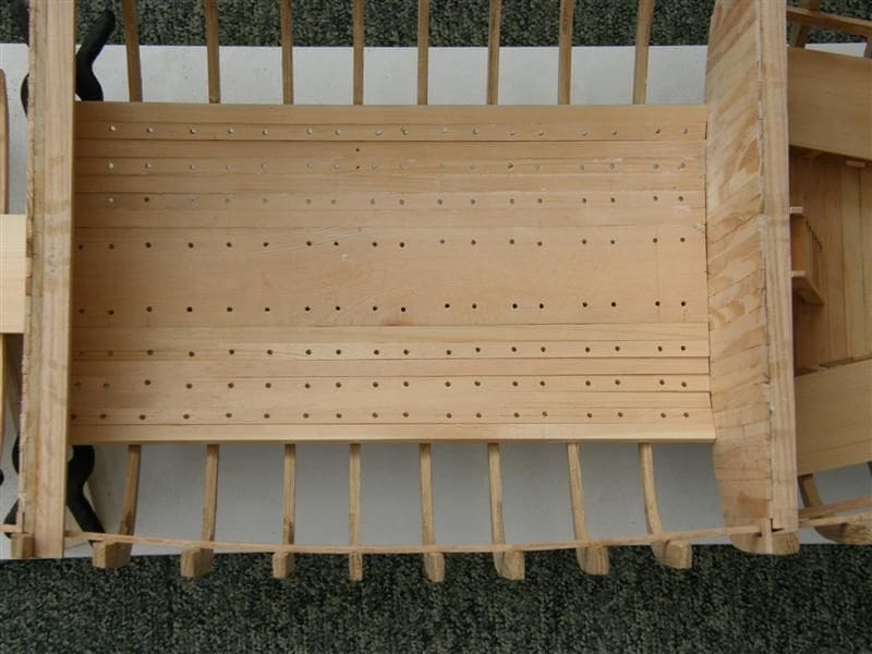
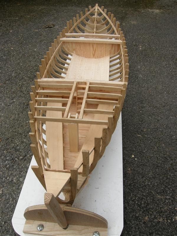
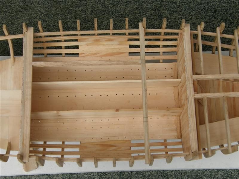
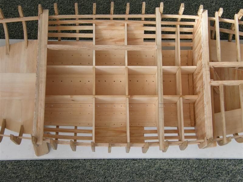
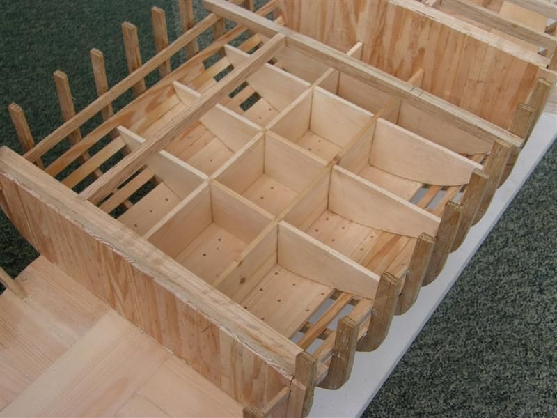
Fishpen
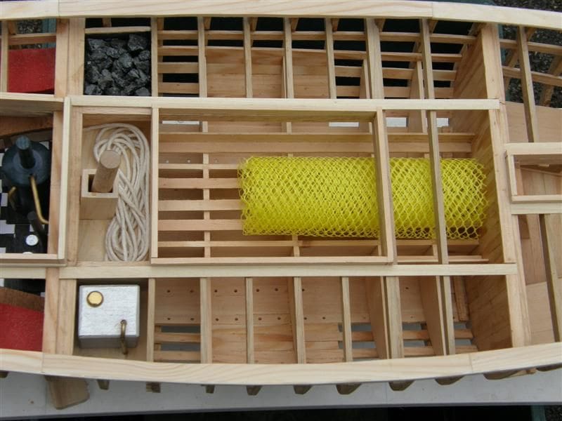
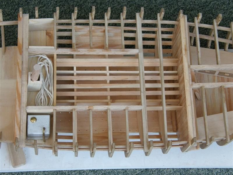
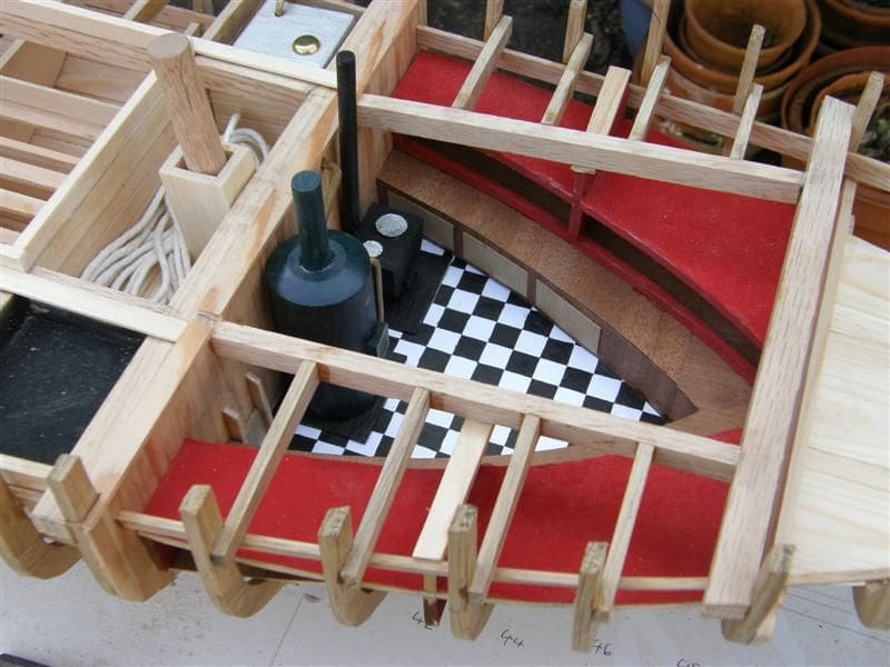
This midships enclosure has two longitudinal and four transverse dividers, which are removable in the full size vessel depending on the catch, but I have made them permanent in this model. First, the bottom has to be planked, which was with 6mm x 2mm pine strips, six each side of centre and alternate planks drilled for drainage. Outboard of these I planked alternately, short and long. Short between Frames 26 and 32, long between bulkheads. This maintains the skeleton structure and the visibility of the interior plus it is a lot easier as you don’t have to taper planks. The central dividers I made 45mm high and the transverse ones matched this at their junctions. On top of these, I glued fore-and-aft stringers of 2mm x 6mm pine (again removable in the real vessel) to carry the nets. The netting in the photo once covered a box of mushrooms at our local market.
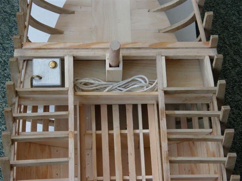
A transverse shelf was fitted between Frames 34 and 38 to form a floor to three compartments surrounding the mast box. These were for a coal bunker, rope stowage and a freshwater tank. These were completed after the deck beams had been installed. The mast box is similar to the forecastle one, but with a forward rake.
Third bulkhead
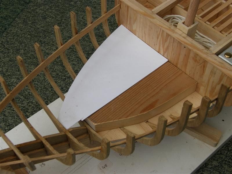
This is at Frame 48 and covers the rear of the crew’s quarters. It can be cut from a single plank 3 x 48mm with its ends shaped to match the curve of the frame, but it wasn’t yet glued in place as space was required to insert the benches and bunks.
Fitting out the crew’s quarters
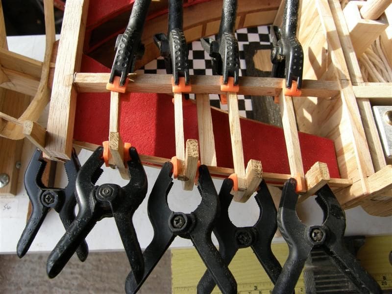
A horizontal bar is fixed at the rear of the third bulkhead, with its top edge 25mm above the keelson. Parallel beams fore and aft of Frames 50/56 were added behind it, ensuring that the tops were all in line. These are the floor bearers and mine were of 10mm x 4mm oak. A central plank was added longitudinally, 45mm wide and then planks added either side out to the frame curves. You will need to cut slots at the outer ends to enclose the frames. These were glued in place, edge to edge.
There is a curved bench either side of the cabin. The front edge is for seating, the rear for bunk spaces with another shelf above for bunks or cupboards, as you prefer. In the same fashion as for the forecastle seating, I used a scrap curved piece of timber on the port side, 18mm thick, as a spacer and cut a card template to sit on it. I used this template to cut a 2mm ply piece, and its front curve to cut from 18mm thick timber a matching front support 3mm wide which I glued under the ply seat. The surfaces of this assembly were then veneered with mahogany and I added oblongs of ash veneer to simulate cupboard drawers. With the same for the other side, these were all glued into place. Upper bench shelves were shaped in the same way and glued in with central spacers 18mm high. I added red suede to the bunks to represent mattresses.
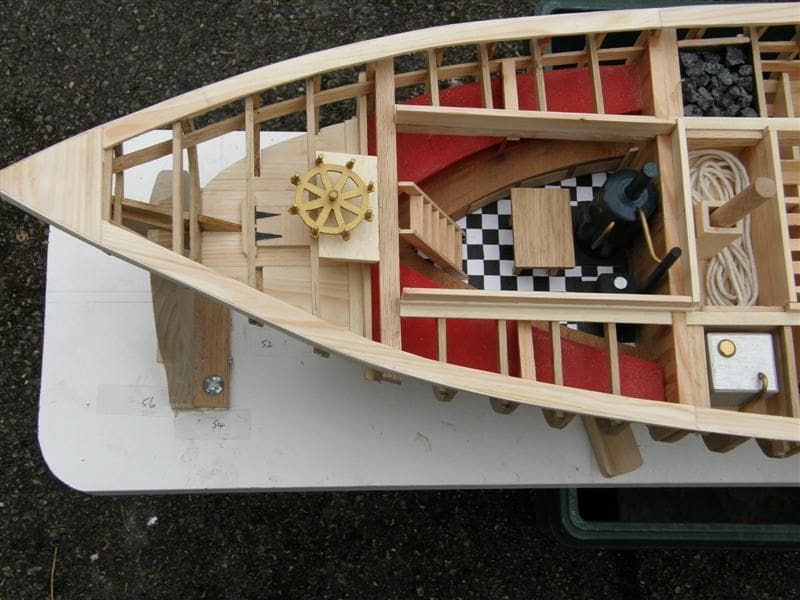
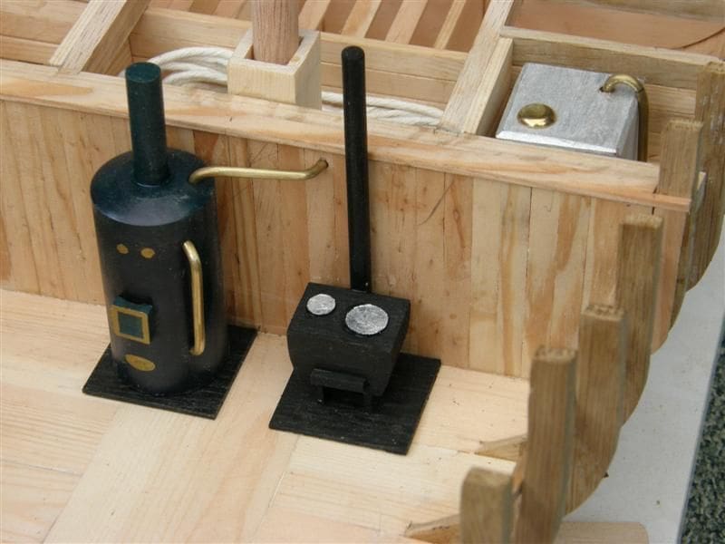
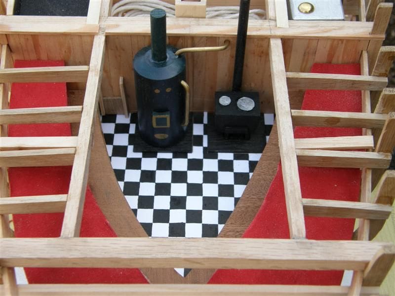
During the foregoing process, the third bulkhead was only clamped in position but could now be glued in position. A paper template for the visible floor area was prepared. From this was drawn and painted in black acrylic on white card, a 10mm chequer pattern, cut to the size of the template and glued to the floor with PVA. The coal bunker hatch, between bench and boiler is simply two strips and a small square of wood, glued to the bulkhead. The boiler was turned to a 30mm x 65mm diameter cylinder with a central top hole of 8mm to take a short length of dowel. The piping is bent 3mm brass rod, fixed into drilled holes with epoxy after the whole assembly had been painted dark green with gold dots to represent dials. The stove is a small shaped block with two card discs for hotplates. Stove and boiler are glued to small square black painted squares of 1mm wood to represent heatproof cast iron base plates.
Deck beams and carlings
The carlings are the fore-and-aft beams which define the hatch sides. Using the master beam pattern made for the bulkhead beams, I cut the blanks for the remaining standard beams, using 10mm x 4mm oak, marking and shaping the top camber. This curve takes only moments on the disc sander. It is useful then to mark the top curved surface, as the camber is so slight and mark the centre too. The first beam to install is that at Frame 10. With the beam centralised, mark and cut off the excess from the ends, and glue on to the rear face of that frame. I used epoxy glue for this. Next, install Beam 28 which should be of 10mm x 10mm oak. These two beams carry the carlings for the forecastle hatch, which can now be fitted between them, 100mm apart. There is of course no camber with these two. All the remaining deck beams were then installed, gluing aft of their respective frame tops. You may find it easier to cut the stub beams (outboard of carlings) one at a time from plain oak strip, rather than cut the ends off full-length ones. Strip softwood was used around all the hatches to create coamings.
Other small details
The freshwater tank on the starboard side of the main mast box is a 35mm cube of hardwood with all edges bevelled and painted silver. The overflow pipe is 3mm brass rod and the inlet cap an upholstery nail (pre-drilled). The central rope locker simply has a hank of white cotton string within. The coal bunker is a slight cheat in that I filled most of it except the top 10mm with block balsa. The rest is actual coal, carefully broken up with a small hammer, and selected pieces set in with epoxy. The steering wheel was cut from 2mm clear PVC sheet because it won’t warp like thin ply. The PVC was first covered with a self-adhesive paper label on which the pattern was drawn copied from the plan sheet. The upright handles on the wheel are ends of cocktail sticks cut to 14mm, epoxy glued into 2mm holes with the underneath excess points sanded off and all painted with acrylic paint of a brass colour.
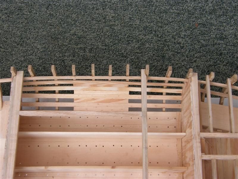
Bulwark rails
The frame tops were levelled at 15mm, marked with pencil and 15mm scrap block. The excess was taken off with an X-Acto razor saw. It helps to hold the top in a pair of pliers when cutting. I filled between the frame tops with 10mm x 2mm pine strips, finishing the top surface with a 50mm sanding disc in a drill, and I smoothed the edge curve with a small orbital sander (80 grit Velcro pad). This created the base for the rail. The 2mm pine planks for this would not cope with double curvature, so each rail was made in four parts, with patterns made from thin card templates. The rails were finished with 6mm x 1mm lime strip glued on the outer curve.
After adding the one-piece oak rudder to the sternpost, I considered the boat to be finished.
Conclusion
No doubt you will modify my methods and add more detail if you build this or a similar model. I hope you do, because whatever you build, it’s your model. I enjoyed this project and was able to build the Zulu relatively cheaply by cutting and preparing quality wood with the tools that I have listed. The personal satisfaction that can be gained from such a project is most rewarding and satisfying. Brown, Son and Ferguson advertise regularly in this magazine and Harold Underhill’s book is a most useful reference and advice source.
Pictures below show the completed model