Vosper Perkasa P150
DAVE ABBOTT reviews the Nautical Marine Models radio control model kit
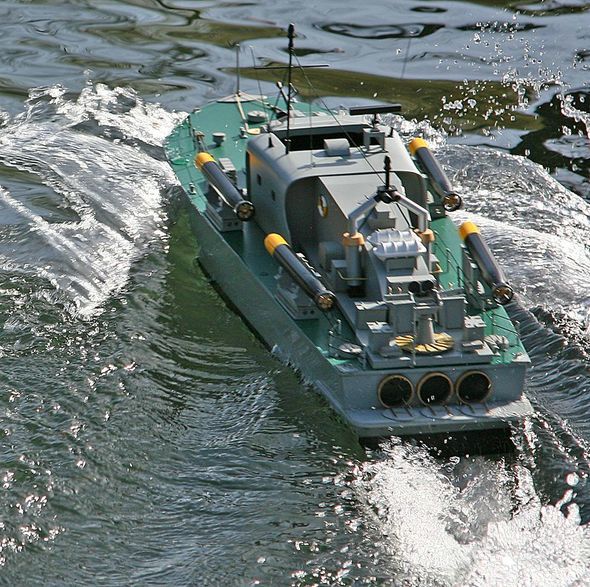
Under full power Perkasa makes fine sight
Enjoy more Model Boats Magazine reading.
Click here to subscribe & save.
Kit contents
Other included materials include balsa wood, hardwood strip, plywood sheet and styrene sheet of different sizes and thicknesses. The running gear can be seen in Photo 2 and this shows the exposed propshafts, P frames and the rudder assemblies in brass and white metal. All of this is of first class quality. The only extras required are r/c equipment, motors, couplings, propellers, batteries, glue and paints.
Getting started
The next and most important task was to make a stand for the model which I regard as essential to provide a stable platform on which to build it. The profiles for the stand are shown in the building guide along with the dimensions. I built the stand from 12mm MDF board which is strong and cheap. Don’t forget to varnish the MDF at least once, as this type of material does not take kindly to getting wet. The finished stand can be seen in Photo 3 and the stand and prepared hull are in Photo 4.
Fitting out the hull
The propeller shafts and rudder assemblies need to be installed next and the building guide gives measurements of the holes that need to be cut in the bottom of the hull. The motors, couplings, propellers and tiller arms are not included in the kit (as is normal with most r/c kits), so it is a good idea to have these to hand at this stage. This will enable the running gear to be set up and aligned easily and correctly rather than later in the build. Suggestions as to suitable motors etc. are included in the kit instructions.
The deck supports were also fitted at this stage. These are installed in a frame pattern, similar to a model aircraft frame using the supplied balsa and hardwood strips. Glue used was once again two part epoxy. Don’t forget to rub down the contact areas on the inside of the hull before gluing, Photo 9.
The deck and a minor modification
This is cut to shape and is intended to be a one piece item with cut-outs for access to the r/c equipment and batteries as shown in Photo 10. In this form there is adequate access through the openings as can be seen, but I decided to make the whole after deck piece removable for even more access to the r/c equipment, motors and rudder linkages. I hope the manufacturer will forgive me for doing this, but it does make access easier and providing that the removable section is well sealed and secured, there should be no problem with water ingress. This removable section is shown in Photo 11. I stress this was a personal choice – it made life easier for me, but there is nothing wrong with the recommended constructional method.
Superstructure
With the hull, deck and superstructure complete, the horizontal transom plate was fitted to the stern and Photo 14 shows everything made so far temporarily fitted in place.
Radio control installation
The bulk of the r/c gear is installed under the after part of the superstructure and Photo 15 is an overhead view of this. As you can see, there is adequate access via the opening underneath the superstructure, but you can also see where I cut the deck to make the whole section removable. It really is just a matter of personal choice. As on many of my other projects I have found that simple is best for electronics. I used two channel r/c, the left hand vertical axis stick for forward and reverse and the right hand horizontal stick for steering. Batteries used were two 3300mAh 7.2v car buggy type of packs for the main motors power, and the speed controller was a Ripmax P-Xtra Seasprint 40amp forward and reverse with provision for water cooling, but this was not necessary on this occasion. A battery eliminator circuit was not used, so a normal four cell receiver battery pack was also installed. The transmitter and receiver were a Zebra 40MHz two-channel set, that is more than adequate for the task.
Fittings
Assembly and positioning of all the fittings is very straightforward with nothing too taxing. As with the rest of the kit, the resin, etched and white metal parts are all first class, fit together well and require little effort to prepare for painting. Most of them were temporarily fitted on the model as can be seen in Photo 20 to get an idea of what the finished model was going to look like. They were then removed and painted separately.
Painting
Photo 23 is of the foredeck and Photo 24 is a close-up of the 40mm Bofors gun. As you can see, I have included a bit of light weathering to emphasise and highlight the features. Finally, Photo 25 is a picture of the transom with the massive exhausts from the gas turbines. When completely painted and I was satisfied with the overall colour coat finish, two coats of Humbrol clear satin varnish were applied to everything.
Access
I have already mentioned my personal modification to the rear deck and Photos 26 and 27 highlight the difference in access by having a completely removable section, but it is a matter of choice.
On the water
Using the recommended motors, batteries and propellers proved just right and as can be seen from the on the water pictures the model did what it said in the instructions. I have seen many models of the Perkasa before, but not planing just right and this combination of motors and batteries seems to be just perfect as can be seen in these pictures.
Conclusion
Kit details
Vosper Perkasa P150 kit
Price: £200
Available from:
Nautical Marine Models
17 Liverpool Road North
Burscough
Lancashire
Tel: 01704 894006
Monday to Saturday, 9am to 5pm.

