During 1942, less than 11 months into WWII, the United States Navy had lost four front line carriers due to enemy engagements. A further two aircraft carriers were damaged, but were repaired at Pearl Harbor and returned to service. These early engagements and losses emphasized that carriers would be the backbone of the war in the Pacific. While American industry would build carriers and their airplanes, it was up to the US Navy to train the pilots and crews that would be necessary to make the ships and planes an effective fighting force. The Navy was hard pressed to come up with a solution to solve the training dilemma.
Training the pilots and crews for aircraft carrier operation on either the Atlantic or the Pacific Ocean would have exposed the training ships to the danger of submarine attack, while requiring the escort of fighting ships that were needed elsewhere. It would also have involved arming and armouring the ships used for training. It was then that Commander C.F. Whitehead came up with an idea that would solve these problems. He suggested doing the training on the protected waters of the Great Lakes. Once the U.S. Navy had agreed with his choice of Lake Michigan as the location for the carrier pilot qualification training program, the next priority was to secure an aircraft carrier.
Using a fleet carrier was out of the question for two reasons; by the time the decision was made to adopt the training program, the United States was already at war and needed all its commissioned carriers at sea. Furthermore, no existing carrier was narrow enough to use the Welland Canal to sail from the Atlantic Ocean to the Great Lakes. This width restriction barred the conversion and use of other ocean going ships, with otherwise appropriate specifications, as well.
This left the Navy with two choices: build a new aircraft carrier from scratch or convert an existing ship to an aircraft carrier. Building a new aircraft carrier would have taken too long and would have tied up shipbuilding capacity needed for other war-related construction. Thus, conversion of a ship already sailing on the Great Lakes was determined to be the best way to go. The Auxiliary Vessels Board recommended that the training carrier should have a flight deck of at least 500 feet long and be capable of a speed of 18 knots.
Enjoy more Model Boats Magazine reading in the monthly magazine.
Click here to subscribe & save.
In Commander Whitehead’s survey of available ships, the choice for conversion was narrowed down to two vessels: the SS City of Midland, a car ferry owned by the Pere Marquette Railroad Co., and the SS Seeandbee, a Great Lakes excursion cruiser. Because the car ferry was shorter, slower, and already making a contribution to the war effort, which the Seeandbee, as a recreational ship was not, the Seeandbee became the vessel of choice.
The SS Seeandbee had been built in 1913 by the Detroit Shipbuilding Company to cruise Lakes Erie, Huron, and Michigan. At 500 feet in length, she was long enough to accommodate a useable flight deck; she was fast enough ( 17.5 knots ),with a modest headwind, for adequate take-off and landing speeds and, being a side-wheeler, she had great resistance to rolling. Commander Whitehead saw that there were many features of the SS Seandbee that were appropriate for the conversion so he had sent two officers, one from the Bureau of Ships and one from Fleet Training Division, to inspect the vessel. They agreed with Commander Whitehead’s opinion. They were especially impressed by the width over the sponson deck (wheelhouse area), which, at 98 feet, was wider than the deck of the USS Essex! The ship’s main disadvantages were that it was coal-fired at a time when the rest of the Navy was oil-fired, and it had a tall superstructure filled with very ornate and expensive fittings which would have to be removed and scrapped. Commander Whitehead was not put off by all this grandeur!
The C&B Transit Company, current owners of the SS Seandbee, reflecting upon frozen prices, lack of replacement parts, the shortage of manpower for maintenance, and an almost $800,000 dollar offer, agreed to sell the Seandbee to the U.S. Navy on March 10, 1942. On April 14,1942, the conversion of the SS Seandbee was begun in Cleveland, Ohio, with the removal of the five magnificent (mostly wood) upper decks along with their contents of settees, davenports, bed springs, carpet, pillows, lifejackets, basins, and bar stools, along with thousands of other items. The hull was then moved to the American Shipbuilding Company’s yard at Buffalo, N.Y. The rest of the conversion involved construction of the massive flight deck with a surrounding catwalk, an ‘Island’ structure, and many other areas to make things ‘feel’ like a fleet carrier.
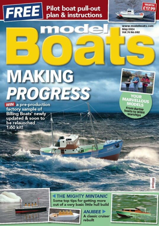
The flight deck was a mere 26 feet above the waterline, less then half the height of a conventional carrier, but it was 98 feet wide to cover the paddlewheels, and 558 feet in length. There was no catapult or hanger deck, but there was a nine wire arrestor system and three barrier arm assemblies to keep planes from running off the deck into the chilly waters of Lake Michigan. The main deck area included officers quarters aft, wardroom, and crew quarters forward, as well as a motion picture equipped instruction room, a ship’s store, laundry, tailor shop, barber shop, dining rooms and a crew rec. room. There was also a state of the art Galley, as well as radar rooms and air plot facilities. The small ‘island’ constructed on the starboard side just forward of the wheelhouse was to provide ‘realistic’ appearance. This structure housed the four funnels and limited command facilities, the object being to make the training as real as possible. The ship carried no armament or armour but she did carry various types of early air-search radar. When the conversion was completed, the new ship had the following specifications:
Displacement: 6,381 tons.
Length of hull: 500 feet.
Beam: 99 feet.
Draft: 15 feet, 5 inches.
Length of flight deck: 558 feet, 6 inches.
Propulsion: Six single-end and three double-ended coal-fired boilers driving a reciprocating three cylinder steam engine which in turn drove two feathering paddlewheels, each 32 feet in diameter, with 11 feathering blades each, and weighing in at over 100 tons each.
Maximum Speed: 17.5 knots.
Ship’s complement: 22 Officers and 300 enlisted men.
Techniques and procedures learned from the conversion of the SS Seandbee to the Wolverine were employed in another conversion to the SS Greater Buffalo, a ship similar to the Seandbee, which would become the USS Sable. The most dramatic difference between the two ships was that the Wolverine was fitted with an oak flight deck in common with the fleet carriers of the time. The Sable had a flight deck made up of two designs of steel flight decking topped with eight types of non-skid coatings applied in a chequerboard fashion. She was also heavier and slightly faster than the Wolverine. Both ships would be based in Chicago, Illinois near NAS Glenview.
Throughout the duration of the Second World War, the USS Wolverine and her sister ship, the USS Sable, qualified more than 18,000 pilots and as many or more of flight deck crews for aircraft carrier operations. These two ships were the only coal-fired paddlewheel aircraft carriers in the history of the world. Sadly, both were sold for scrap by 1948, thus an obscure page in U.S. Naval history was closed. The USS Wolverine and the USS Sable played an invaluable role in the outcome of the Second World War, which would lead to the eventual defeat of the Axis powers. Commander Richard F. Whitehead, the man responsible for suggesting this chapter in Naval aircraft history died in 1993 at the age of 99. He was a retired Vice Admiral.
Author’s note: some of the above next used by permission of Arcadia Publishing, from the book, ‘Lake Michigan’s Aircraft Carriers’ by Paul Somers, c2003.
Construction of the replica
I must admit, when I was approached by the Kalamazoo Aviation History Museum to possibly build a replica of the ship, I had no idea that the Wolverine and her sister ship, the Sable, even existed. A paddle-wheeled aircraft carrier? I was dumbfounded. After viewing some of the reference materials the museum had, and then obtaining some plans, I was confident a model could be built but more research would be needed. The Wolverine is such an obscure subject that not much good reference material exists any more. I was fortunate to meet a person on the internet, Mr. Doug Wilde, who is an expert on these two vessels. A lot of the information on the ship came from the National Archives in Washington, D.C., which Mr. Wilde visits quite often. He was kind enough to pass this information on to me so the project was a go!
Hull and main deck
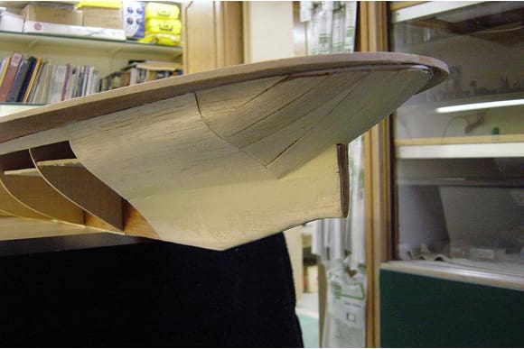
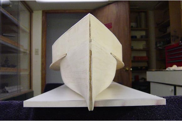
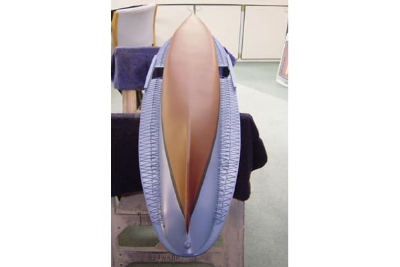
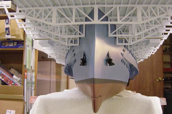
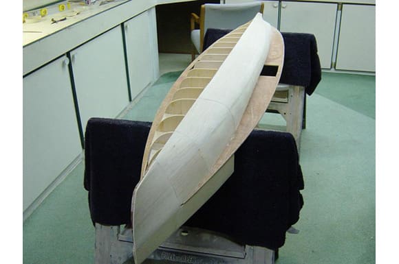
Basic construction started with the fabrication of the main keel from 3/16in plywood. I then added all the bulkheads or stations as they are sometimes called, from 3/32in hard balsa sheet stock. Stiffeners were then added between the bulkheads to add rigidity to the structure, from 3/16in balsa sheet. Once I was satisfied with this basic framework, I decided it was a good time to add the main deck to the hull, which would further stiffen the structure. It is fabricated from 3/16in plywood. I was now ready to cover the hull structure. This was accomplished using 3/32in balsa sheeting on most of the hull, except for the stern, where 3/8in balsa planks were used, due to the compound curvature of the hull. I like to use bigger sections of sheet balsa rather than narrow planks wherever possible. This speeds construction time. To get the balsa sheeting to bend around the tight curvature of the hull, without splitting, I soak the sheets in hot water for a couple of minutes to get them pliable enough to form around the bulkheads. After all sheeting and planking was completed, and I was satisfied with the shape of the hull, I began applying three to four coats of epoxy marine resin, sanding smooth between each coat.
Now that that the hull was sealed and sanded smooth, I began adding coats of lacquer- based automotive primer/surfacer. Product is Dupont 131S grey. This product ‘builds’ fast, and sands easily to take out small imperfections. Many coats are applied, again sanding between each coat. I then started the final shaping of the bow and stern areas, plus all other areas that required attention, with polyester auto-body filler, also known as ‘Bondo’. I will sand, shape and prime all areas until all is smooth and uniform. Then it is on to other details before final paintwork.
It was now time to add further details to the hull before final paintwork. All the portholes along the sides of the hull were drilled out. I then added small rubber ‘O’ rings over these holes. Anchor hawses were added, and then the forward and the aft rudder assemblies were mounted. The rudders were fabricated from thick balsa sheet.
The bracing to support the main deck was the next item on the schedule. There are over 200 of these braces around the underside of the main deck. There are four parts to each brace. The construction of this bracing was first laid out using a template I made using the plans as a reference to get the correct spacing between the braces. Small plot marks were added using a sharp punch where each main part of the brace attaches to the hull. Holes are then drilled into the hull at these plot marks. I then installed all the main parts of the braces using .060in square styrene strips. Next, I went back and drilled holes for the diagonal and vertical pieces of each brace, also 0.060 styrene, and then added them to the main part of the brace. Finally, I came around again and added a small cap from thin strip styrene where all three pieces of the brace come together.
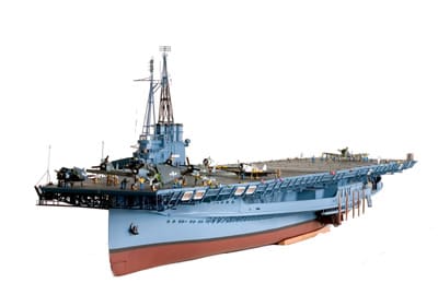
After all this bracing was completed, I applied more primer. After looking everything over to make sure all was good, it was time for paintwork. I first taped off the waterline and painted the lower hull using Testor’s Model Master Enamel, Hull Red. I then taped off and painted the black boot topping. Finally, the rest of the hull was finished in the appropriate colour, 5-S, Sea Blue using Testor’s Marine Acrylic.
Now on to more work on the main deck. To simulate planking on the main deck, I used some 0.040 walnut veneer sheets that had the plank lines laser cut into the veneer. These veneer sheets are then glued to the main deck plywood. I was very happy with the laser cutting. After the veneer is added, I wrapped the entire edge of the main deck with 0.030 styrene strip. The deck is then stained a medium oak colour, with a flat lacquer topcoat.
Paddlewheels – Wheelhouses – Superstructure
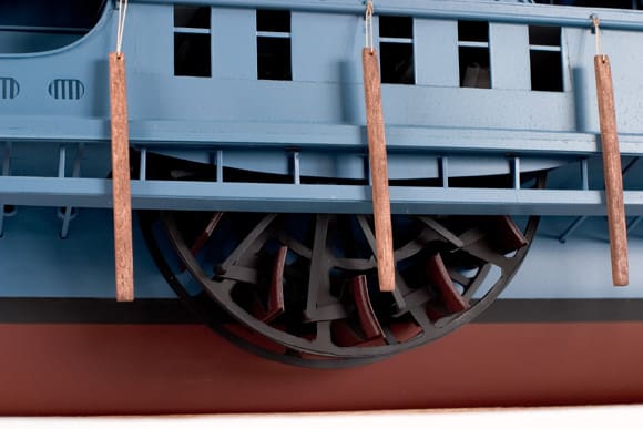
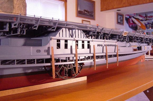
Now that the hull was pretty much completed and the main deck was installed and planked, it was time to move on to one of the more time consuming aspects of the build, the paddlewheel assemblies.
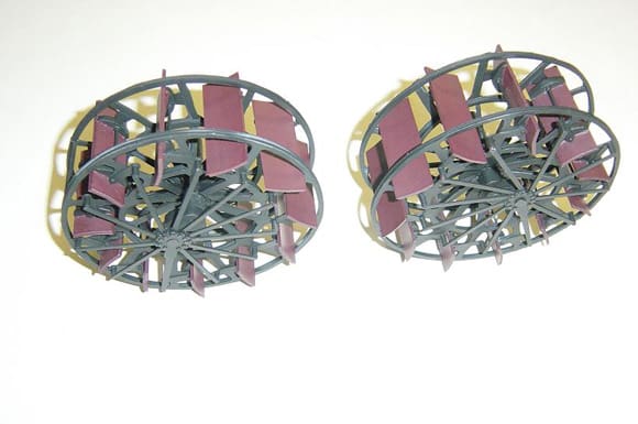
There are over 200 individual pieces to each wheel assembly. It would take up much space to describe every operation involved in the construction of these wheels, so I will try to condense things a bit and outline the sequence of construction. First, I would like to say that I had very good drawings of these wheel assemblies, without which I would not have been able to duplicate them reasonably accurately.
The initial step was to make the rings of the wheel. Think of this as a wheel on a bicycle. You have a centre axle and then spokes going outward towards a ring, which a tyre will mount to. In the case of the paddlewheels, the outer ring has spokes, which will connect to another inner ring before the axle, or in this case the main driveshaft. There are more spokes then connecting to the inner ring to the main shaft. These spokes are angled inward at about 70 degrees and attach to brackets on the driveshaft. There are two rings, an inner and an outer. Basically, two bicycle wheels, side by side with a space between them. To make the actual wheels, I glued side view drawings of the assembly to 0.015 poster board and then cut out the rings and spokes from one piece. The rings are backed up with 1/16in H-column styrene. The spokes are backed up with 0.015 sheet styrene. I also added small shafts to the inside of the flanges that are attached to sprockets between the outer and inner rings. These shafts will hold the paddles.
Once the rings and spokes are finished it was on to the main driveshaft assy. The main driveshaft was fabricated from 3/8in wood dowel. I then plotted the location of the eleven brackets that will attach to the spokes from the inner ring of the wheel. These brackets are then made from 0.030 sheet styrene and fastened in place on the driveshaft. The rings are then installed, attaching the spokes from the inner ring to the driveshaft brackets. I now have an assembly, which resembles an ‘H’ if viewed on end.
Next, the paddles, or ‘buckets’, as they are sometimes referred to, are fabricated from 1/32in balsa sheet. There are two brackets, which are attached to each paddle. I built these using a mould I made and then casting all of them at once from resin. After the resin was cured, holes were then drilled into the brackets to accommodate the short shafts mentioned above. After attaching the balsa sheet paddle to the bracket, I then laminated a 0.010 piece of styrene to the balsa sheet. The styrene adds rigidity to the paddle assemblies, as they have a slight curve to them.
Paddles are then added to the wheels by spreading the rings apart slightly and sandwiching them between the short shafts previously installed. They were not glued, but left movable.
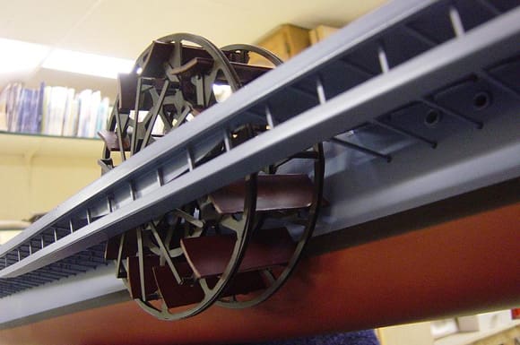
The next step was to add the articulating mechanism. First, an offset arm is fixed to the main driveshaft with a casting on the end of the arm that looks somewhat like a sprocket, where the 11 articulating arms will attach. Then, the offset brackets are added to each paddle on the wheel. Finally, the arms between the sprocket and the offset brackets are installed. The paddlewheels are a complex assembly and required much time and planning to model accurately. The second one went smoother than the first! I would not want to do them again! The completed wheels were then primed and painted flat black. The paddles were then brush painted hull red.
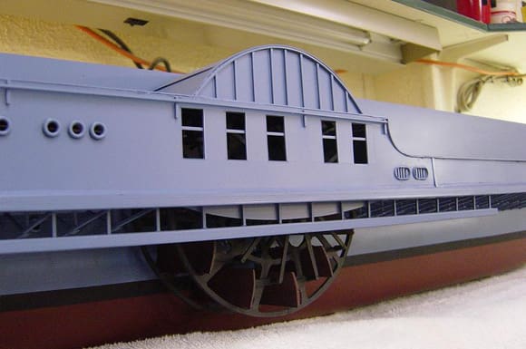
It is ironic that you can only see about 35% of these wheel assemblies after they are installed on the ship, due to the fact that the wheelhouse covers most of them. The completed wheel assemblies are then mounted to their correct position on the main deck.
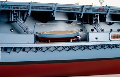
The walls of the main deck superstructure would now be the next item to complete. These walls are fabricated from 0.040 sheet styrene-using patterns I made directly from the plans. After dry fitting the walls to the main deck to be sure all fit well, I constructed a frame onto the main deck, to which the walls would be attached. The frame is made from 3/16in stick balsa. All the details on the walls, such as portholes, hatches, etc., are added before they are mounted to the framework. After mounting the walls, cross bracing was added using balsa sheet stock to add rigidity to the structure.
The wheelhouses were fabricated in much the same way as above.
The addition of the bulwarks was next, again using 0.040-styrene sheet. Details here are added before mounting, also. A ‘cap’ was then added to the bulwarks using styrene strip, again 0.040. After all was completed as far as construction here goes, I masked off areas and then primed and painted everything the appropriate sea blue colour. Finally, all deck hardware was painted and installed using cast metal or resin fittings.
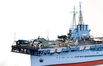
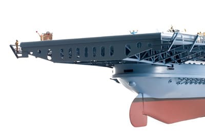
Flight deck
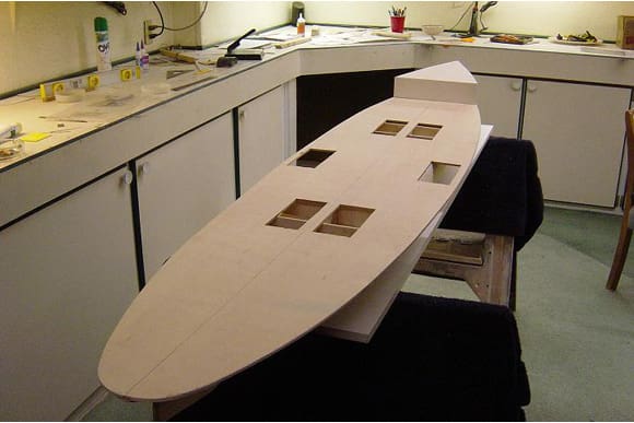
The flight deck is a model in itself. There is a massive amount of framework beneath the deck that supports it. All would have to be fabricated. A time consuming task at best! I started out by cutting out the flight deck from one piece of 3/16in plywood sheet, the same as the main deck. The bottom of the deck was then painted with some white latex paint in order see the layout lines for the support structure. Next, the flight deck was placed on the hull structure to check all centrelines and to trace out the outline of the main deck superstructure walls where the supporting truss assemblies would stop. After I was satisfied that all was straight and on centre, I removed the flight deck add began adding all the plot lines in pencil where the support structure would be mounted.
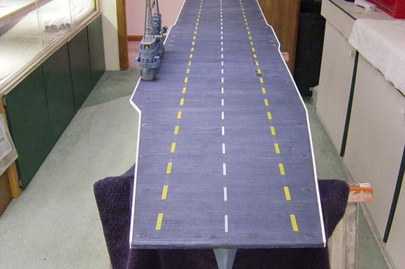
It was now a good time to add the planking to the flight deck. Instead of using individual planks, I decided to use thin veneer here as was done on the main deck. The plank lines are burned into the veneer with a laser, look quite realistic, and save much construction time. Two sheets of veneer would be used, each sized 24 x 48ins, allowing the laser cut plank line to run the same direction as the grain of the veneer. These sheets are then attached to the plywood flight deck using contact adhesive. Excess material is then removed, and the edges are sanded smooth, straight, and uniform. Styrene strip was then added around the entire edge of the flight deck. The veneer decking is then stained the correct dark blue colour (flight deck stain No. 21) which I had mixed up by a local paint store. Once the stain had dried thoroughly, it was then coated with clear, flat lacquer.
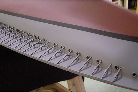
The dashed lines on the flight deck were then masked off and airbrushed white and yellow. Other details are then added such as the arrestor wire stations, barrier arms, flight deck lights and tie-down tracks. These details are all scratch built using styrene product again. More detail will be added here later in the build. It was now on to the support structure.
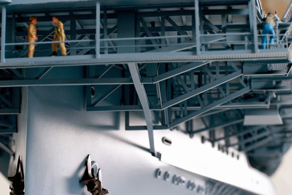
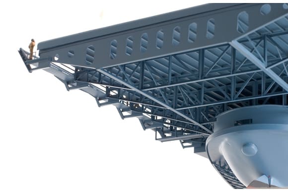
Superstructure
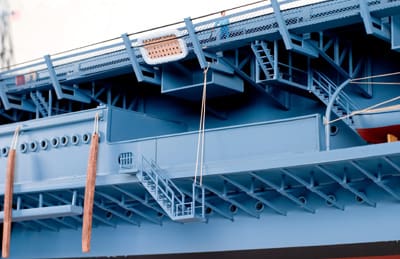
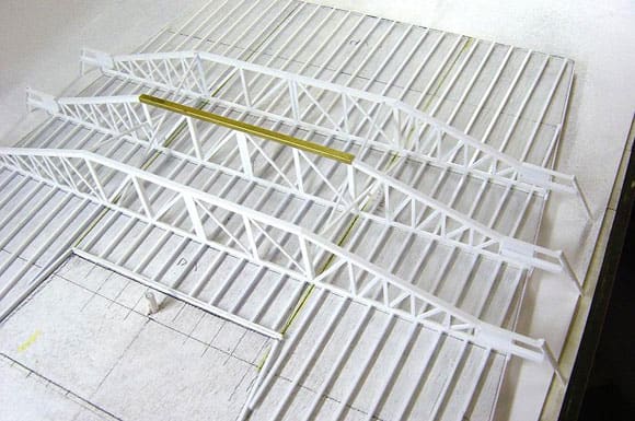
To begin the support structure, all longitudinal I-beams were added first using 1/8in shaped styrene, using the pencil lines I added earlier as a guide. After this was finished, it was time to build all the supporting trusses. There are 84 of these trusses and all are pretty much the same configuration except for their length due to the curvature of the main deck superstructure walls, which the trusses butt against. Therefore, a jig had to be built to speed the construction time. After measuring the length of each truss, they are fabricated and installed one at a time, going the entire length of the flight deck, first starboard side, then portside. The pencil lines previously drawn help to measure the length and align each truss. The trusses were fabricated using styrene product again – angle shape and flat strip to be specific. The first few forward trusses and the last few aft trusses run the entire width of the flight deck, so they were a little different from the rest.
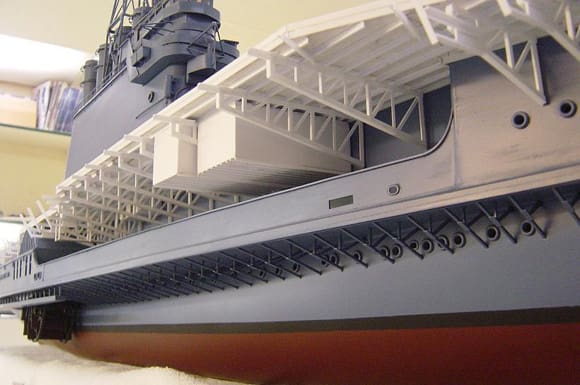
The support structure looks complicated, but it was straightforward once I got into it. Cross bracing was added in places after all the trusses were installed. Further details were then added including shelter pockets, blower intakes and exhausts, suspended catwalks, etc., after which all was painted.
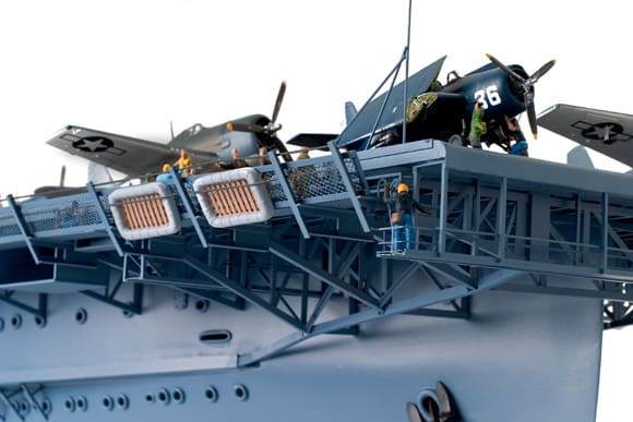
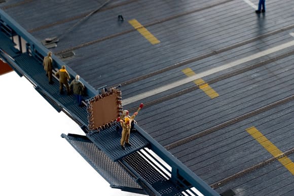
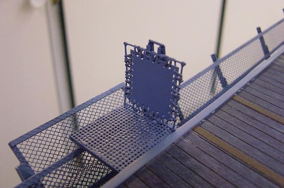
Moving on, now that the support structure was complete, the catwalks around the edge of the flight deck and other details would now be added. The catwalks are made from perforated 0.020 sheet brass, cut into strips then attached. Since the supports for the catwalks are integral with the trusses, this step went rather quickly. Safety netting was then added, using a styrene frame and nylon mesh in sections about 12in long each. The LSO platform was added at this time also. Masking off areas and paintwork were then done. More details will come after the flight deck is installed on the hull assembly.
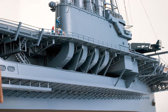
Island / Bridge assembly
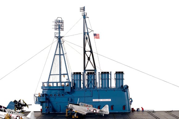
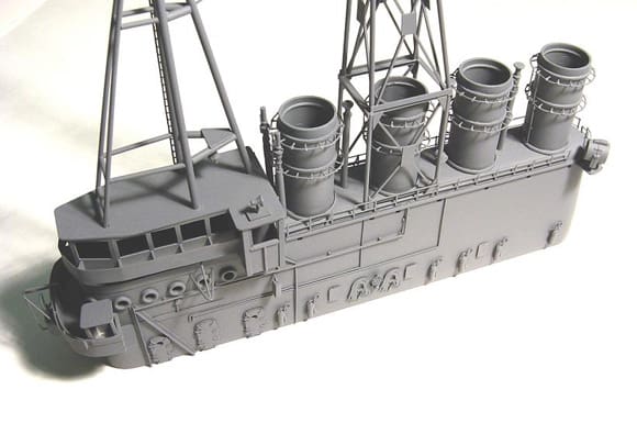
The main section of the ‘island’ is cut out and shaped using a solid block of white pine. After comparing this section to the plans to make sure all was correct, it was time to add the other items to this main section. Holes were drilled for the funnels first using a drill press, and then all portholes were drilled out.
The funnels are actually one half of a spring loaded toilet paper roll holder! Amazingly enough, these are the exact diameter I needed, and have some cool raised details. When scratchbuilding, one must investigate all avenues! Funnels were cut to the correct length, allowing for the depth of the holes already drilled into the bridge itself. I then detailed them out one by one using modified galvanized wire mesh for the grab rings, plastic ladders, and some other parts I had in my stash box. They were then mounted using five-minute epoxy adhesive. Steam vents and the whistles were then added.
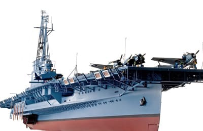
The next step was to build the enclosed command bridge. When Wolverine was first commissioned, this command bridge was open and exposed to the elements. It was later enclosed as depicted on the model. The command bridge enclosure is fabricated from sheet styrene. I built all the walls first, and then cut out the window openings where clear plastic would be applied later after paintwork was complete and figures were added. I then made the roof where the forward mast will be installed. The roof is not permanently attached yet. Next, the RDF platform was added, again using styrene product. Stairway to the command bridge is etched brass. Other items are cast metal.
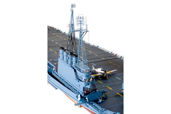
The next step in the island assembly is the two masts. Wolverine started out with just the forward mast with an early version of air search radar on the very top. The navy attempted to add other radars to this forward mast assembly, but found that neither the mast nor the supporting island assembly would support any more weight. Therefore, the second mast was added to accommodate more radar assemblies, and the island was strengthened using steel angle iron, visible on the port side of the structure. Late in the Wolverine’s career, both masts were removed and a single, heavy-duty steel pole mast was installed. Getting back to the two masts, I was fortunate enough to have detailed photos of both of them. Construction of the masts involved the use of styrene rod, strip and angle stock.
The radars are made from galvanized wire mesh, modified etched brass parts and nylon netting. The forward mast was built directly on top of the command bridge roof, while the aft mast was built on the island itself.
After all looked good, final paintwork was done and the roof on the command bridge was attached, after figures were installed inside. Other details were then added such as fire hoses, extinguishers, porthole rings, valve wheels, outriggers, searchlights, railings, etc.
Final assembly
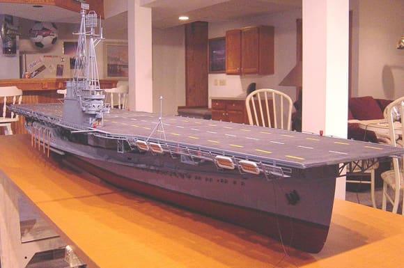
Having completed all three main sub-assemblies of the ship, the hull and main deck, the flight deck, and the island assembly, it was now time to bring it all together. The flight deck was joined to the hull assembly first. I had previously dry fitted these two assemblies together to make sure alignment was correct and that all fitted well. The flight deck is not actually glued to the hull, it is dry fit. Its own weight holds it in place. The island was then attached to the flight deck using epoxy adhesive. The funnel uptakes were then added. These are fabricated from a mould I made and are cast in resin. Other small details are then added such as fuelling stations, arrestor wires and yielding bars, foam generators, more fire extinguishers, etc. Finally, the ship was rigged using 0.010 and 0.020 rigging cord.
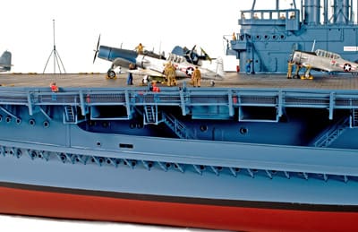
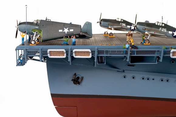
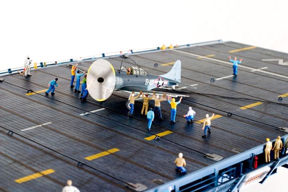
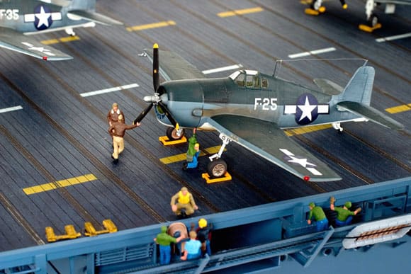
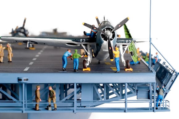
Aircraft and Figures
The final touches on the replica of the Wolverine would be the addition of the aircraft and the figures. Hasegawa and Academy kits were used for the aircraft and the figures are from various manufacturers, modified to fit the period of the USS Wolverine, circa 1944. Some members of my local IPMS chapter agreed to produce the figures and aircraft after I had approached them to do so. Their assistance was invaluable, and I was happy they agreed to help. After their work was finished, I then placed the aircraft and the figures in positions that are believable. I had much fun doing this!
Epilogue
The replica of the USS Wolverine comprises some 4,000 individual pieces and over 1,500 man-hours to produce. I was happy that the project went as well as it did. The replica will be donated to the Kalamazoo Aviation History Museum, where it will remain on permanent display. Thus, an obscure chapter in the history of US Navy ships will be preserved for all to see.
About the Builder
Bill Waldorf was born in Denver, Colorado in 1953 and started building models at the age of seven. He then moved to Buffalo, N.Y., where he spent his formative years. He then moved to Michigan in his early 20’s, where he still resides with his wife, Barbara. He has one child, a daughter, Sarah, who will soon be 18. Mr. Waldorf is a contractor in the residential construction trade. He has been scratchbuilding large-scale model ships of the WW2 era over the past several years. Most of his works go to museums, for all to see. Some of his works are on display at the National D-Day Museum in New Orleans, La, the Patriots Point Museum in Charleston, S.C., and the National Naval Air Museum in Pensacola, Fla., to name a few. Bill is 52 years of age and has been a model builder for over 40 years. He says he will plan to build ships as long as he can, and looks forward to more endeavours. We hope so!