USS Kearsarge
DR MARCUS ROOKS converts the Revell plastic kit
 Article continues below…
Enjoy more Model Boats Magazine reading.
Click here to subscribe & save.
Having successfully completed the conversion of Revell’s HMCS Snowberry to steam propulsion and proving that it was possible, I was keen to embark on another project using experience gained from this. There were some aspects of that exercise with which I was not altogether happy, chiefly concerning the steam plant itself. The engine itself was unreliable and the use of an externally fired boiler was not very practical if the truth be told.
So, it would not be unreasonable to have a go at constructing a purpose built and designed plant for another model. I could have retrospectively fitted HMCS Snowberry but the desire for a totally fresh challenge was too great. The Revell USS Kearsarge was in the collection of unmade models, so the project was underway.
Some ships go through their whole history without ever becoming well known or notorious and USS Kearsarge would have had a similar fate except for one particular incident as she is remembered for sinking the CSS Alabama in 1864, the Confederate commerce raider.
USS Kearsarge was a Mohican class sloop of war and was laid down at Portsmouth Navy Yard under the 1861 American Civil War emergency shipbuilding programme and was launched on 11th September of that year. She was commissioned into service on 24th January 1862 and was dispatched to European waters to hunt for Confederate commerce raiders. Article continues below…
She helped with the blockade of the CSS Sumter in Gibraltar harbour, eventually forcing her abandonment. However, a new British built commerce raider, the CSS Alabama, was commissioned in the Azores around that time. By June 1864 USS Kearsarge had been hunting the CSS Alabama for almost two years from the Outer Hebrides to Cadiz and eventually managed to corner her in Cherbourg harbour (in France) whilst refitting after sinking 65 Union ships. On 19th June 1864 CSS Alabama left port on her last voyage to face USS Kearsarge.
CSS Alabama opened fire first with both ships circling each other in an attempt to gain an advantage. USS Kearsarge was hit in the stern post part of her hull but luckily the shell failed to detonate, otherwise the outcome could have been totally different. Also, USS Kearsarge had had additional armour fitted over her vital areas so she was better protected and was able to delay firing until the range was less than a thousand yards and within an hour CSS Alabama had been reduced to a burning wreck.
Her captain struck his colours and sent a boat to USS Kearsarge with their surrender. Most of her survivors were picked up by USS Kearsarge but some (including Captain Semmes) were rescued by the British steam yacht, Deerhound. The battle had been witnessed by a number of vessels as it had been actually been advertised in advance as Captain Winslow of the USS Kearsarge had invited CSS Alabama to do battle, so avoiding possible internment of the ship. The action is commemorated by the US Navy by a battle star on the Civil War campaign streamer. Article continues below…
USS Kearsarge spent many further years on active service which came to an abrupt end on 2nd February 1894 when she was wrecked on a reef off Roncador Cay, off the South American coast. Some artefacts and relics from her are on display at the Washington Navy Yard Museum. (This is an excellent museum, situated within an active naval establishment. It is on the Washington metro line – Editor)
The kit
Now that we have dealt with the full size USS Kearsarge we can turn our attention to the miniature version. The 1/96 scale Revell kit comes in one of the biggest boxes that I have come across. However, the contents are not quite in the same league, the hull being moulded in two halves lying in a diagonal compartment and the other parts in two sealed bags together with the rigging and decals etc. I have since discovered that this is not the hull from the original 1960’s kit and it would appear to have gone through a number of changes since then. Article continues below…
The original hull dies were modified to produce her opponent, CSS Alabama, and were subsequently re-modelled back to USS Kearsarge and this is the version in the kit. A number of the parts had quite extensive flash which could possibly be accounted for by the age of some of the moulds. The instructions also needed a certain amount of interpretation as clearly some of the fittings did not match the drawings. I often wondered whether or not some of the drawings and photographs actually referred to CSS Alabama as they clearly did not correspond to USS Kearsarge. I have a second kit in reserve and the thought has crossed my mind as to the possibility of conversion to CSS Alabama, anyway we shall have to see.
The plan was to install a steam plant and fit radio control. I had recently converted Revell’s HMCS Snowberry to steam propulsion using a proprietary brand of steam plant but I could see immediately that I would have to use a different approach with this model. Although the hull was nearly as long and was quite deep, there was limited height below decks precluding the use of a proprietary steam plant, so I would have to make my own.
This was the plan and as often happens, things did not go to plan! Over a year I tried in vain to fit such a steam plant starting with a simple vertical fire-tube boiler and a single cylinder oscillating engine. That configuration worked well, but it did not have enough power to pull the skin off a rice pudding!
A different steam plant
So, it was then decided to make a much more workman-like plant, so I designed and built a nice vee twin cylinder oscillator. This fitted below the deck very well and worked like a charm, but it was the boiler that caused the problems. For this, I had constructed a centre flue copper boiler and a custom made gas burner. This unit worked well and powered the engine adequately, that is until the centre flue suffered a fatal collapse which produced a back fire and damaged the hull. It was at this stage that a complete re-think became essential, and regrettably, despite the amount of work done thus far, I decided that steam was not really feasible. However, the engine will not go to waste as it is being retro-fitted in HMCS Snowberry.
Electric propulsion?
It was now decided to fall back on the more usual conventional electric power as steam was apparently a ‘no go’. The rest of the basic model construction would now proceed as planned and I do not propose to write a ‘blow by blow’ account of Kearsarge’s construction. Readers have much more skill than I do when it comes to making plastic models so I will concentrate on the principle modifications that were necessary to make the model properly functional.
Modifications
So without further ado let us make a start on the kit and unusually for me, I actually started first on the hull! USS Kearsarge’s hull comes in two halves which fit together quite well and include moulded copper plates and other fittings. When cementing the halves together make sure enough cement is used to make the seam watertight. As with previous models, I covered the seam with a strip of thin polystyrene, thus both enhancing watertightness and strengthening that seam. Thin clear polystyrene sheet was cemented behind the portholes to represent glazing as open portholes are not really suited to on the water operations!
The hull has many similarities with that of HMCS Snowberry, one of them being the very thick and out of scale keel. Where it does differ is that the rudder is fixed in place, which is of no use to us! The rudder support is also fixed to the keel with a skeg thus producing an enclosed propeller space, thus preventing direct access to where the propshaft tube will be fitted. It is worth using filler liberally to strengthen the joint between the two hull halves in this area and there was a moulding deficiency at the stem which needed repair.
Rudder
Using a junior hacksaw, the rudder was removed and a new profiled version created using files and fine sandpaper. In hindsight it would have been a good idea to also construct and install a new, larger propeller to improve the functioning of the rudder. The ship’s stern needed some attention as the stern plate is about 1/4 inch thick and the new rudder tube is made from 1/8 inch brass tube. Using files and sandpaper this area was also tapered from the propeller to approx. 1/8 inch.
On the full size vessel, the rudder pivoted on simple hinges and here I followed suit. The straps are made from strips of thin copper sheet approx. 1/8 inch wide. You will need to prepare six strips, each about 1 1/2ins. long. These are over-scale, but practical considerations have to be taken into account with this working rudder and in any case they are submerged and out of sight when the model is on the water.
Next, a length of 1/8 inch brass tube about 2 inches long was required. The strips of copper were bent into U shapes around this tube, but leaving 1/4 inch between each of them. They were then soft soldered into position. The tube was then cut into sections, each including a strap, ends rounded and trimmed to length, except one which had a longer length of tube. The straps were then arranged on the rudder blade and hull as shown, endeavouring to make a nice neat appearance. A length of 3/32 inch brass rod was passed through the straps to centralize the whole thing whilst checking that the rudder could rotate freely. Once satisfied, the straps were superglued in position. If you are able, I would also suggest securing them in place with some 12BA screws.
The rudder crosshead was made from a cut down redundant output arm from a servo and superglued to the rudder shaft. You must check that it does not prevent the rear deck from seating correctly. The lack of adequate headspace was the bane of my life during construction of the model and there was barely enough room to accommodate the miniature rudder servo under the deck.
The rudder crosshead was connected to the servo by means of some 1/16 inch brass wire with flats filed on each end to accommodate plates. These are soft soldered in place and drilled to suit the steering arms and the whole thing is held in place with 12BA screws. The linkage had to be done this way as there was just not enough height to use the usual rod, bent to shape. The micro-servo is placed aft of the engine on a mounting made from styrene sheet. It is always best to check that any rudder linkages on any model give as much movement as possible. You can always reduce the degree of movement, but increasing it later can be a bit of a pain.
Propeller and its shaft
A propshaft was required as of course the standard static model kit doesn’t include a rotating propeller. The outer stern bearing support was machined from brass and drilled 1/8 inch to accept a 1/8th o.d. tubular brass shaft. The outer bearing was pressed home into the hull and glued in place. Once correctly positioned, the inner support bush was slipped in place over the shaft and also glued in place. Polystyrene body putty was liberally smeared around the inner hull surface area to strengthen these joints and ensure complete watertightness.
The propeller also required modification. The boss was opened to 1/8 inch and a piece of 1/8 inch o.d. brass tube inserted and superglued in place. This would then accept a 3/32 inch o.d. inner shaft that sides inside the 1/8th inch brass tube shaft. Yes, a bit ‘Heath Robinson’, but it works fine.
Painting
At this juncture the hull bottom was painted copper, leaving the natural black plastic untouched, except for a little touching up here and there. The hull striping required careful masking, but it was difficult to obtain a neat result at the bowsprit area due to the tight hull curves. It is best to paint the various parts of this model as you progress, if only for convenience. I have to admit that I found the colour scheme somewhat over-complicated and the four different shades of brown were reduced to just one.
USS Kearsarge was painted as she would have appeared on the day she was launched, i.e. pristine and bright, as I am not one of those who go for weathering to make the ship look battle worn, but the choice is yours.
The finished result is quite fetching with the red water line really setting off the hull. Next up, was access and the powerplant.
Access
As previously explained I ended up with a straightforward electric drive but whether the model is steam or electric powered, the same problems concerning access still exist. USS Kearsarge has an abundance of rigging which will interfere with deck removal, and cannons projecting through gun ports will also cause trouble.
This is where I would like to diversify a little. Over the years, the modelling community has bee very friendly and helpful. After the appearance of my article on HMCS Snowberry I came into contact with Glynn Guest, who was a veritable mine of useful and practical advice.
Anyway, Glynn kindly gave me a copy of an article that was in a Model Boats issue from 1968 which described the motorising of the then new Revell kit. It was interesting to see how that writer had tackled the question of access as he obviously faced the same problems. His solution was to cut the hull in half horizontally at the waterline, thus making the complete upper part of the hull removable. This was I felt somewhat drastic and my solution is a little better and easier.
The deck already comes in three convenient sections, fore, main and aft. Removing the main fore deck is complicated by the bowsprit going through it. This was dealt with by cutting off a section of the deck, including the said intersection. A styrene support shelf is glued to the cut end and the small piece of deck and bowsprit were then permanently cemented in place on the model.
The raised fore deck was cemented permanently to the main deck section, thus they can be removed in one piece as the mid-deck They were joined using the rear support as supplied with the kit and the fore mast and kitchen stove chimney can also be cemented to both decks, but between the two of them the deck needs to be adequately supported. If necessary some extra intra deck supports made from styrene strip can be cemented in place underneath it.
This mid-deck section needed to be totally removable and I began by cementing styrene strip ledges to the free ends of the fore and aft decks. These provide extra support for the deck and 10BA screws hold the deck firmly in place.
The cannons also have to be removable so the deck can be extracted. The beam cannons are held by spigots which allow them to be readily removed and the large swivel canons are also on spigots, plus the forward cannon is held on the main central portion of deck so is also not a problem, but the aft cannon is positioned on the rear deck but overlaps the centre section. It is possible to rotate that cannon out of the way when the deck is removed, but if this not possible for you, then make sure that it can be easily removed completely.
There are numerous belaying pins etc. on the inside bulwarks of the hull, so as many as possible of these were made removable so that the deck could be manoeuvred around those remaining.
That was the easy part! Now we come to the difficult part, namely how to deal with the rigging? When the rigging diagram is studied it is clear that rigging from the various masts is secured to the hull sides in ‘the chains’ and also to different deck sections. Thus if we follow the correct design plan it will not be possible to remove the centre deck section as it will be held fast by the rigging.
The rigging was simplified a little by omitting some of the sheets (I hope that I am using the correct terminology here!) that are connected to the deck and that certainly made life easier. It might be possible to remove the masts before removing the deck, however, we would probably end up with a terribly tangled rigging. Also, the masts would have to be lifted several millimetres before being removed and once again would be held firmly by the rigging and if we allowed enough slack in the rigging it would look dreadful, so how best to proceed?
After some thought, I had the notion that the chains on the sides of the hull could be made removable using metal locating pegs. This was the way to go as it is a quick and simple operation now to remove them from the hull.
The fly in the ointment is that the locating pegs on these are thin and flimsy and the horizontal bracing pieces over the locating pegs had to be thickened locally with styrene strip. The existing plastic pegs could then be removed and the thickened sections drilled for new locating pegs of 1/16 inch diameter brass wire. Short lengths were superglued into each hole, matching a corresponding hole in the hull and then each assembly could be easily attached to the hull side. By having the locating pegs ‘spring’ into the hull, each assembly is held snugly against the hull.
The rigging which is quite typical for that era is very complex, so as already suggested it is best to try to simplify matters to aid deck removal. I thought at times that Revell had lost the plot with the rigging diagrams, but eventually could make sense out it and even got some of it to work! I also learned quite a lot about how a sailing ship functions which I found quite interesting.
In the end, virtually the whole rigging as described was installed, but it took an age to complete. Rigging the Airfix Great Western was tricky but that was a piece of cake compared with Kearsarge. The purists may not be happy, but to me it looks fine and as far as I am concerned it is only myself that I am trying to please. The black cord supplied would not fit the eyes provided, so larger eyelets from the spares box were utilised. Some of the moulded eyelets on the bowsprit had come off whilst it was still on the moulding sprue, so these were also replaced with spares or fabricated from flat sheet and it took a whole morning just to rig part of the bowsprit. In hindsight, I suspect that some of the rigging diagrams may refer to the CSS Alabama’s rigging.
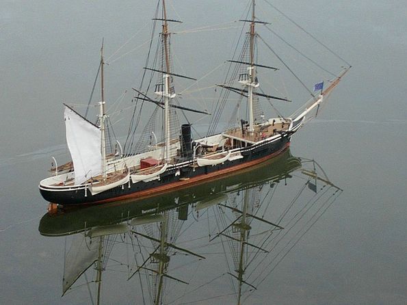
After all that, although there was a plethora of ropes and pulleys I still thought that it looked somewhat naked, so decided to add some sails, or rather just one sail, namely the mizzen sail. This was cut out of an old white shirt with the additional hope that it would help to stabilise the model when sailing.
Motor and battery
Returning to the engine room, an MFA Torpedo 500 motor was installed, chiefly because it had an 1/8 inch output shaft that corresponded to the coupling end. An inclined platform was constructed from styrene sheet and the motor bracket held in place with 6BA brass screws.
A battery compartment was constructed by adapting the battery strap that was included with the kit. This was turned upside down and cemented to the hull bottom. This held two D size standard torch batteries. End caps were fabricated from styrene sheet and spring contacts made from thin brass sheet. There was only room for the two batteries, which meant 3 volts in total although the motor was rated at 4 to 15 volts. As it so happened, this was just right for this model.
Simple on/off switches accessible from the outside of the hull are the means of powering-up the model as this reduces the number of times the deck has to be removed, that only becoming necessary for changing the batteries. These switches were housed in an additional deck mounted skylight installed when attempting to get the steam plants to work and it doesn’t look out of place, even now. The radio receiver and batteries are simply placed loosely in the hull. As with HMCS Snowberry, the kit comes complete with a crew and there are several sailors in different poses with a comprehensive painting guide. These were dispersed around the deck in a realistic manner and really do add realism to this model.
Sailing
When ready to sail, USS Kearsarge only needs the on/off switches to be activated and away she goes. In operation she has performed very well, being nice and stable with a decent but not excessive turn of speed. The motor does not need excessive rpm to provide adequate thrust and 3 volts is about right. The sail was used more for effect than anything else but does help stabilise the model. (Running motors on lower voltages than normal to achieve a scale performance, is something that Glynn Guest has positively commented on within this magazine – Editor).
Conclusion and the future
In the end the model turned out well although I have to admit not as planned. The fundamental problem was lack of interior vertical height and volume to accommodate a suitable boiler. I am not saying it is impossible to fit a steam plant as I was close to success and constructing a third boiler may have been the answer, but the failure of the second boiler, did rather put me off!
Looking at available kits, a 1/350 scale Bismarck is now under construction, but once again although it is a large model, it lacks the necessary height and interior volume. I fear that most similar ships will be the same, except possibly an aircraft carrier. The 1/350 scale Agaki aircraft carrier (converted from a battlecruiser hull) would indicate that there may be enough height and volume, so I am already thinking of a centre flue boiler coupled to steam turbines. This would be rather exotic (especially after my recent failure!) but all big warships of that age were fitted with turbines and not reciprocating engines.
The current best UK price for the Revell USS Kearsage is around £23.
Main interest is scale scratchbuilding but I build kits as well! I live in South West Surrey near the Sussex border

