David Heaps builds a model of this Scottish Ferry based on a James Pottinger plan
Background
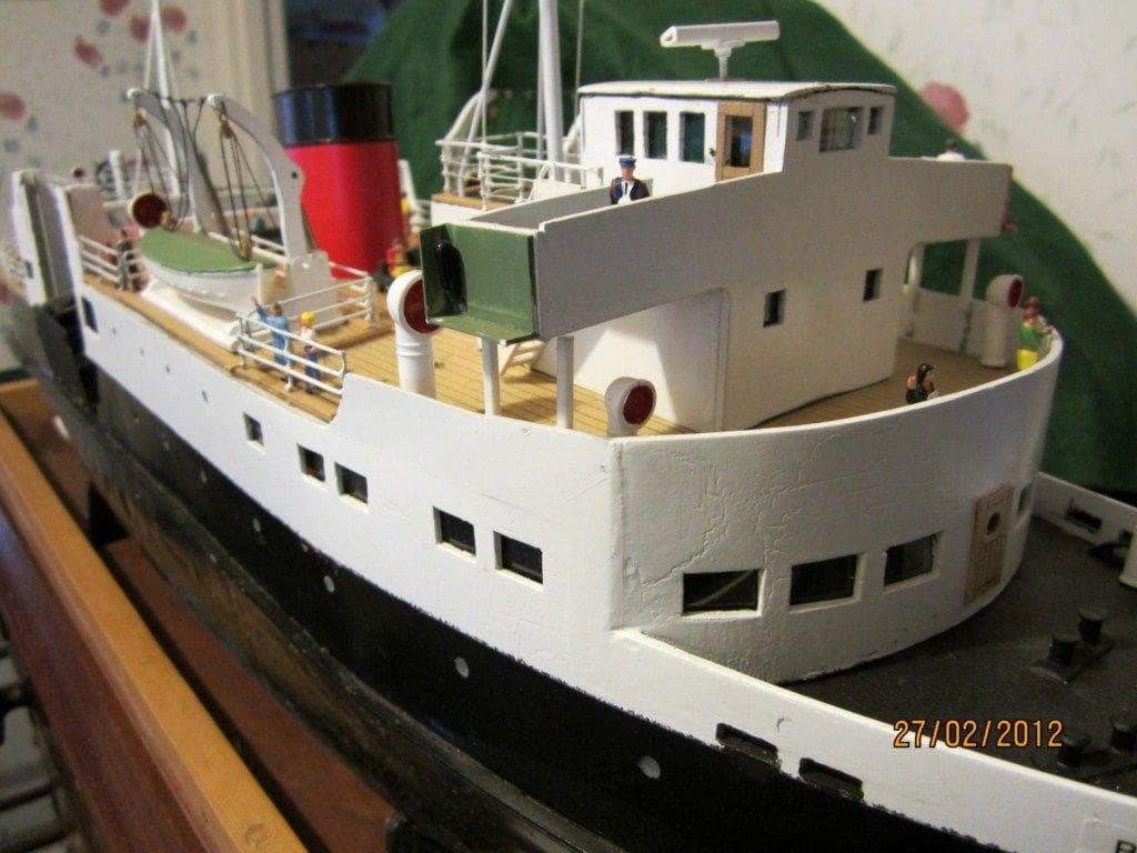
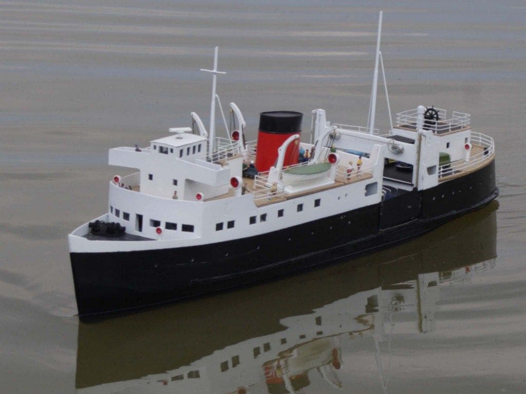
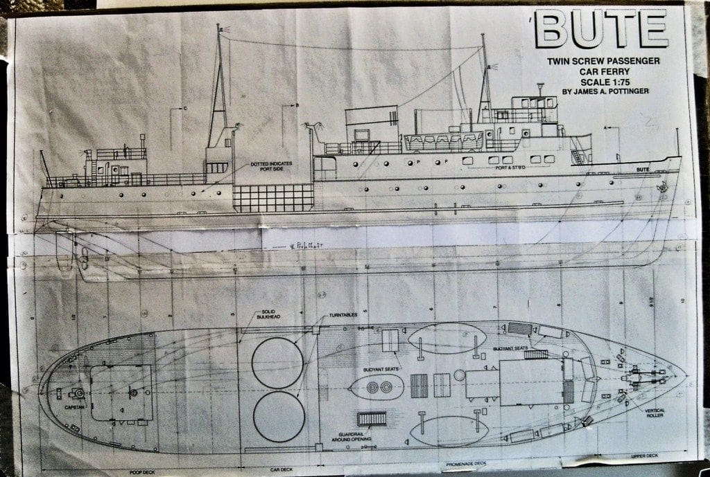
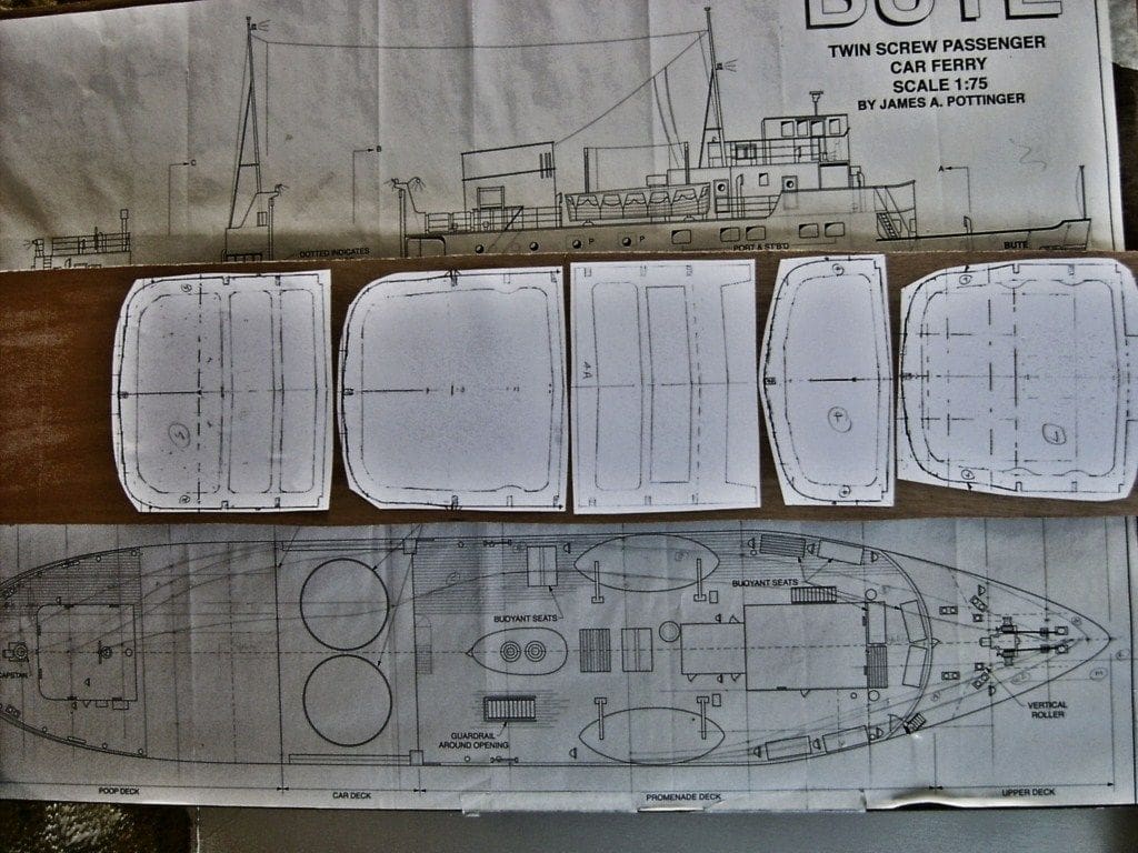
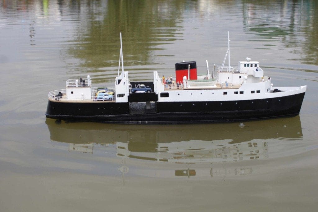
TSMV Bute was a Clyde car and passenger ferry of the mid-1950’s. My attention was drawn to this vessel by a very informative article by James Pottinger in the April 2007 edition of Model Boats magazine. Not only was the article comprehensive, but the magazine provided us with a free full size plan for a model, conveniently sized at 30 inches long.
Enjoy more Model Boats Magazine reading.
Click here to subscribe & save.
My interest was further heightened by the fact that the ship had a vehicle lift about one third distance from the stern which gave me the opportunity to include a radio controlled electro-mechanical system for it within the model. The vessel had twin propellers, partly to keep the draft minimal when operating in shallow waters, but also to enable the captain to leave a quayside without moving forward by putting one of the propellers into reverse, thus rotating the ship on its axis. I was able to make the model do the same by including a further electro-mechanical system within it.
Design
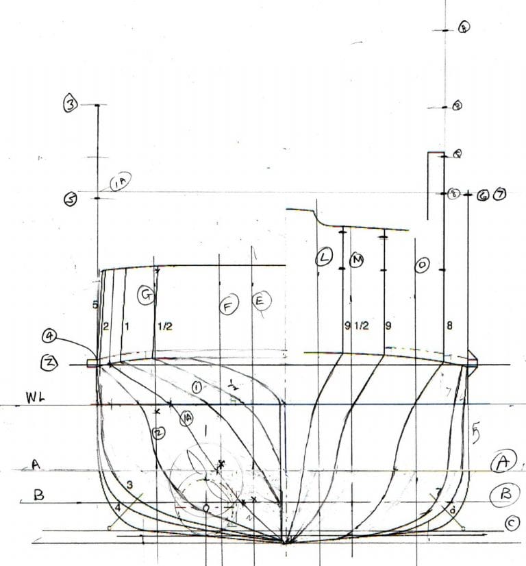
From previous experience of building scale models, I knew that it was very unlikely that a hull with a true scale depth below water would provide a stable model as the topsides of a model are usually much heavier than those of the prototype. I therefore set about considering how much deeper I should make the hull. The result is shown in Photo 1 where I have cut James’ plan at the waterline and stuck a piece of paper behind the plan to add 25mm of depth. Join all the lines in a sensible way and you have a new side elevation. It’s as simple as that! Redrawing the revised cross sections was more difficult, Photo 2. These shapes were checked by drawing many vertical and horizontal sections. Overall, this is a simple means of increasing the draft without redrawing the whole plan.
Hull
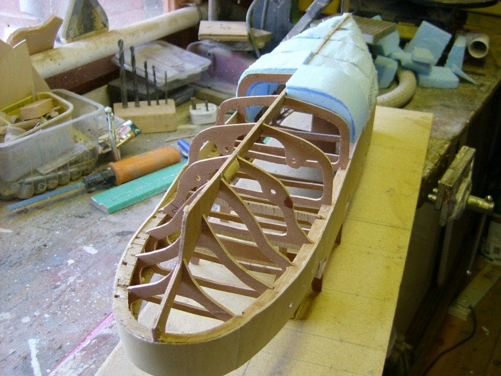
The hull started from a simple framework of a keel, cross sections and plan members which were cut from 3mm plywood. The keel shape was copied from the side elevation and the cross section frames from the revised drawings. However, even the revised plan only showed one half of each cross section and of course you need both sides. With a computer and printer/scanner unit this is easy, as to obtain full sections all you need do is scan and use the mirror image facility to give you the other half. You can then make as many copies as you want and stick them as templates to the plywood, Photo 3.
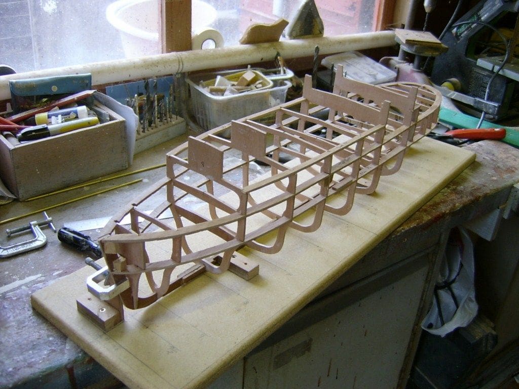
I decided to build the hull right way up as in Photo 4. The process is simple in that you first mark out the keel line and section positions on a piece of 12mm thick ply building board and then position two small blocks against the keel line. The keel is then clamped to these blocks. The rest of the framework was then carefully fitted and glued using quick setting PVA glue and left to set for a day.
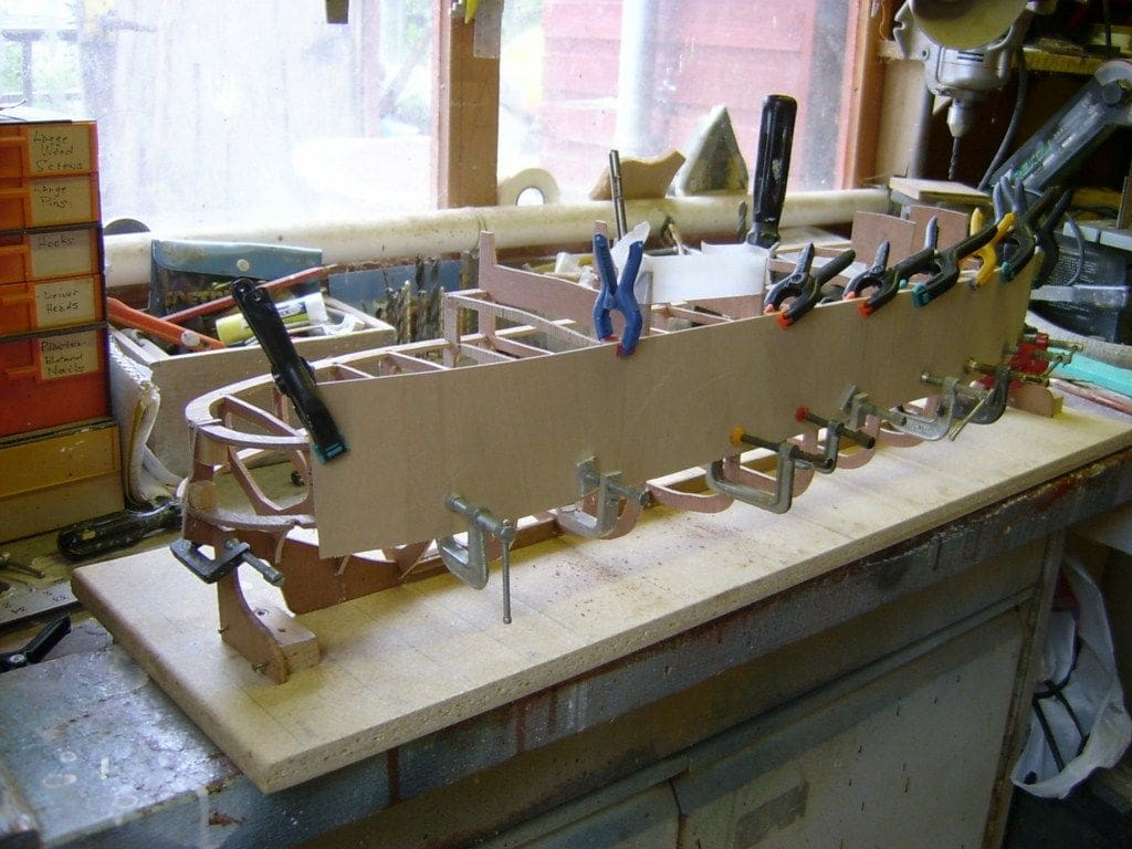
Approximately half of the hull is reasonably flat and those areas were covered in 1.5mm plywood, Photo 5. This was carefully trimmed to meet the stringer and deck edge lines. The remainder of the hull was formed used dense polystyrene foam and GRP resin and cloth.
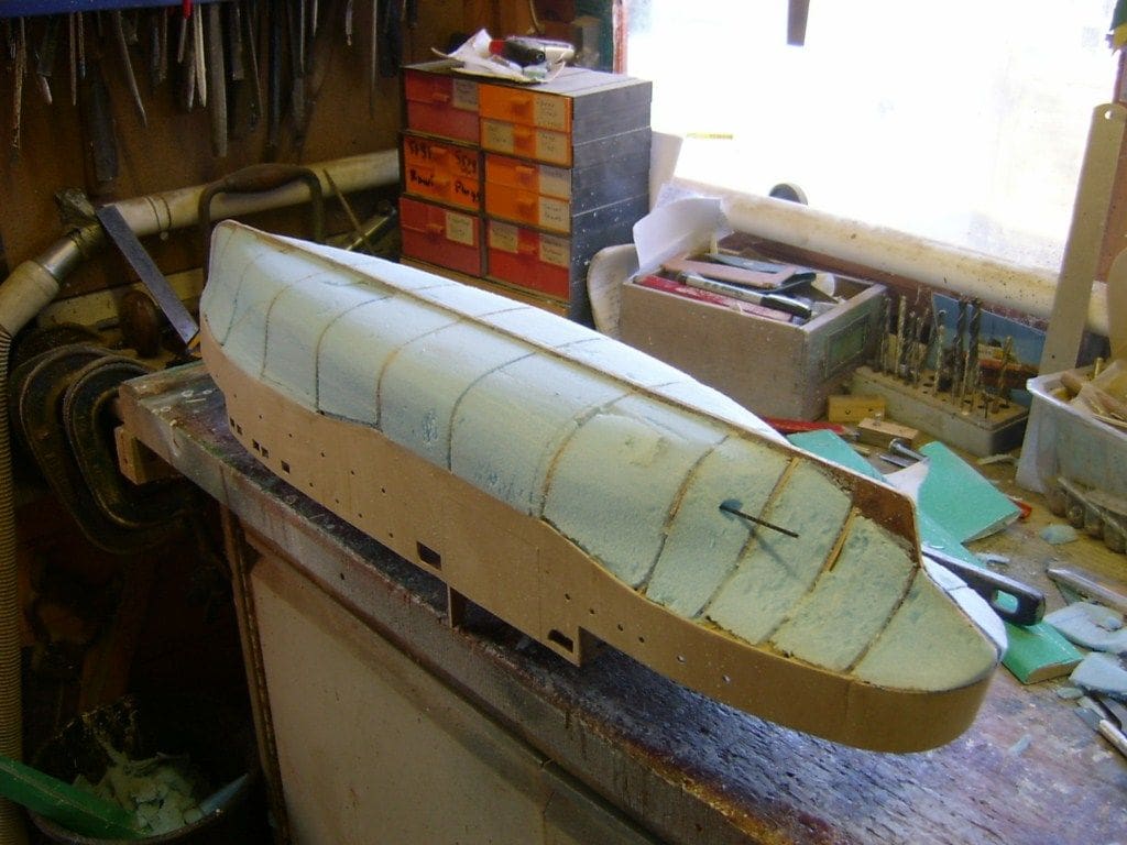
Pieces of the foam were stuck with PVA glue between the frames as in Photo 6. This need not be an accurate job as when the PVA has set, you can then shape the foam both inside and outside with sharp knives and sandpaper as in Photo 7. The foam was then coated with thin domestic wall plaster just to emphasise any bumps and dents, and sanded smooth, thus generally exposing the raw polystyrene foam once again.
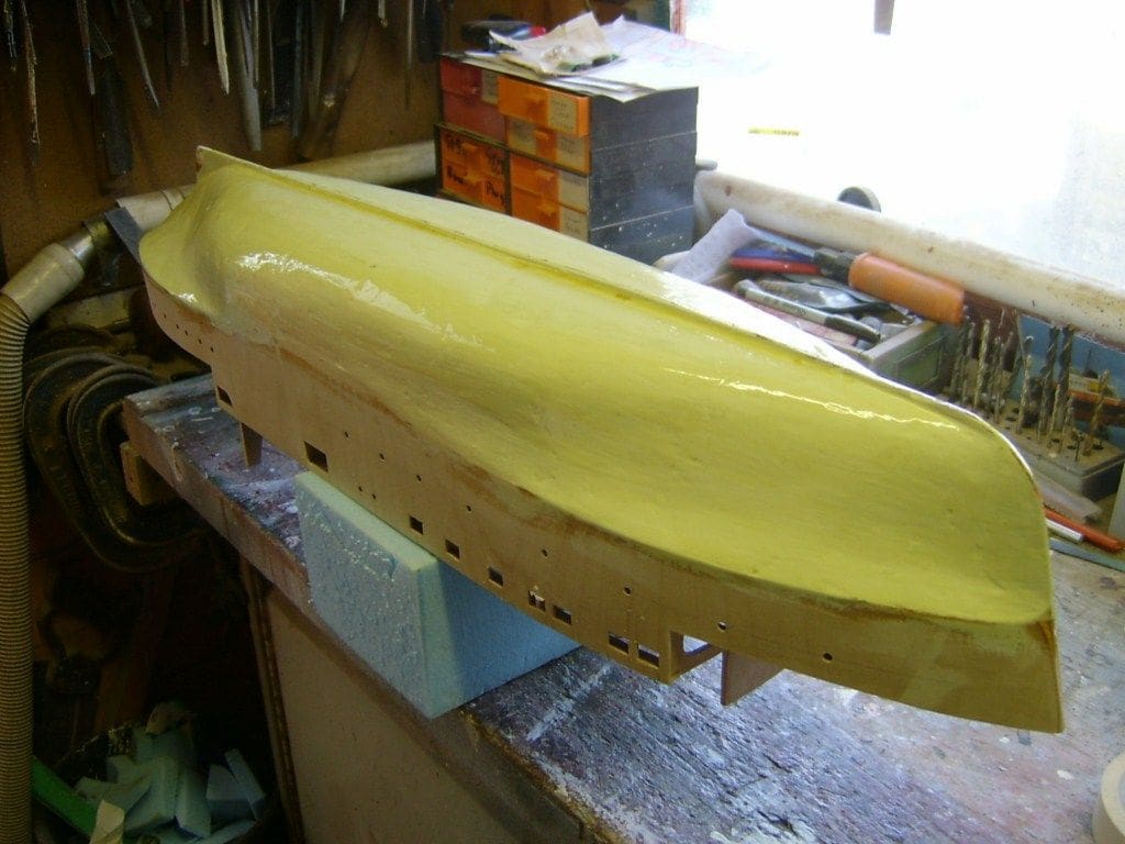
The next step was to prepare the now smoothly shaped hull for GRP coating. You can use epoxy resin, but this is much dearer than polyester GRP resin, so I use ordinary car repair kit resin, but therein lies another a problem. The foam and resin are both polyester based and the GRP resin therefore rapidly dissolves the foam if it can get to it! To prevent this, the foam was painted with three coats of emulsion paint with a light sanding between each coat, Photo 8. The glassfibre cloth in 25mm wide strips was now be applied, well soaked with GRP resin, enabling the smooth contours of the hull to be maintained. All this was then carefully rubbed down once totally cured, any over-sanding also being made good.
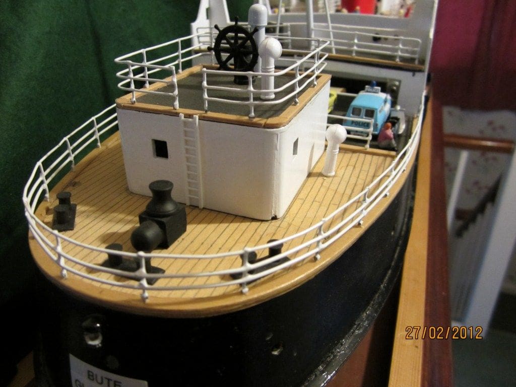
Topsides
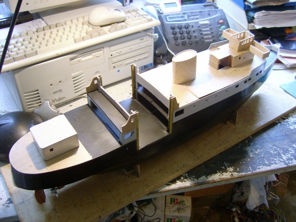
These are made from thin ply glued to the cross section framework, Photo 9. When building the upperworks on any model, you must bear in mind that you have to install the motors, rudder linkages, r/c, batteries etc., plus in this case a working car lift and the electronic equipment needed to control it. Personally, I tend to do all this at the same time when building the upperworks on a model, because proper consideration can be given to installation and removal, earlier rather than later in the process.
Motors and steering
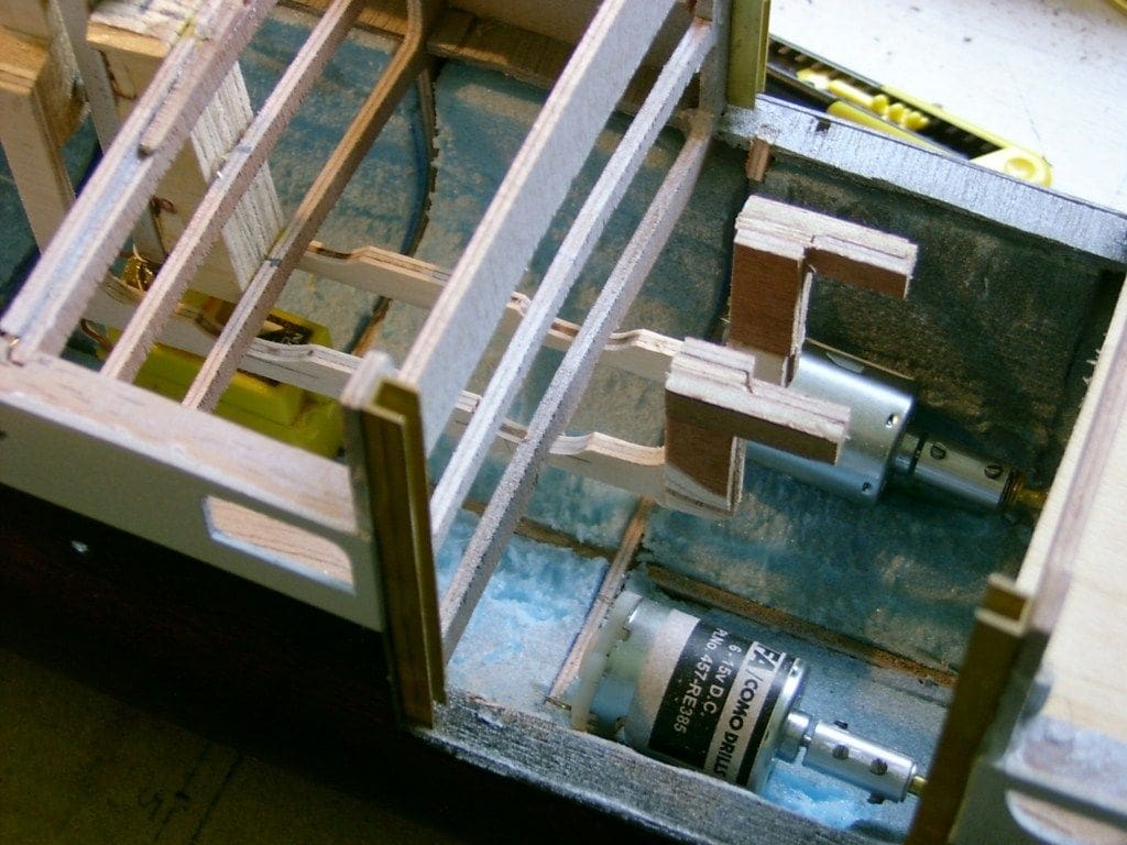
The model is powered by two 385 sized motors as in Photo 10, which are controlled by a single 15 Amp electronic speed controller powered by a 7.2v NiMH battery. The supply to the motors from the speed controller goes through a mixer to allow the propellers to turn in opposite directions. What are the strangely shaped pieces of wood between the motors? Well these are the framework arms of the working car lift and more on that later!
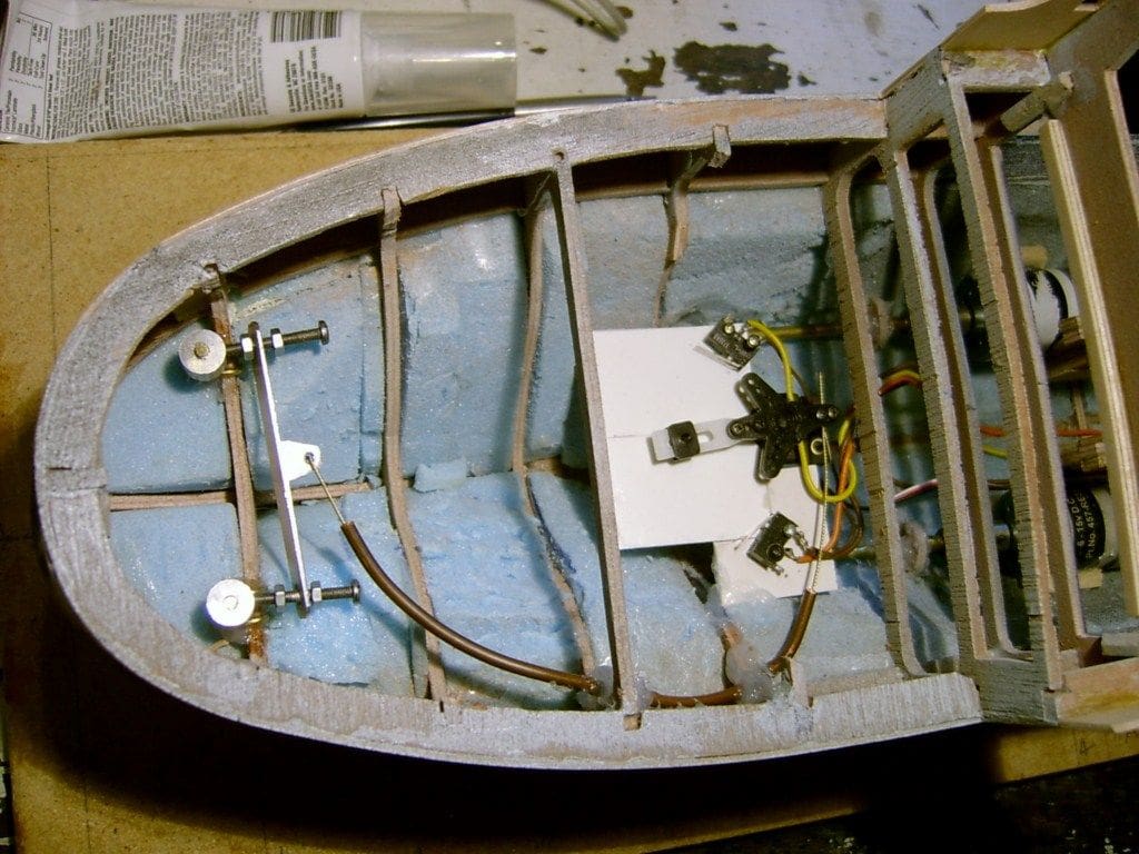
The model has twin rudders which are moved by a medium sized servo via a short cable link, held rigid in a short length of copper tube, Photo 11.
Manoeuvring
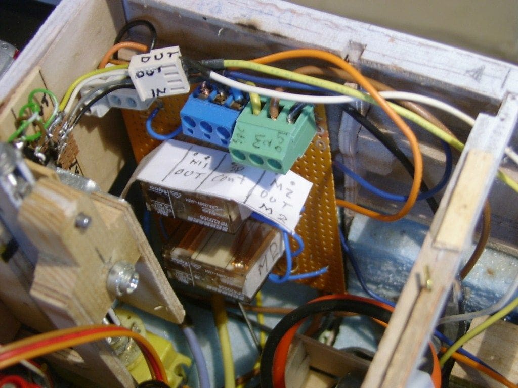
The model is equipped to rotate on its axis without moving forward. This was essential for the full size vessel so that she could easily leave small and often congested piers. Nowadays, such a manoeuvre would be made using bow thrusters, but in the 1950’s ships didn’t have them, so the captain would usually reverse one propshaft to create the required turning movement. In this model, micro switches are positioned close to the output arm of the rudder servo (please see Photo 11 again). During normal steering, these are not activated, but when a rotating movement is required, the fine tuning adjustments and steering stick on the transmitter are pushed to their limits which enables the steering arm on the servo to traverse a bit further than normal, thus activating the micro-switches. This reverses one propeller and the model will rotate on its axis. The actual reversing of the correct motor is achieved by a series of relays positioned in the hull, Photo 12. The details of the circuitry and mechanisms would perhaps be better explained in a separate future article.
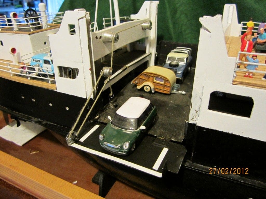
Car lift
This is what attracted me to this vessel. In the 1950’s, cars had to be loaded by crane and this was because the height of the piers was fixed and the height of the ship varied according to the state of the tide. As road traffic increased, a quicker method of dealing with cars was required, but RoRo ferries were not practical unless there were floating piers at the various ferry terminals. Having an onboard lift also enabled two decks to be used for vehicle transport. These lifts usually also had turntables to enable the cars to be rotated so that they could easily drive to a parking place.
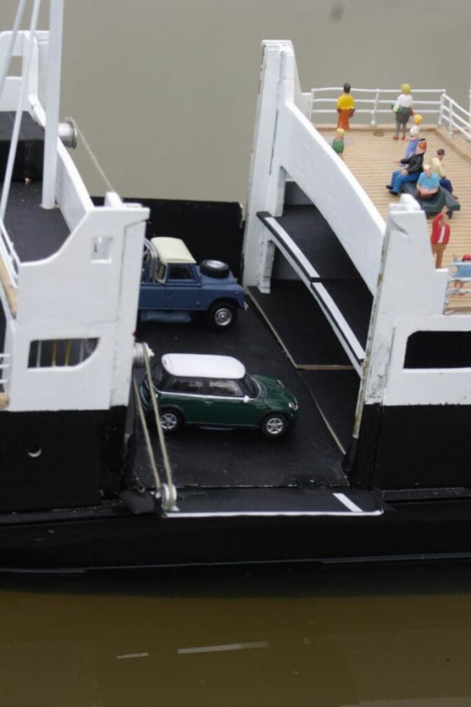
In this model, the lift and the loading lamp are radio controlled and Photo 13 shows the ramp extended and Photo 14 has the lift raised and the ramp partially extended, which would not normally happen at sea of course!
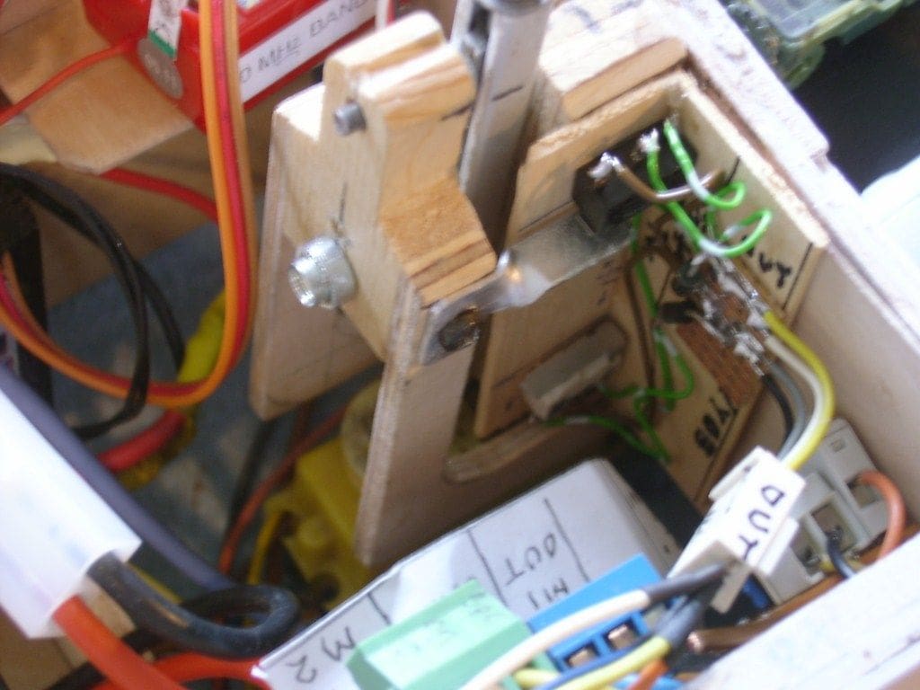
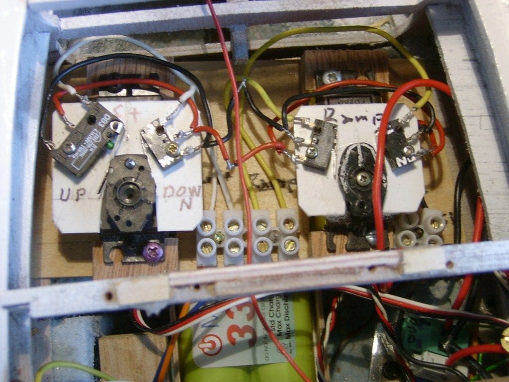
Fitting the mechanisms and the electrical devices into the hull proved to be a challenge. Referring back to Photo 10, this shows the U shaped frame which connects a screw jack forward of the motors, Photo 15, to the lift platform which is fitted on top of those frames. The screw jack consists of a motor and gears from an old servo driving a threaded rod housed in a length of curtain rail, the top of the screw assembly protruding into the funnel which is rather handy! The screw jack is controlled by the left hand servo and micro-switches seen in Photo 16.
Actually making the side loading ramp work was yet another challenge and Photo 17 shows the string attaching the ramp to the small servo modified to be a winch. The difficult part was arranging the string so that the ramp stays in the same position relative to the lift, irrespective of where the lift is. The ramp winch is controlled by a separate servo and switches.
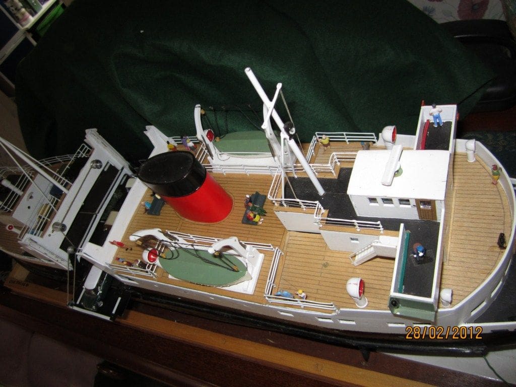
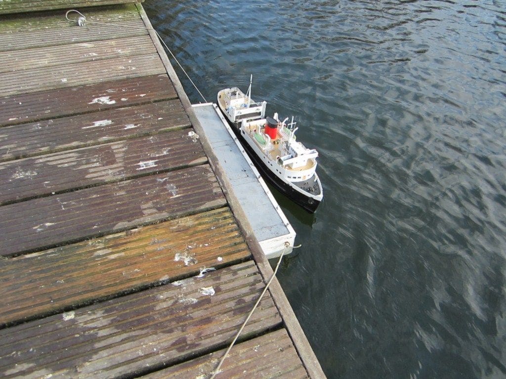
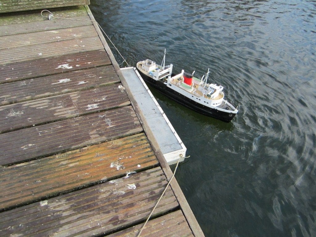
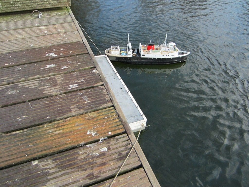
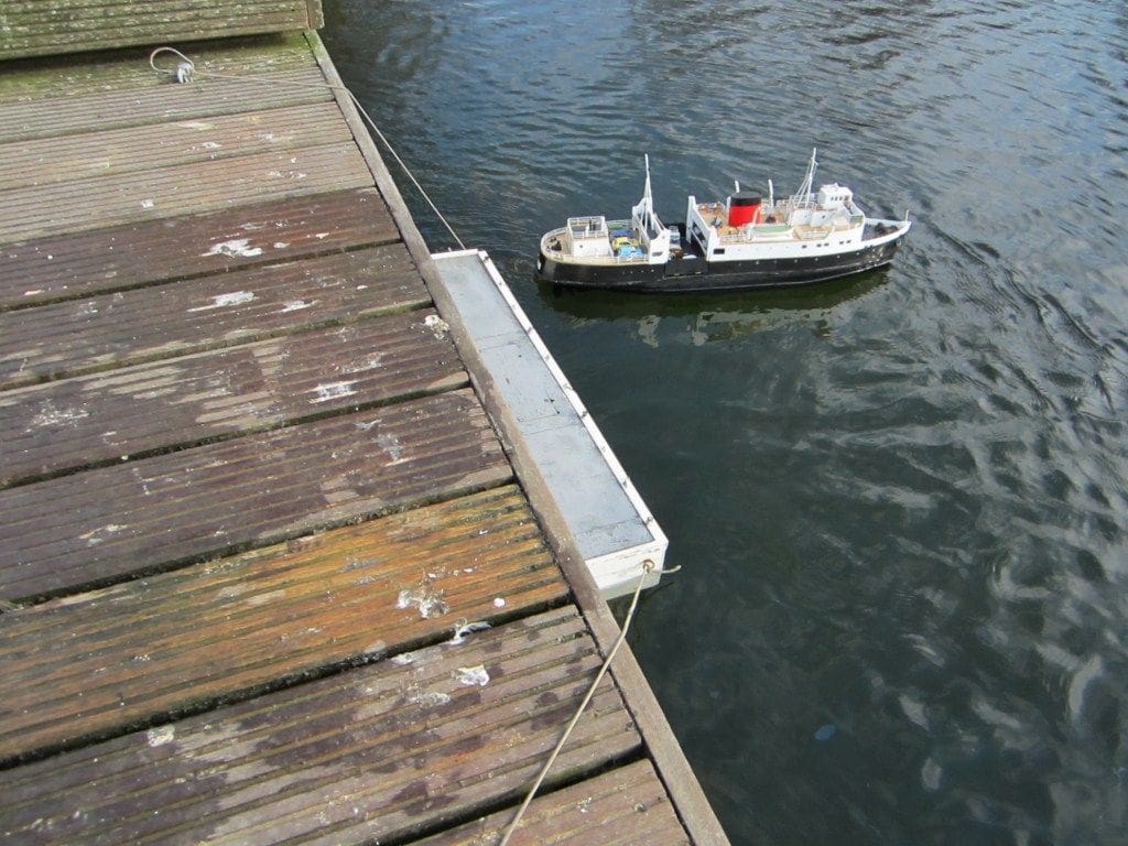
Sailing
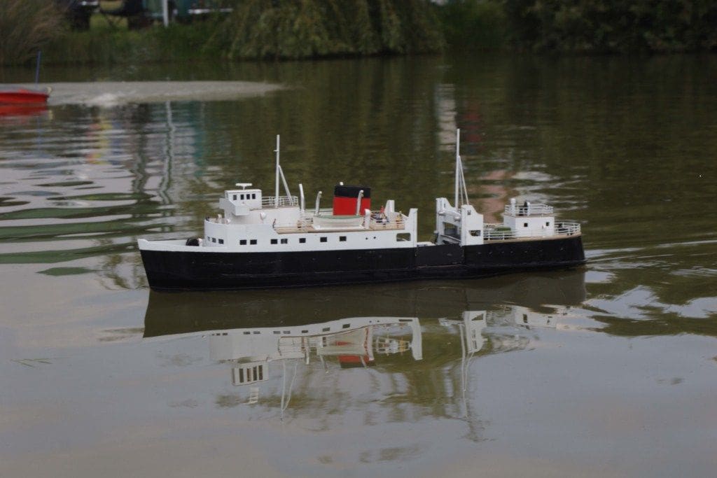
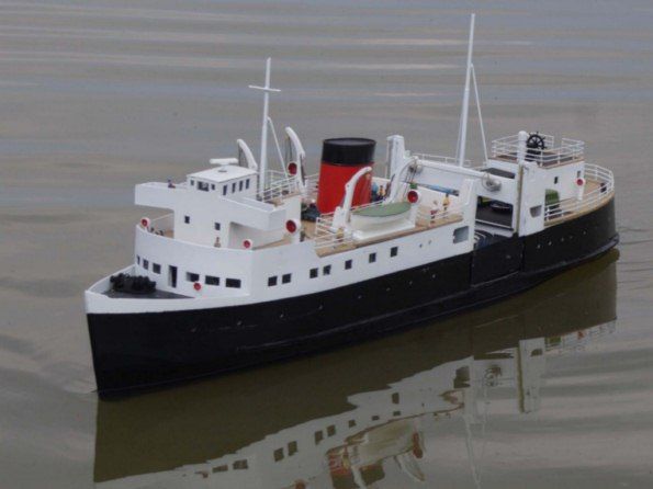
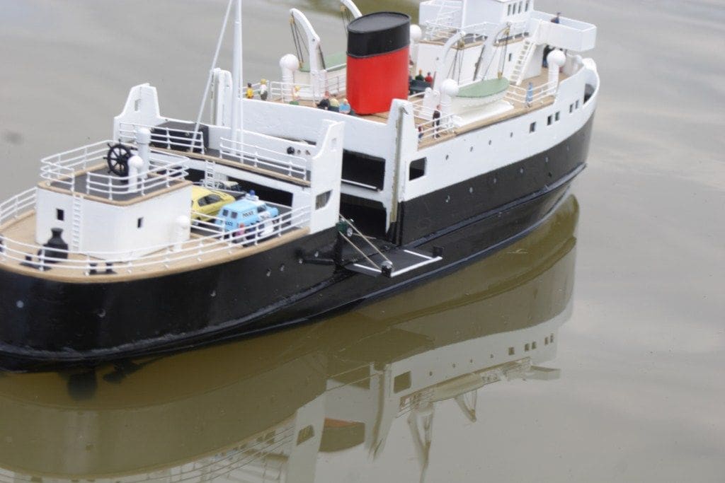
TSMV Bute is an attractive, interesting and conveniently sized model. It is a good sailing model and with the working features is a great attraction at shows. It is stable on the whole, but leans over a little when performing sharp turns at speed, which I guess is to be expected. Turning on her axis, which is best illustrated by Photos 18, 19, 20 and 21 without the use of a bow thruster creates much interest and the operation of the lift and ramp also raises questions as too how it is done by spectators. I hope this has wetted your appetite, not only to build TSMV Bute, but to also consider including working features in your models which can make an r/c model so much more interesting.
TSMV Bute Plan
This was first featured in April 2007 Model Boats, Pages 32 and 33. The article by James Pottinger included pictures of the full size vessel as well as some constructional advice. The two sheet 1:75 full size plan for TSMV Bute is supplied on two sheets, reference number MAGM2035, and is priced at £12.50 plus p/p. Back issues, or photocopies of the article, as well as the plan, are available from MyHobbyStore, website: www.MyHobbyStore.co.uk, or by telephoning 0844 848 8822 between 10am and 4pm, Monday to Friday.