
Wheelhouse
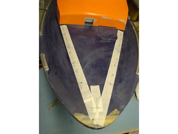
This is supplied as a very strong and even thickness GRP moulding with good clean edges and no air holes, a sure sign of quality. All the required openings needed marking out for the windows, fire valve boxes, top deck/roof and rear opening – so plenty of drilling and cutting required. This is a very dusty business and precautions need to be taken with the wearing of a good quality dust mask and protective glasses or goggles, plus always have a vacuum cleaner to hand! To protect the GRP gel coat and to aid in the marking out process, masking tape was duly applied. To assist in getting the right shaped windows I carefully removed from the Perspex window parts, the inner waste piece of the window frames, which is then my template to draw around for each window opening to cut out and file to shape. The areas on the GRP to be removed were marked in with diagonal lines. I then drilled a 6mm diameter hole near to the inside of each curved corner, allowing for filing to shape later, then armed with a mains operated variable speed drill and a cutting disc tool I proceeded to cut and join up each hole in a straight line – just like cutting through butter. Note that cutting discs do not like bending of any kind or too much heat as they will crack and shatter, so protective goggles even to the degree of a full protective clear visor, is a must.
The same process was carried out for the roof, rear cabin, entrance door, side vent openings and some places on the hull. In all I only used five cutting discs.
Next comes the filing part, first with a medium rough flat and half round file, then finishing off nearer to the required line/shape with a smooth file and glasspaper. The roof part of this task has been made much easier, as the GRP laminator who I congratulate, has laid a very even thickness including the edges, so has made cutting so much easier with no thick and lumpy parts to cut through. This is very important where the flying bridge window frame brass etch needs to be fitted. It’s all just a matter of marking, cutting and filing back to the required measurements. To find the exact position for each opening for the side vent boxes, the inner vac-formings along with the outside etched brass overlays need to be used in conjunction with the plan. Unfortunately this only shows the starboard side which is different to the port side, so I had to look at the photo set to try and work it all out. This can be done by locating where the windows are in relation to the overlays. Once marked out they all need to be cut out square to allow for a snug fit of each vac-forming. These are all superglued in place and then an amount of 5-minute epoxy is spread around them. The front also has a vent that needs to be cut out which could easily be missed without the aid of the photos. The many brass and Perspex overlays, eyebolts, and handrails which I constructed off the model were then glued on.
Enjoy more Model Boats Magazine reading.
Click here to subscribe & save.
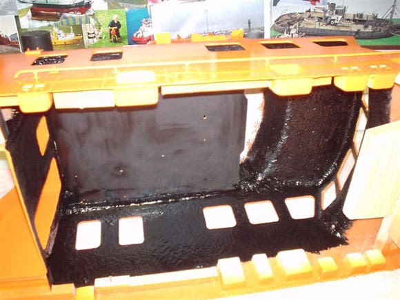
Once all is sprayed orange then the fine etched detail was added – eyebolts, handles and even brass etched padlocks. Also at this stage I decided to paint the whole interior matt black as per the real Severn, including around the rim of each window cut out. See Photos 40 to 52.
Wheelhouse Main Deck and Upper Control Boxes
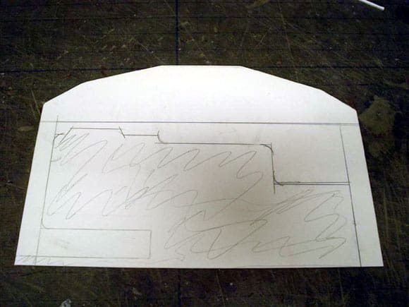
The wheelhouse main deck is a one piece shaped 5mm Perspex sheet with positioning detail etched on for the control panels and side boxes. Once the GRP moulding has been sanded and filed to shape the floor should and in fact did fit exactly like a glove. The position and height of which can only be confirmed by the front control panel and side mast boxes once assembled from the laser cut Perspex parts. I always use Plastic Weld glue for Perspex to Perspex as it’s designed for the job. It is a solvent glue which melts and welds the two surfaces together. Once cured I run around the inside joints, that will not be seen, with superglue as extra strengthening. I also use a flat sheet of glass as a base for assembly, as it has a perfect flat surface. Assembly was very simple as all components are easily identified. The boxes can then be placed in position as per the deck markings, making sure that all looks level and parallel at the sides and top part of the wheelhouse/bridge front. All was then tacked in position and once happy a fillet of P38 was spread all around the underside between the deck and wheelhouse sides. The rear canopy inner wall is another GRP moulding requiring trimming to fit, glued and in my case bolted in position, at locations where they are hidden from view by the rear boxes. All is then fared in and sanded with P38. See Photos 53 to 55.
Wheelhouse Stern Boxes
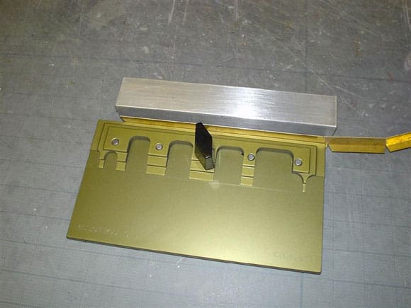
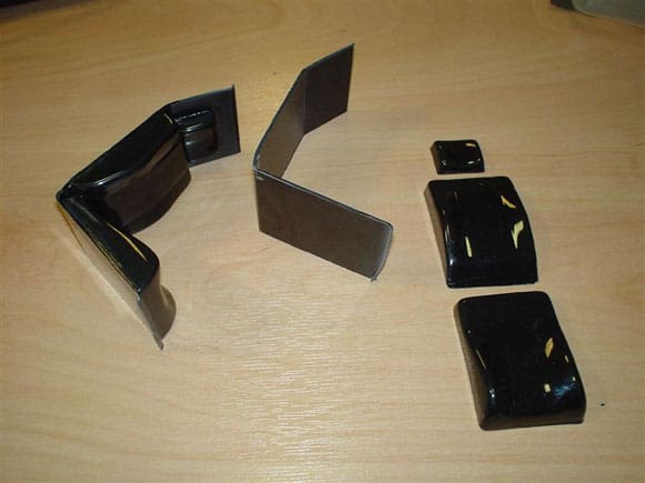
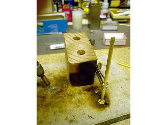
Making these up was a very simple task as they are just a box-like construction. Once again, the various etched markings should face outwards which gives a clue as to their positions and eventual gluing on of the etched brass cover plates. Some of the mating edges require a small chamfer filed on them to aid in a stronger and better glue joint, with a little Humbrol Model Filler to finish off. When gluing anything requiring a 90 degree angle, I always use square metal blocks as guides to hold items in place until the glue has fully set. According to the photos the top edge of each box assembly is round and not flat, so with the aid of Evergreen styrene plastic tube I glued a length on each top edge. To enable a positive and strong fixing of each of the two stern boxes to the wheelhouse I have used some rectangular blocks of hardwood, cut and screwed to the inside dimensions of the box end. The boxes were then screwed and glued to the hardwood. This was done with the wheelhouse on the model thus making sure all fitted correctly. I have also fingered in a layer of P38 as an extra hold around the joints. See Photos 56 to 68.
Tow Rope Roller Box and Drum
On the starboard side Perspex front panel, there is what would be an opening scribed in which has not been laser cut out. On the real Severn this would be a covered area concealing a rope reel which I have decided to add. The best way to do this was by drilling a series of holes around the inside of the marked area, joining them all up with a round file and filing to shape, then with some offcuts of styrene an internal box was made slightly larger than the opening, to fit up inside the rear box. The rope reel has been made up with the same styrene materials by cutting two discs with a cutting compass and adding a small piece of tube. There you have it – a rope reel! The mounting frame was from flat styrene, making sure all would fit through the front, once painted and complete. Nylon rope is from an old venetian blind cord. Additional detail can best be located by studying the plan and photos of a real lifeboat. See Photos 69 to 73.
Doors and Hatches
The main wheelhouse door located at the back just under the canopy, with the relevant fittings in brass etch and Perspex, is another well detailed assembly task and it was always my intention to have it working, so it could be open whilst on static display and be closed when on the water – thus showing part of the inside detail once complete. Like all great ideas you get carried away with what you are doing and at the end you suddenly realise you have fixed it in one position and that’s just what I did!
The door itself is made up of four laminated Perspex laser cut pieces, an outer frame, an inner spacer, and a front and an internal face with the windows cut out. The main locking handle is made up from brass rod bent as per the plan. Note when gluing that you need to decide which position it should be in – closed or open. The real Severn has an eight-point locking mechanism, thus it would be a totally water tight compartment at sea. This is in case a full capsize through 360 degrees occurs. My original idea was to copy the pattern of all the Perspex hinge parts and re-make them from brass. That way the hinges would work. Internal lock detail would have been recreated with styrene and it would only keep shut with the one handle connected to one internal working latch – well, that was the idea!
Painting took place off the model to facilitate easier masking of the windows, and hand painting of other details with Humbrol paints. Stern and side hatches were once again all made up from Perspex and brass etch, glued in position. The bow escape hatch main casing is a superb and very thick resin casting just requiring the hatch door part laminated from Perspex and gluing in position with handles. It could be made to be working, although a lot of gentle cutting out would be required on the main casing. Mine is just glued and pinned from underneath in position. See Photos 74 to 77.
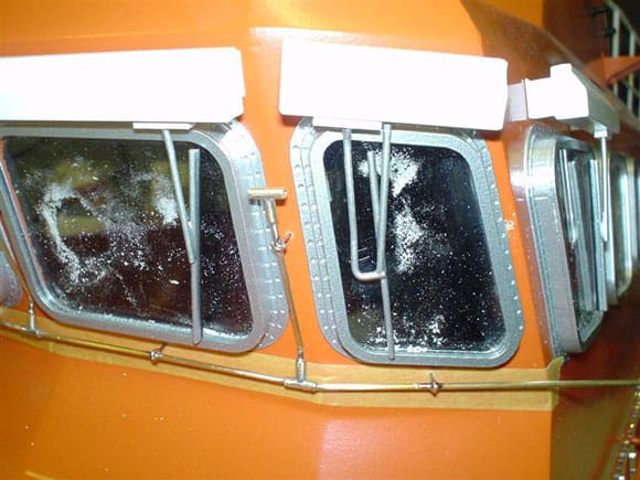
Perspex Window Set
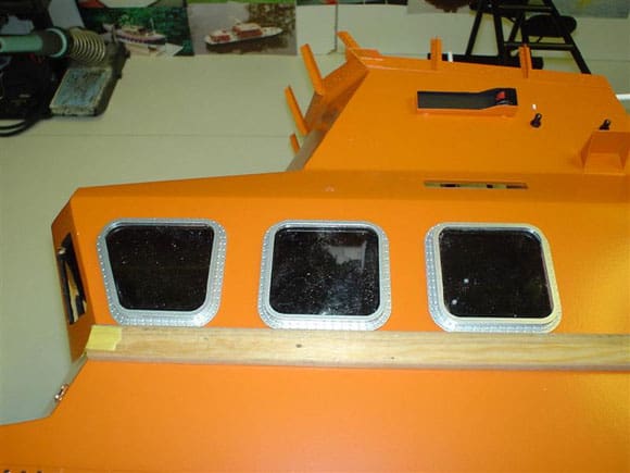
Windows and frames with all the relevant screw head detail and accuracy are supplied and in my opinion are the best I have seen available to date. Each window contains a total of five laser cut Perspex parts; the little detail of just showing the screw heads has an amazing effect on the finished model. It’s all made up from a set of frames. The frame itself is from firstly the outer flat frame, then a smaller inner frame, then the glazing frame and the last part is the inner mounting frame – so there is a lot to assemble and line up before final gluing. I have used Plastic Weld liquid glue for the frames, applied using a brush. The final window glazing is not fitted as this would be the very last thing to do. Painting all the frames was simply carried out by mounting them all on to a piece of cardboard with the use of double-sided tape. Tack stick each frame to it and that way all can be sprayed in one go. After a few days drying time I glued in the final glazing panels at the edges only to the inside of each frame with a special odourless cyanoacrylate superglue that does not cause blooming or staining. It is available from www.fivestardistribution.com. It does work although I found it slow in setting compared with normal superglues. As an added bonus Speedline can now produce Perspex window sets for most other lifeboats on request, depending on scale. See Photos 78 to 82.
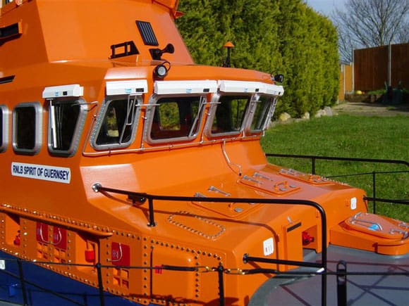
Wiper Boxes and Wipers
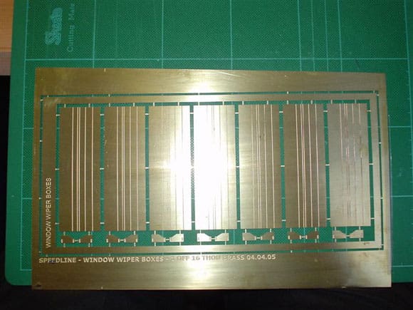
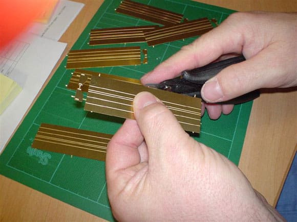
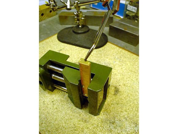
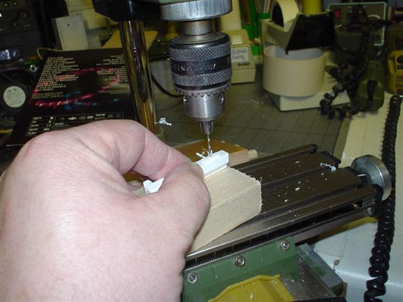
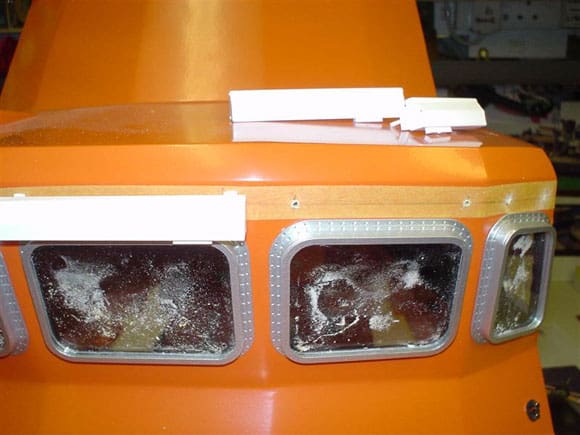
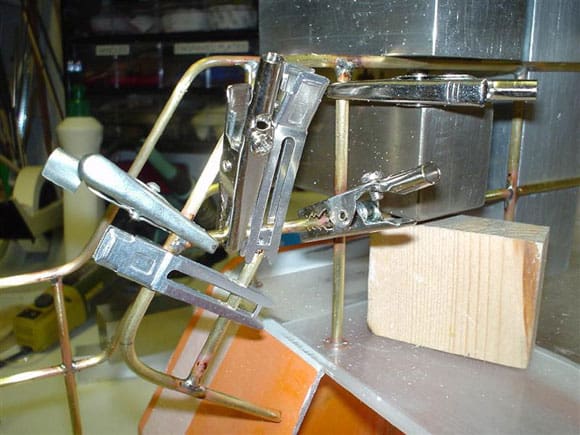
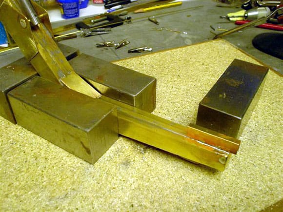
There are a total of seven wiper boxes which have to be made up and attached above the front and two side windows. The etched brass set contains the main boxes and end plates. The box sections have to be cut to length and folded on the fold lines. Certain folds can be done using a standard vice with plain jaws or using some flat bars of metal. Once the lengths of each box have been established I then cut them with a pair of sheet metal cutters and having removed the small retaining tags with a pair of fine side cutters, I filed and dressed them clean with fine wet and dry sandpaper.
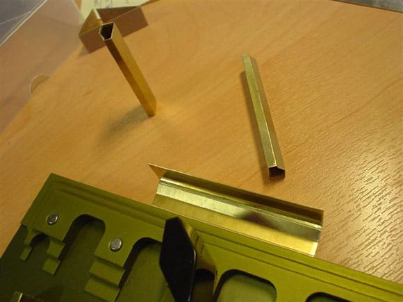
For folding small to medium etched brass I use Etch Mate from Mission Models (www.missionmodels.com) which has the advantage of holding the piece firmly on the fold line during the process. The best way I found to fold the wiper boxes was to start in the middle, one side at a time, and work outwards as far as I could and then move on to the next fold line. This starts each fold off cleanly. Then remove from the jig and complete the fold gently with a flat surface and a 5mm wide bar of metal. It sounds simple as long as the folds are all in the same inwards direction. In this case this is not so, as there is approximately a 40 degree angle going out and away, so thought and care was required. The end plates need to be offered up to confirm the correct end shape. The next tricky part is to solder along the join and solder on each end plate with the indented detail showing outwards.
On looking at the close-up photos, some other detail parts need to be made up from scratch. Each wiper box has two ‘U’ shaped stands or spacers at the back as mountings. A visit to my local model shop revealed, in the KS metal rack, an appropriate size of brass ‘U’ section, Stock No.182. This was cut to length and soldered on at the back. Note use of heat shunts to take away the heat from the already soldered areas. On a further thought, when it comes to attaching the wiper box to the model, just gluing it on did not seem strong enough, so I have drilled a hole in the centre of each ‘U’ section and inserted and soldered a brass pin which will eventually pass into a hole in the wheelhouse moulding. This gives a much better and stronger mounting.
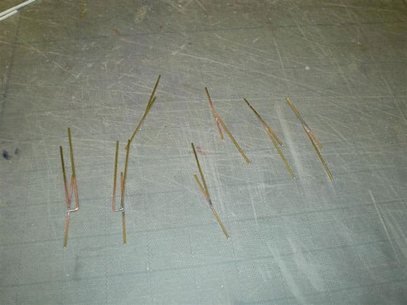
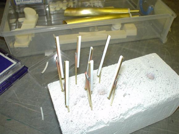
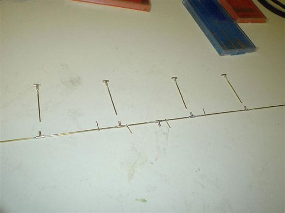
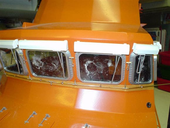
The windscreen wipers have all been made up using 1.5mm diameter brass rod, bent and soldered as per the photos except for the wiper rubber blade part and holder plate to the box that is glued-on plastic strip. The wiper assembly is attached to the box by means of drilling a hole slightly smaller than the rod and push fitting it into the hole with a slight amount of glue applied. The angle and placement of each wiper was as the full size Severn. See Photos 83 to 92.
Window Washer Pipework
On looking at the photos there is a noticeable amount of pipework serving all the front windows and on either side the first window. On the real Severn this is made with stainless pipe and these direct a powerful jet of water spray to clean each window. To recreate this I have used 1.5mm diameter brass rod bent to shape, following the contour of the front superstructure. To represent the ‘T’ joints I have used brass tube with an internal diameter to accept the rod. This was all soldered together using a fine tipped variable temperature electronic mains powered soldering iron. The whole pipe assembly is spaced off the real Severn with black pipe saddles which I have simulated with push in brass wire eyebolts from the Amati range of bits and pieces – also soldered in position. These were then highlighted with matt black paint after the whole assembly was sprayed silver. In my opinion this section can only accurately be made up on the model after the model has been painted and the windows glued in position – tricky but it worked for me. See Photos 93 to 96.
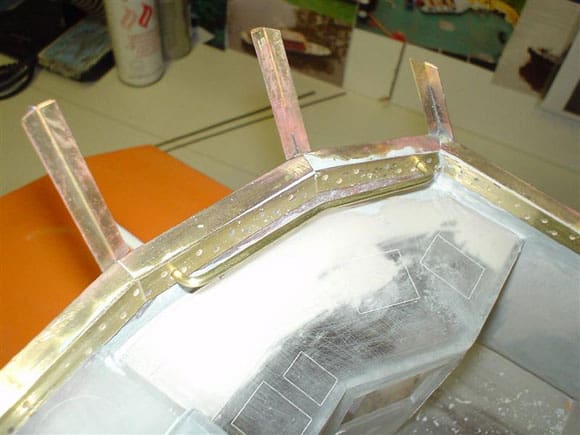
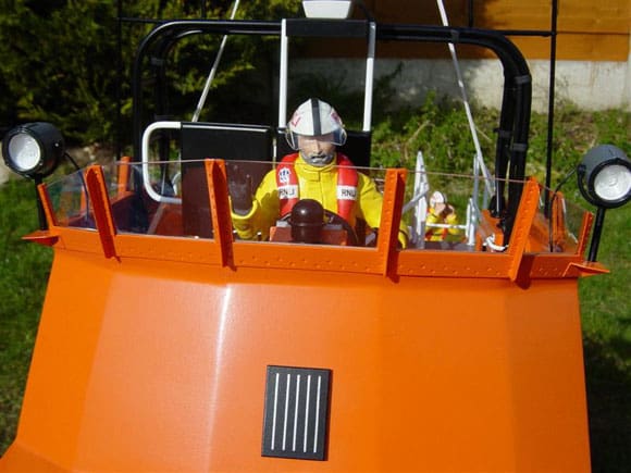
Flying Bridge Window Framework
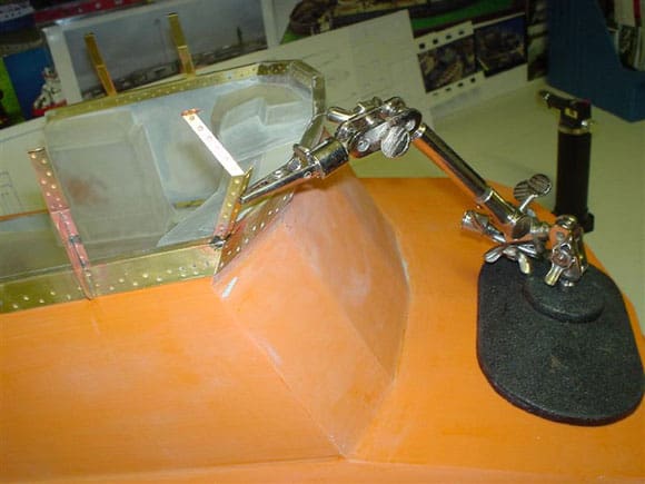
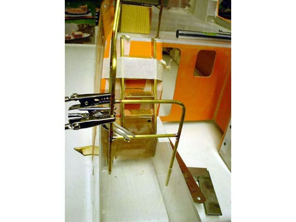
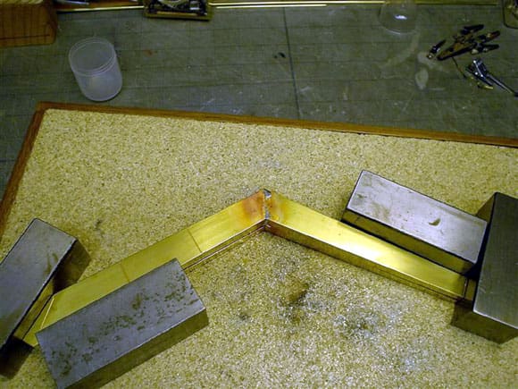
At first glance the various etched shapes to make up the entire flying bridge window frame looked very complex, with narrow strips requiring folds and curves. On closer investigation it is just made up of short straight lines; the base or ledge of it requiring bending to an ‘L’ section which then is placed over the top edge of the GRP and trimmed to length to suit the GRP (including the inner facing strips). The GRP does need to be the correct thickness so a little filing and sanding is required here and there for good fit. The actual folding of the ‘L’ section base was very easy due to it being of short straight sections. Once placed on the model it sort of falls into place and is simply glued on with Superglue. I decided to solder on all the uprights on the model which is fine as long the heat is not to intense and not for too long so as not to melt the GRP. Holding each upright with the use of a ‘no-hands’ tool was the best idea. Soldering takes practice I grant you, but gluing on such a fragile upright and expecting it to take the odd bang now and then is a bit of a non starter. The outer support on each upright was soldered on beforehand. Note the use of clamps to hold in place as well as to conduct any heat away. The uprights have been cleverly designed so that once the pre-cut Perspex windscreen is in place, the top section just needs gently bending over to hold all in place, which is a great idea as long as the paint does not crack as you bend it. It’s actually a highly detailed structure and very visible from all angles so great care should be taken to get it right. See Photos 97 to 104.
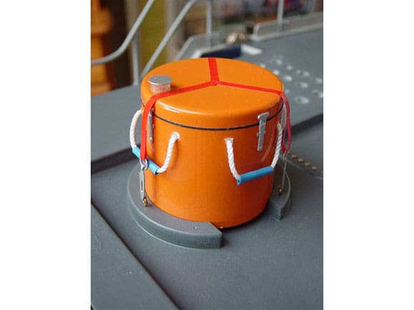
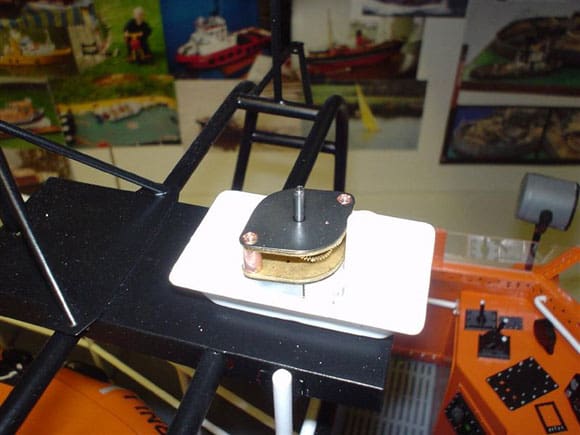
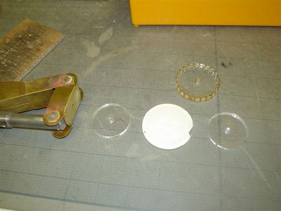
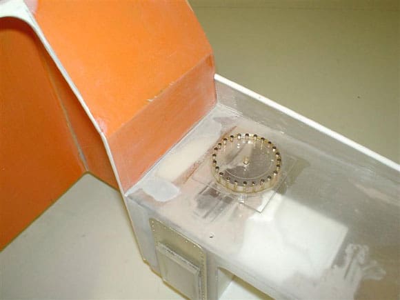
Water Pump Drum
Within a supplied Perspex mounting ring under the rear wheelhouse canopy, sits a large round container which in reality would contain a totally submersible water pump. This would have normally been supplied as part of the vac-forming set which for some reason I could not locate. I could phone and ask for a replacement or make one from scratch. I had two options: to either turn the item from a large piece of wood or find something of the required diameter and just by chance I found the plastic lid from small Humbrol aerosol can was a perfect shape to fit inside the Perspex laminated ring supplied. So it was just a matter of a fine sand all over, prime and spray orange. A length of black car lining tape was used to simulate the lid rim with blue tape for the straps. I glued on the supplied etch brass fittings along with hooks made up from 1mm brass rod – job done. See Photo 105.
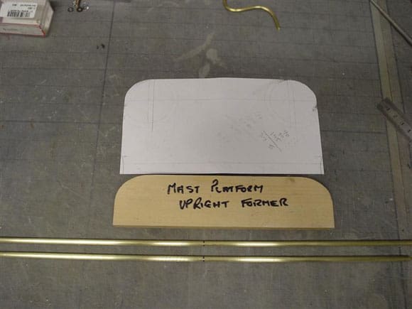
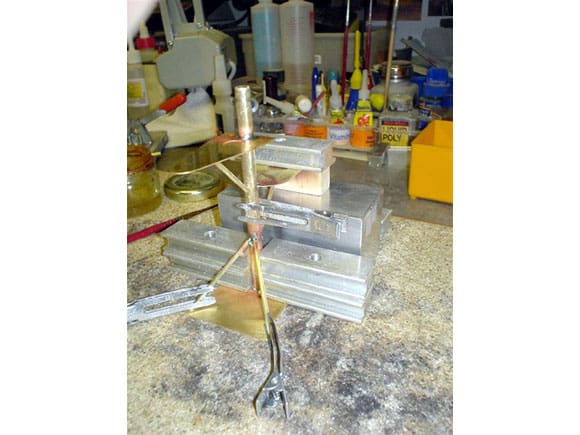
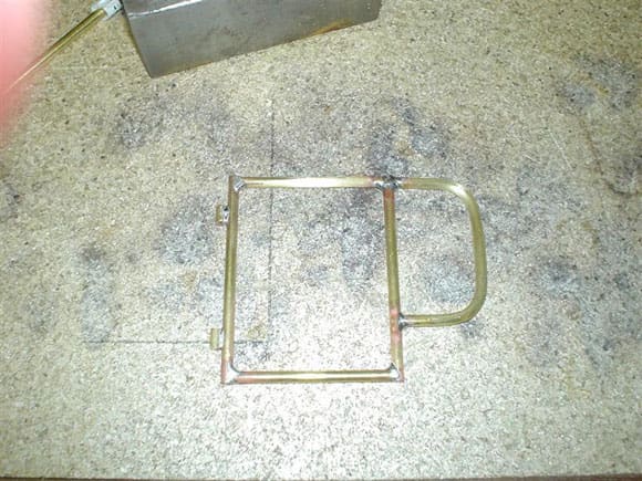
Roll Bar/Mast Platform
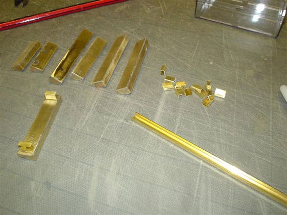
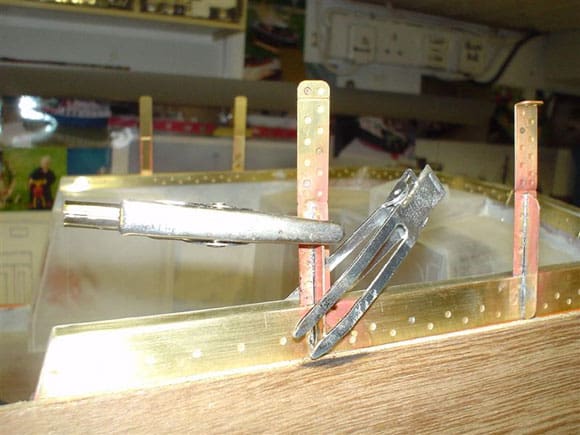
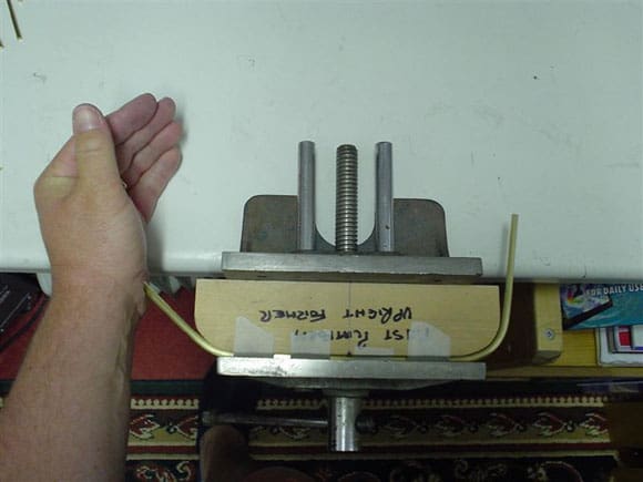
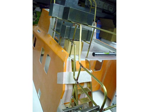
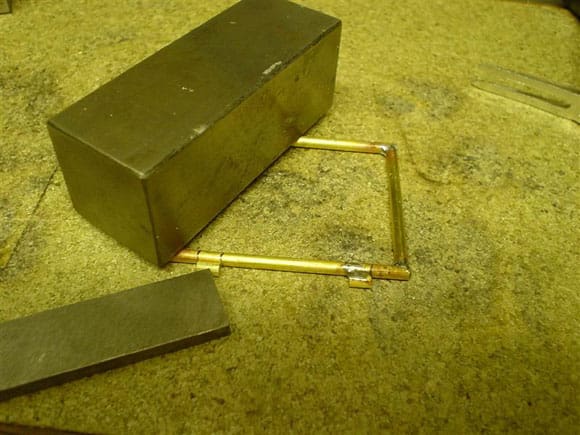
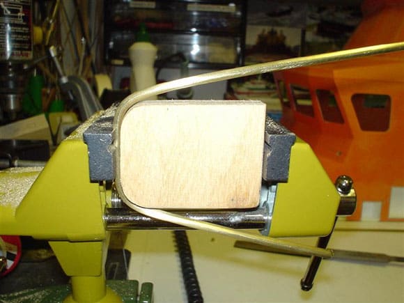
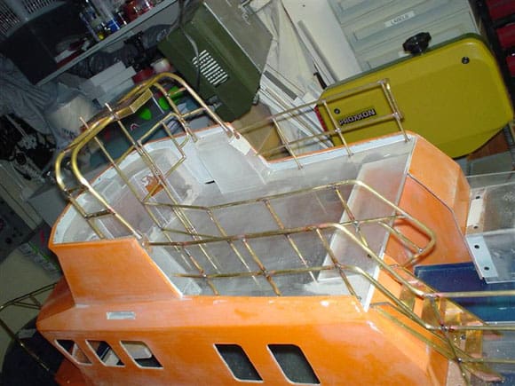
The roll bar as I call it, is made up from the supplied 5mm diameter brass rod and two are required. On looking at some side view photos, the rearmost one sits at an angle, although they are exactly the same shape. The only way I could bend them so that all four curves have the same radius in the same places was to use a wooden former held in the jaws of a vice. Bending was surprisingly easy, but once again you only get the one go at it so make sure it’s right. Measure and then measure again before bending. The height and angle required is set by the side boxes and can only be worked out by placing them on the model and cross referencing to the plan and photos.
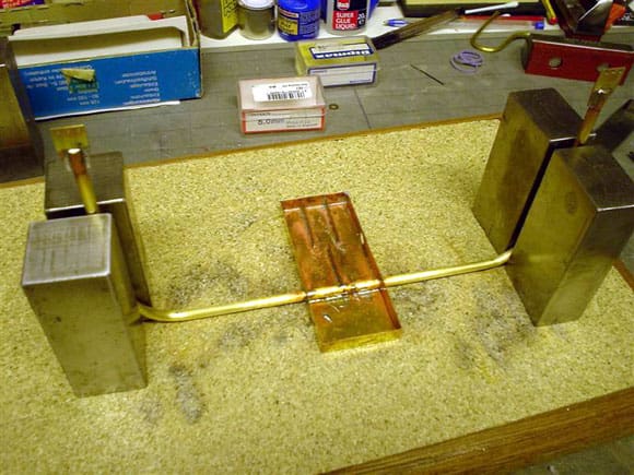
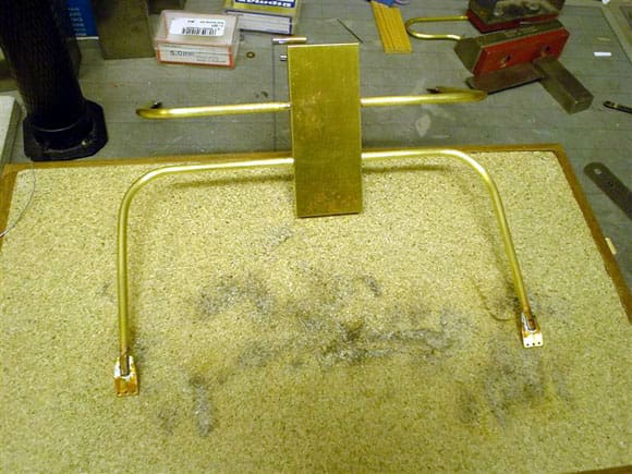
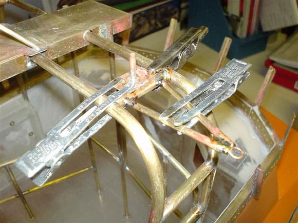
The radar and mast platform is made up from the brass etch rectangular base part which the roll bars actually pass through where the holes are – done after the bars have been bent and it can be a bit tricky to accomplish properly. A little modeller’s licence of a cut and join was required here and there to achieve the end result. All was then tack soldered in position until a perfect fit on the model, then permanently soldered. The rest of the mast platforms for lights, etc., are then soldered in place. Note the etched-in light mounting bases to indicate their correct position, which was also confirmed by the plan and photos. Other details such as strengthening braces, along with side aerial brackets, have all been made up from additional brass rod, tube, etc. Perspex mounting plates for the roll bar are supplied for the fixings to the Perspex side boxes. I decided to replace these by tracing the shape and cutting out from scrap brass etch material and drilling the holes. These were then soldered, one at the bottom of each roll bar, by means of a slot cut in with a hacksaw, allowing the completed structure to be bolted to the side boxes and making it all a stronger fixture.
Working lights can be installed as the main vertical mast is brass tube which is ideal for threading the wire inside. On this model all the lights are the supplied cast metal ones. I have made up other lights using clear acrylic rod cut and shaped in my lathe, then with the use of a light thin coat of paint to colour them. Also, drilling a hole in one end of each, half of the way in, gives the visual impression of a bulb fitted.
Mast and platforms were then all primed and sprayed satin black. Photos of the original show various cabling which I have reproduced by using the plastic insulation from standard black electrical cable bound to the roll bar with black trim tape. The various sockets have been made using small pieces of evergreen styrene tube cut and glued to a small square piece of flat styrene – simple but effective. See Photos 106 to 111.
Flying Bridge Railings
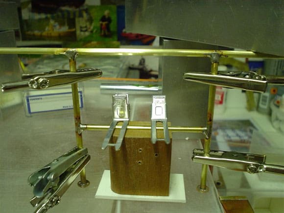
First job is to mark out their position. The same assembly format is followed for bending and soldering as per other railings. From the supplied 3.3mm diameter brass rod all uprights are cut to length allowing for at least 5mm to pass through the deck, then turned down to pass through the centre hole of the stanchion base or foot. To assist in a much neater stronger joint, again as per all other uprights, it pays to file a half round cup in the same direction as the handrail on the top of each upright. That way the handrail just sits on top of the now filed groove waiting to be soldered. The centre cross piece was measured for position and a wood spacer block cut out as a guide for the rest. Towards the control console there are two back rests with metal uprights which connect to the radar platform on the real one. On my model, for later easy painting, the rectangular frame work and gate will be totally separate from the roll bar and mast. Access to the ‘Y’ boat is via the nearside gate with hinges and gate catch, which I have cut and made up from brass rod and scrap bits.
The two back rests are just 3.5mm thick flat styrene cut to fit over the outside brass framework, rounded off at the edges all the way round then four support corner brackets in flat styrene are glued on the back of the backrest so that they appear to be part of the railing framework. These need to be finished in white and not black, so for painting I just masked the parts off before spraying the backrest black, removed the masking tape after the paint had dried and the correct colour white corner brackets are ready. Four hexagon nut heads were added, and each back rest was glued on to the framework with superglue gel. Life ring brackets are etched brass as are the hooks and all are simply soldered on. See Photos 112 to 123.
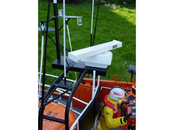
Radar
The outer casing is supplied as two vac-formings which need to be cut and trimmed to fit together. I have also added an internal strengthening frame made from styrene. I decided early on that I wanted the radar to rotate as per the real boat, and the best way to do it is to use a motor small enough to fit inside the vac-forming. Looking through the Robbe catalogue, part No.4124 gear-boxed motor was ideal for the purpose. It would rotate at around 26 revs per minute, and the wiring was concealed down inside the black linking cables strapped to the roll bar. The motor casing has securing bolts supplied, so I drilled tiny holes through the vac-forming and through the platform thus securing the whole assembly.
The radar arm is supplied as a resin casting, just requiring the two end caps to be made up from styrene and glued on. The centre spindle is just a short length of 1.5mm brass rod passing through the top vac-forming, and spaced off by a small nylon washer with the rod attached via a hole in the radar. All can then be pushed on to the spindle of the geared motor and held in by friction alone. To hold the top vac-forming to the lower vac-forming a nylon bolt and internal threaded spacer is used. See Photos 124 and 125.
H Section Aerial
This is fitted to the very top of the mast platform and has been made up as follows. Each aerial section, ‘T’ shaped, is just soldered together pieces of 1.5mm brass rod. The square block in the centre is a square piece of brass drilled through on each flat side in the centre – the diameter of the holes should be the same as the rod diameter. The upright is a length of brass tube to fit inside the mast tube, all soldered and at 90 degrees to the aerial block. In the past on other small scale models, I have used the brass flat pins as found in mains plugs for rectangular and square materials. As a side note, mains plug brass pins make very good rudder tiller arms.
Internal Detail
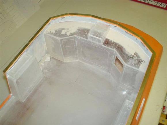
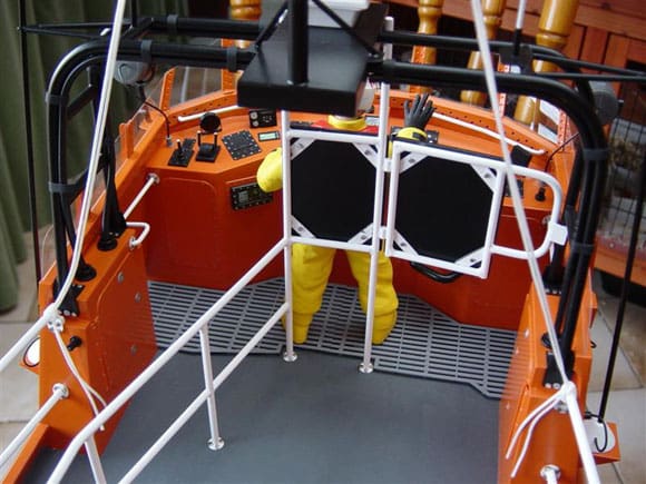
Internal detail is carried out at the modeller’s discretion, the layout of which can be obtained from the plan, and some internal photos are on the CD, although few and far between, so further investigations would need to be carried out. The web can be a very useful tool for this, or better still a visit to the lifeboat in question. I decided, due to the size and scale of the windows, that internal detail should be carried out. The best time to start is before fitting the flying bridge roof/floor. That way easy access can be gained for sizing and positioning.
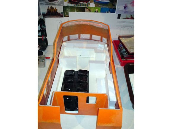
As you can see from the photos I have built up an inner floor, side cover boxes and a control console. The seats are from Speedline, available as an extra set of vac-form mouldings which just need to be cut, glued and trimmed. The base boxes need to be made from scratch, all from styrene as are the inner wall, stretcher seat, engine room hatch/companion way, screens, etc. Everything needs to be well attached to the floor and be ‘insertable’ as a complete structure from underneath once complete.
A wealth of detail can be added which I will be doing as a long term on and off project. Speedline also produce a seated figure which will be ideal sitting inside looking out. See Photos 126 to 130.
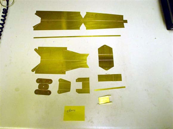
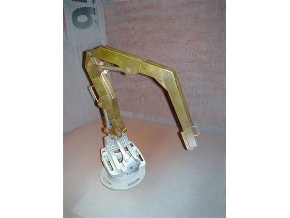
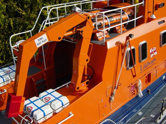
Hiab Crane
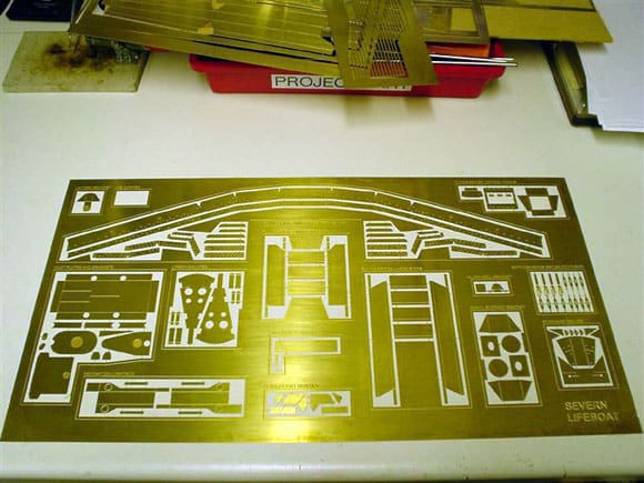
A major item and feature of the Severn’s equipment list is the Hiab crane which Speedline have gone to great lengths to recreate. Once made it is very strong and forms a good basis for a working model. Its use is to lift the ‘Y’ boat on and off the Severn as and when needed. This comes as a major part of the detail set, all assembled from the brass etched sheet except for the hydraulic rams which have been cast from a material called Myzak, which I am told by Speedline is what Dinky toys are made from.
The round discs that make up the slew ring are Perspex, as are hook and cover components. As the Hiab is a major feature of the model I decided to build this very early on. Like most modellers I find there is always something special on a model that draws your eye to it, and this is one of those. I also decided to construct this early on in the build as it would be a good learning curve to get a feel for manipulation and bending large brass etch pieces. It must be said that brass etch components have sharp edges so care is required. It pays to separate all the components required for the Hiab and place them all out in front of you at the same time, forming a picture in your mind on how and where all the folded parts locate.
Next task is to clean up and dress the edges of each component part to remove the small holding tags which secure them to the carrying frame – but not too much filing otherwise you will start to lose the crispness of the part. Folding on the line of some parts could only be done with the use of a vice or flat surface. The photo CD provided close up detail to show where certain items fitted over the main body of the crane.
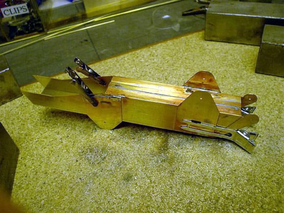
Deciding how you want the final displayed position of the Hiab on the boat needs a little thought. At sea they would normally be parked as on my model; alternatively you could have a figure standing near the controls and the Hiab arm slightly stretched out ready to lift the ‘Y’ boat lifting straps.
Soldering presented no problems whatsoever. Once complete it certainly looked convincingly real, very much a model in its own right. It would be nice to see it working and I am sure some clever thinking modeller out there will motorise it and tell us how they did it. The truck modellers with miniature hydraulic sets already do similar things in Germany and Holland – the downside is that hydraulics can be very expensive. See Photos 131 to 138.
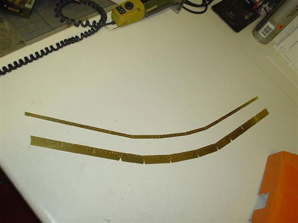
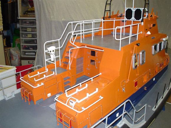
Bow Railings
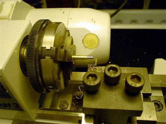
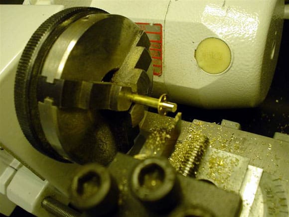
Marking out the eventual position and shape of the rail is very important. For bending the large bow curve at the correct diameter I used a piece of small drain pipe as a former. To make the bow railing I found it much easier to start in the middle at the front and work symmetrically back. Each upright requires a five-hole round mounting boss soldered on from the etch brass detail set. My concern was the secure fitting of the final rail assembly. The problem was I would have liked to drill out the centre hole of each mounting boss the same diameter as the rod. That way I could pass the 3mm upright through it, allowing a little over length to pass through the deck to the inside of the hull for fixing. This gives a stronger and more positive fix. Unfortunately as the brass material of the foot was thin it would not have been a wise decision to drill it out. A further alternative was to file it out. As I had a small lathe I decided to turn down the ends of each upright thus reducing its diameter to fit the existing centre boss hole, and as they say – job done. Soldering the feet on had to be done off the model – the rest was completed on the model hence a great use of metal blocks and clips. The model makes a great template! See Photos 139 to 145.
Stern Railings
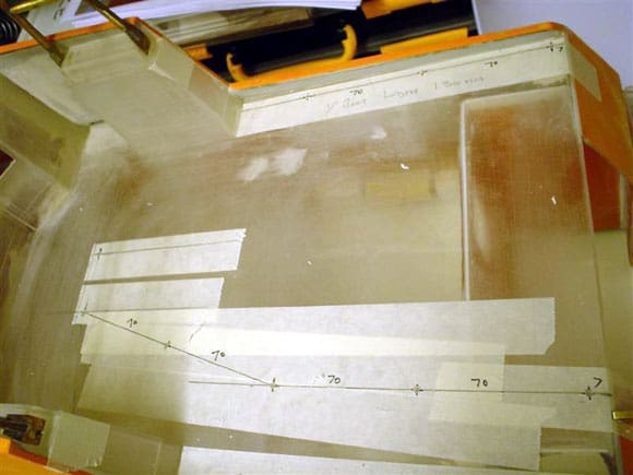
This area of construction was most difficult and time consuming. The design of the stern rail by the RNLI has had a few changes and so far I have found four variants, so if you want to get it right, visit the real boat you are to base your model on.
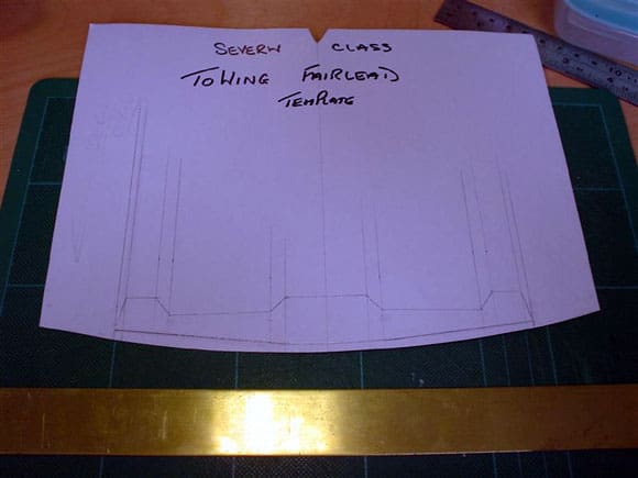
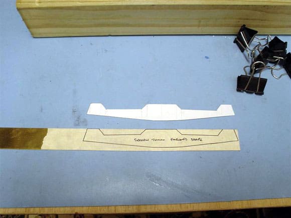
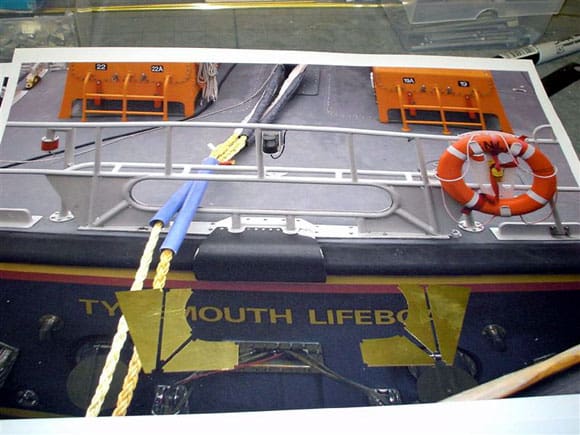
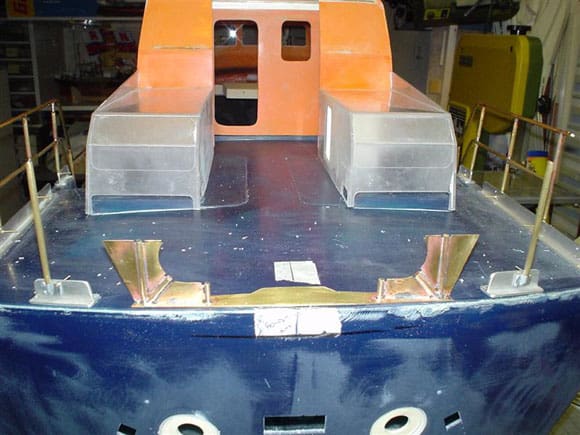
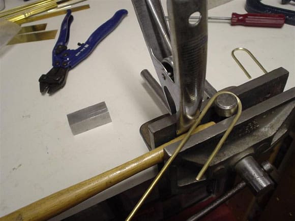
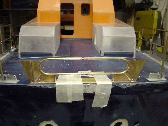
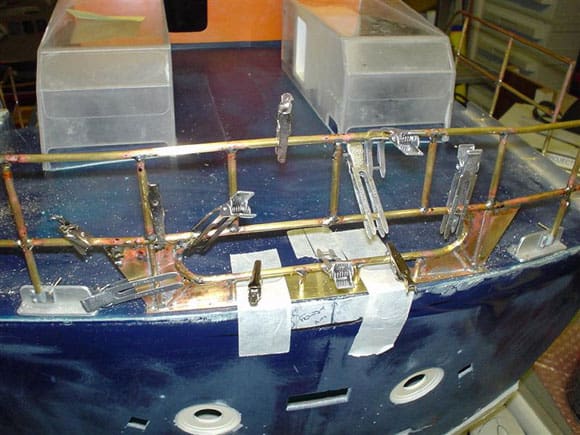
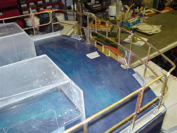
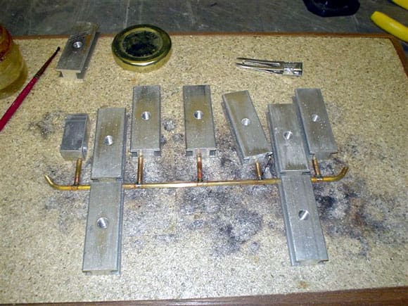

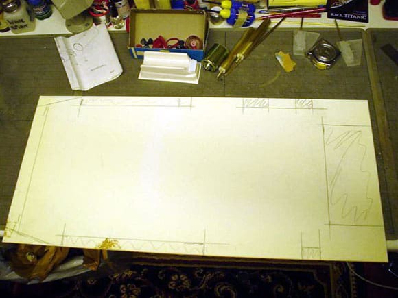
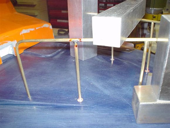
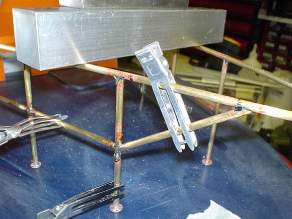
To start anything like this you have to find the key component. The stern rail has a base plate and in the centre is the towing fairlead, and as everything seems to sprout up and away from it, where better to start. The drawing does not give an overall face view of the stern railings so the only way one can work it all out is from the sizes of the etched parts and the photos to see how it all comes together. It would have been a huge help if the base plate was part of the brass etch set but it wasn’t. The plan shows a bird’s eye view looking down on the deck which gives me the shape of the base plate, which then just needed scaling up to the required size, and making sure that all the etched parts, rod, etc., will fit on it and look correct. I made up a base plate template in card. Once happy that the shape was correct and that all parts could fit it, I transferred it to a piece of brass sheet 1mm thick, luckily from one of the etched brass mother sheet scrap pieces and cut it out using a band saw. With that made I could then mark out and drill the required mounting holes. Once fitted to the deck temporarily, I could then accurately assemble and solder the railings in position on the model, my usual method. GRP can withstand some heat, but not a flame directly applied, so care has to be taken.
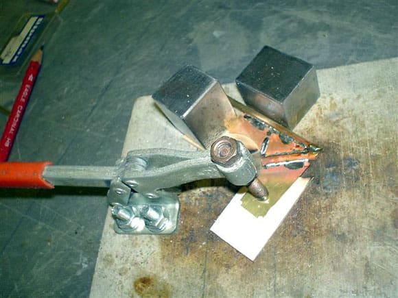
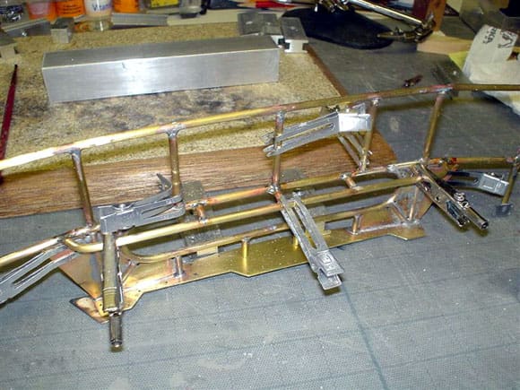
The gob or centre loop is made from brass rod and has to be bent into a tight radius. Once again a former was required and as luck would have it one end of my hammer was exactly the former I needed, so once clamped into a vice I could then bend the rod around it, which does need a bit of doing. It is possible to soften the brass rod by heating it up with the blow lamp and allowing it to cool. The two loops were produced, cut and trimmed to fit inside the etched panels and then soldered. Any gaps between plates and rod can be filled with solder and made good. When making up the uprights, note that the top handrail is curved similar to the deck camber, so I had to allow for three curves on some pieces. It pays to do all the uprights, then the centre cross pieces and last of all the top rail.
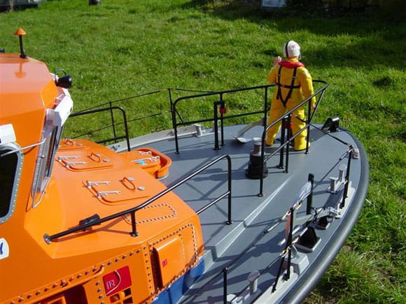
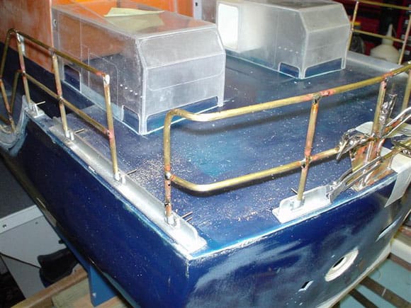
Please note that although Speedline supplied in their older kits including this one, pre-cast Myzak stanchions for the those at the rear, I have chosen to use the base plate part and 10mm of the upright only. The main upright is brass tube of the same inside diameter as the outside diameter of the Myzak stanchion. That way from base plate upwards it is now brass, making life so much easier for soldering a complete one-piece railing assembly. I am informed that the stanchions have caused some headaches, so Speedline have now changed these for complete brass versions and I do have some which I will change to as and when time allows – they are a better quality item. The rear side handrails follow the same format. Once again time needs to be taken on bending and forming the brass so that you get the right sweeping down curve to the next deck level on both sides. They do also sweep out slightly.
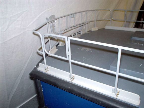
There is an access gate on each side which I have made separately and soldered in as though hinged like the real ones. Speedline does state that it is possible to glue each stanchion base plate to the kickboard, but in my opinion this would not be strong enough as they are bound to be knocked. So I, like a few other builders of this kit, decided to obtain some 14BA brass nuts and bolts from Squires Model and Craft Tools, Tel: 01243 842424. The bolts are cheese-head, pack of 100 Part No.CH14100 and a pack of 100 brass hex nuts Part No.BN14100.
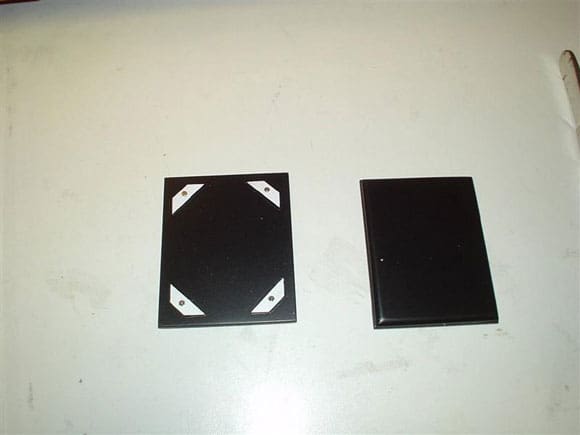
The stanchion bases consist of two types, triangular and rectangular. All have a mirror image backing plate that needs gluing in place on the inside of the kickboards. I hope the photos will explain this a bit better. Each plate has the hex nut heads crisply cast on which I needed to modify for my method of fixing to the kick plate. This is done by filing down two hex heads on the stanchion face rectangular plate and one head on the triangular stanchion plate. Drill a hole where the centre of the hex head was for the brass bolt to pass through. This is then offered up in position on the kicking board for the hole to be marked and drilled. The bolt is passed through the kicking board and the stanchion base so that the brass hex nut now replaces where the cast hex nut would have been. Tighten up to achieve a more secure stanchion and still have the nut head showing once the bolt excess has been cut down and paint grey. Hopefully this makes sense! Now the rear plate requires a hole drilled the diameter and depth of the bolt head, in the same location as the bolt head so that the plate fits over and hides the bolt’s cheese head. This is glued in position with superglue gel.
The thin black cable going through each stanchion on the sides of the lifeboat can be represented in a number of ways including brass rod, actual twisted steel wire of the correct diameter, or brake caliper wire as used on bicycles and painted black. I actually used round black hat elastic which can be purchased from any good needlework shop. All craft shops are well worth a visit, including Doll’s House shops. Anyway, the elastic should be lightly tensioned. The tensioners are made up from 1.5mm brass rod. At each end of the elastic I have threaded a 13mm length of black heat shrink sleeving, then the elastic end passes through the eye of the tensioner which is 1mm brass wire bent to shape using round head pliers. The elastic is then passed back through the sleeving and by applying a little heat on and along the length of the sleeving with the tip of a soldering iron, the sleeving will be shrunk and this will hold the elastic in position under gently tension. Cut off any excess leaving at least 2mm hanging out for adjusting any slack over a time period. Not totally correct but from a distance it works. See Photos 146 to 159.
Fittings
Speedline have supplied many of the major and minor fittings and they are very good quality, made from either Myzak, Perspex, or brass etchings. There are a few that need to be made up from scratch with whatever comes to hand. The only Myzak fittings I found to be over-size were the vents, especially where two of them need to be fitted next to each other inside the vent boxes. These could have been remade, but as I was coming to the end of a very long build I decided just to fit one where two should be instead and will correct it later as time allows. One major fitting not supplied is the helmsman’s steering wheel, but as luck would have it The Model Slipway produce white metal 1:12 scale lifeboat fittings, so I have purchased two as one is also needed inside the cabin. The other appropriate additional fitting are a couple of fire extinguishers. The Speedline fittings that do stand out well once painted, are the valves, fairleads and anchors. The lifebelt rings are cast resin and need very little work to prepare for painting. The horn and loudspeaker are Graupner fittings. The small solar panel at the front is made up from styrene, sprayed satin black and with the fine silver lines cut from car lining tape. See Photos 160 to 170.

