Sealight
ALLAN MILLER builds the Mountfleet Models kit
Enjoy more Model Boats Magazine reading.
Click here to subscribe & save.
This model has been around for sometime, but it remains popular because it builds into a nice practical size of model and there is plenty of scope to individually detail it and of course it can be either electric or steam powered, the later though requiring some ingenuity to get everything into the after part of the model. Length is 32 inches, beam is 8 inches and the scale is 1:32. Current UK price is £299 and it is only available direct from the manufacturer who regularly advertises in this magazine. I was therefore looking forward to building it because it makes into a detailed model without too much extra work and there is plenty of access to the hull interior in which to fit the batteries, motor and radio gear.
What's in the box?
This is a complete kit, but does not include (as is normal), the glues, paints, motor, batteries and r/c gear. For your money you get:
A GRP moulded hull, engine room casing and ship's boat, Photo 1.
Over 600 white metal fittings, Photo 2.
All necessary wood for the decks and coamings, Photo 3.
Stripwood, cordage, wire, propshaft, propeller, full size drawing and instruction book, Photo 4.
Getting started
Having checked the contents in the kit box I started first by washing in warm soapy water the three GRP mouldings. These were left to dry whilst I studied the suggested construction sequence. Having read and absorbed this, I decided to add three extra features to the model and these were a smoke unit, working navigation lights and a sound unit. Once I had decided roughly how best to install these units, work commenced. Let me say now, this is not a difficult kit to build and because the hull is of a 'tubby' shape, weight is not a problem.
The hull
First task was to drill a hole and then open it out to the correct size in the moulded boss on the hull to take the propshaft tube and then the stern frame along with the rudder was fixed in place, Photo 5. Two part epoxy glue was used to hold this in place and while it was curing I kept checking that there was no movement restriction for the rudder. A supporting block for the propshaft tube inside the hull was also glued in place.
The motor is direct drive and is just held with elastic bands and a blob of bathroom silicone sealant to a moulded plastic motor mount. This moulding will need a support underneath it to attain the right height for proper alignment. After dry-fitting the motor, its mount and coupling to the propshaft and making sure it was nicely aligned, the motor mount was glued in place. The motor and coupling were as recommended and purchased from Mountfleet Models. All the running gear was then removed as far as possible, pending final installation later after the dust had settled as work continued on the hull!
Using a small drum sander attached to an electric drill the inside top face of the hull was smoothed and filled, then sanded again to be as good as it could be, after which the deck edge stringers were fitted,. For this, plastic (styrene) strips are supplied in the kit for the forward section, Photo 6, and wood for the aft part of the hull, Photo 7. The styrene stringers are in two layers to aid taking the hull side curve and after marking their positions on the interior of the hull the first layer was fixed in place using thick superglue. After clamping the second layer in-situ over the first, these strips were then secured using liquid polystyrene cement (Poly Weld or equivalent). The deck edge stringers in the after part are of wood and need to be cut to take the deck edge curve at the stern. The positions of the deck crossbeams were marked as per the plan and the beams themselves cut and fixed in place using epoxy glue. The wood for these is supplied in the kit. Once dry, a fillet of car body filler was introduced to the underside of all the stringers and the cross beam side joints to strengthen them. Car body filler was also added around the motor mount, the propshaft tube to hull joint, the rudder post through the hull and around the stern frame mounting lugs.
Decks
The plywood sub-decks are precut and were removed from the carrier sheet and trimmed to fit the hull. There is not much adjustment required and when happy with the fit, they were glued in place over the stringers and cross beams with epoxy glue, Photo 8, and please note the wash port openings in the hull. Hatch edge coamings came from the supplied plywood and using a relatively fast drying PVA glue, were fixed in place, Photo 9. From the same sheet of plywood, there was enough surplus to make a hull interior baseplate to which would be mounted the batteries and some of the radio equipment. There are some white metal fittings which are glued directly to the hull exterior (see Photo 9 again) and it is best to do this before painting the hull. There are 14 separate bags of fittings and each is marked and relates to a part of the model's construction and this does this makes the project much easier.
Basic main hatch, bulwarks and hull painting
Following the step by step instructions, the basin 'shoe box lid' style of the main hatch cover was completed with no problems, Photo 10. A reasonable fit was achieved over its coaming and after adding all the relevant white metal fittings, it was ready for painting. It is quite nice to stain the top of the hatch, but it might be worth testing the stain on scrap wood to ensure you get just the right shade. All the bulwark supports were then cut to size, but not fitted until after being painted.
After adding the capping rails, the hull was ready for painting. I tend to paint as I build if possible and two coats of red oxide primer were spray applied to all areas of the hull. The waterline was marked and then masked off and satin black applied to the above the waterline section of the hull, Photo 11. The insides of the bulwarks were painted brown ( a special mixture as described in the instructions) and the supports then added, having been painted earlier.
Winch
One of the great pleasures with this type of kit, is that you can spend time doing something different whilst the paint is drying. So, all the fittings that are attached to this forward part of the deck, including the winch, were made ready and painted. These fittings are of white metal and will need some slight cleaning and fettling, but on the whole are well cast and in any case, a deficient part will be promptly replaced by Mountfleet Models. The winch itself was painted in its individual components, Photo 12, before being assembled after a 'dry-run'. It was then 'dry-brushed' with a gunmetal Humbrol colour to make it look more realistic, Photo 13. Cordage for the drum is supplied and the whole thing was over-sprayed with matt varnish and put to one side.
Mast and boom
These were next to be assembled. Once again, all the white metal fittings for these are altogether in one bag. Wood dowelling for the mast and boom is supplied, but will need shaping. It is not a bad idea to leave an extra length on the bottom of the mast piece to hold it and to enable it to pass through the deck and be securely mounted. All the fittings relating to the mast and boom were painted separately before being assembled on to the dowels, the correct positions for the fittings being clearly indicated on the full-size plan. When both mast and boom were complete, they were given two coats of matt varnish and left to thoroughly dry, Photo 14.
Finishing the main hatch
The main hatch cover was next to be properly fitted out. Only the sides were primed and painted brown and dummy planks in the top were stained. Material to simulate the canvas sheet cover is supplied and this was cut to size and glued in place. Then the securing blocks around the hatch edges were added and lifting rings to the dummy planks. The small tender/lifeboat is a little model in its own right. If you don't want to detail the interior, then it can be stowed upside down, which is a matter of personal choice. There is nothing difficult with this small model and the instructions are clear enough. The boarding ladder and oars were painted before being secured together with the boat to the top of the hatch cover, Photo 15. All cordage required is in the kit and a piece of beeswax supplied means that running the cord through it removes the hairy look. A medium shade of wood dye will also help make the cord look more realistic.
Bow deck overlay
The kit includes a printed 'planked' plywood overlay for the forward section of the main deck. This was trimmed to fit and glued in place after being given a wash of well thinned black oil paint, which stained the deck overlay very nicely. Photo 16 shows how this looks with all the fittings in place.
After deck area
The white metal stanchions around the edge of this deck will need to be correctly positioned, the rails added after bending to shape, and the joints then glued. The stanchions are not intended to be bent, as white metal is quite fragile, so care is needed. The stanchions were NOT glued to the deck at this stage. Once assembled and the rails glued to the stanchions, the whole stanchion/railing unit was removed from the model and painted white, ready for re-installation and final fixing as in Photo 17.
Superstructure
Wheelhouse
This is assembled from printed plywood sheet parts, Photo 18. On the front, back and sides are marked the positions to scribe in the planking detail. This is best done whilst the pieces are in their carrier sheet and before cutting away the window openings. These will need to be carefully cut out, but the instructions are clear on how best to proceed. The front locker was then added and the unit was ready for painting. Once again all the fittings, both inside and out, were painted separately before fixing in place before a final overall coat of matt varnish Glazing is straightforward enough, but try to avoid getting glue blobs on the clear plastic! The wheelhouse was then ready to be glued to the superstructure base unit, Photo 19.
Engine room casing and funnel
The base unit is a GRP moulding and to this are added white metal fittings to give it detail. Photo 20. The instruction book and the full-size plan help you through this task and the only personal planning required is whether to add fittings, before or after painting. Once complete and after masking off the wheelhouse attachment area, this GRP unit was sprayed with red primer and then the sides painted brown. There are numerous detail parts to be added including of course the funnel.
The main body of the funnel is a length of plastic tubing and near to the top of the inside of the funnel, a plastic disc with a hole in its centre was glued to accept the smoke unit outlet pipe.
Small holes, as required, were also drilled through the superstructure to enable wiring from both grain of wheat bulbs to pass to the interior of the superstructure and the bulbs themselves were placed just behind the light frames.
Completing after deck area
The remainder of the engine room casing fittings include vents and a water tank, which are best constructed, painted and then fitted later. The final job was to install the rudder chains and their channels to simulate the steering mechanism and once again, each part was painted before being fixed in place.
As mentioned earlier, the brown is actually a mixture of colours, the proportions of which are clearly explained in the instruction book. With the painting complete the remainder of the fittings were added before a couple of coats of matt varnish were applied, Photo 21.
Rigging and crew
Plenty of cord is supplied for rigging and for this, patience is a virtue, but it is just a matter of persevering. There are no ratlines on my model, but I have seen some models so equipped, which again is a matter of a choice. The three crew members should be painted as appropriate and placed in 'crew-like' positions.
Batteries and radio control
Simple! A two channel r/c system is all that was needed for rudder and motor control as the extra electronic fittings would be manually controlled. After painting was complete, the rudder servo, motor, coupling and propshaft were re-installed. The drive battery sits under the main forward hatch and two switches, one for power to the speed controller and the other for the receiver supply were positioned, for ease of access, inside the rear of the main hatch coaming, Photo 22. A 15 Amp electronic speed controller (ESC) and a six volt sealed lead acid (SLA) battery were more than enough for this model and were wired up and tested. The smoke unit and navigation lights are wired separately via manual On/Off switches to a battery box containing four AA batteries, inside the engine room casing, Photo 23.
Underneath, within the stern access area is the rudder servo and just forward of this is a Model Sound unit which produces both a steam and horn noise, and in some volume it has to be said, Photo 24. The unit works by having a micro-sim card installed in a can about the size of a 70ml paint tin. It works on its own and is not linked to motor speed and a full charge will give about three hours of sound. Nevertheless, it is loud and effective and to change engine/ship noises, one only has to change the mini-sim card. The whole unit can be easily moved from model to model. So, a balsawood box was constructed which is removable and the sound unit sits in this and to let more noise escape, the glazing is eliminated from the portholes around the superstructure. Ideally it would use the hollow funnel as a resonance tube, but you can't easily have smoke and sound from the same orifice!
Ballast and sailing trials
It took a lot more lead than anticipated to ballast down to an acceptable waterline, so some was made removable to enable easier transport to the water's edge.
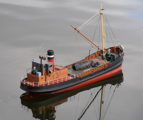
On the water, the model sails well, but it is not too good at reversing in a straight line which is not unusual for a single screw model. Being able to carry a huge battery capacity, means that this is a great model for those long sailing sessions on pleasant summer warm afternoons, Photo 25.
Conclusion
This kit builds into a well detailed model which looks the part both on and off the water. There is nothing particularly difficult in its construction and it has enormous scope for weathering and super-detailing. Recommended!
Mountfleet Models are at: Rock House, Bankwood Road, Womersley, Doncaster, DN6 9AX, tel: 01977 620386, website: www.mountfleetmodels.co.uk

