When I started to build radio controlled model boats some number of years ago my hulls were all scratch built for a number of reasons:
1. My models were mainly built from plans for which a commercial, (fibreglass), hull was not available.
2. I enjoyed working with my hands, and I also enjoyed working with wood.
Enjoy more Model Boats Magazine reading.
Click here to subscribe & save.
3. Fibreglass hulls cost many times more than the cost of a scratch built hull using my construction methods.
I must admit however that my last model that featured in a series of articles in Model Boats was an Arun lifeboat using a Metcalf Mouldings hull!
The last model that I completed was HMS Peacock, and you may have read about the bow thruster system that was installed in her in a previous Model Boats article.
The last article on a scratch built hull for a scale model was published, according to my records, in June 1998, apart from the fairly basic free plan features. There must be some readers of Model Boats out there who want to scratch build a hull for a model but have never done so, because they are unsure how to go about it. It is for these modellers that this article is intended.
Intention
In this first part I will describe the construction of the hull and the adhesives used in some detail. Most scratch built hulls that I see in clubs around my area are moulded in fibreglass. Using this method involves making a wooden plug, the finish on which has to be of a high standard because a mould has to be made from it, any imperfections being passed on to the finished hull. I can see the point of this if a number of hulls are to be produced, but for one hull it involves, in my opinion, a great deal of unnecessary labour. It also involves using fibreglass and resin that is both flammable and toxic, requiring a well ventilated workplace, apart from being quite messy to work with.
My hulls are constructed using cheap 4mm plywood for the frames, keel and deck and balsa for the planks. The plywood used doesn’t have to be of high quality such as marine ply as it will be covered with fibreglass resin and therefore not exposed to water damage. Indeed the plywood used in this article was salvaged from the back of an old wardrobe!
The planking on the model is done using 1/8in balsa which doesn’t have to be carefully done, as it is merely a support for the fibreglass resin and matting with which the hull is covered when the planking is complete. This produces a strong lightweight hull which, if damaged, is easily repaired.
Adhesives
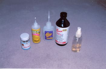
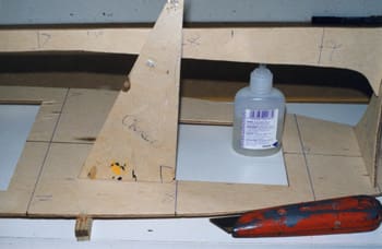
Before starting to describe the build, a few words about the adhesives that I use. These are cyanoacrylate esters, (Superglues), that are either Grip or Pacer make. I also use an accelerator spray called Pacer Zip Kicker, Photo 1. These glues come in different types, i.e., thin, medium and thick, which I use depending on the part of the model where I am working and the material I am using. Superglues bond almost immediately which can sometimes be a problem. Pacer market a glue called SloZap that takes up to about a minute to cure, depending on the temperature where it is being used, allowing some adjustment to the part being fitted. I you want to speed up the curing process you apply a light spray of Kicker and the glue will grip almost immediately. If you haven’t used cyano glues you will not be aware of the problems associated with their use. These glues must be used with a degree of caution.
Superglues aren’t new so we are all well aware that if you get it on your fingers they will stick together, and in freeing them you will remove some skin. If however you use Kicker with the glue, the combination produces a great deal of heat, which if it lands on your skin will give you a most painful chemical burn. I always wear disposable surgical gloves when working with cyano, and I also use an after work cream. Finally the glues should be used in a well ventilated place and you should avoid inhaling their vapours. Read the instructions and warnings on their containers. Pacer also produces a debonder to free bonded surfaces which is very handy to have around.
Building Plans
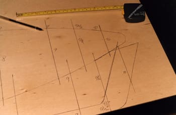
Before building commences I would recommend that some time be taken to carefully study the plans. As I am not very careful when handling my plans the first thing I do is to make several copies of them, at A3 size, at my local garage or Post Office.
Most new plans are now drawn to a scale of 1:50, although plans drawn some time ago will be to a scale of 1:48. If you wish to convert plans drawn at 1:50 to 1:48 they should be copied to 107% of their original size. However the difference in scale is so little that it doesn’t really matter. I make two copies of each part of the plans and stick them together with transparent tape, one copy for reference while working on the model, and one for templates.
Building Commences
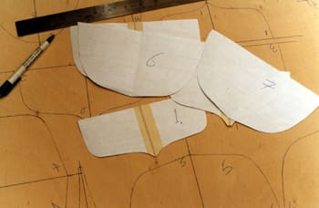
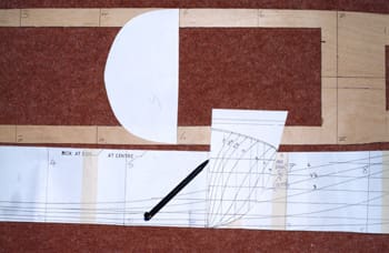
The first task is to cut out the templates for the frames and transfer the outlines onto the 4mm plywood, Photo 2. Next draw, on the inner side of the frames, the part that will be cut out and discarded, Photo 3. If you are careful when drawing the frames onto the plywood you can save a considerable amount. The distance between the inner and outer edges of the frames should be about 5/8in. At the bottom of each frame, where it will be notched out to join the keel, measure upwards about 1in and draw a line across the bottom of the frame. This will ensure that the frame has sufficient strength to prevent it from splitting while you are working with it.
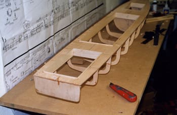
Remember to number the frames in several places! Because I was installing an untried bow thruster system in the model I used frame 7 as a watertight bulkhead, as you can see in Photo 4. When all the frames are cut out sand the frame edges and lay them aside until required.
Keel and Deck
Cut out the keel template, to which the frames will be attached, about 1in wide. See Photo 5 and subsequent photos for details. Attach it to the plywood from which it will be cut with drawing pins and draw its outline, marking the frame positions. It’s extremely important to ensure that the keel is completely straight after it is cut out, and that it isn’t warped or twisted. If it is, discard it and cut another, as it will only lead to trouble later in the build. Cutting out the deck is quite straightforward, bearing in mind the above remarks.
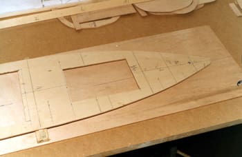
Deck Openings
This is the time to consider what openings you want to cut out to give access to the interior of the hull. I never put anything that can go wrong into a model unless I can gain easy access to it without butchering the hull. I also make any hatches as large as possible. You can usually position the deck hatches under the model’s superstructure. However in the hull that I am building this wasn’t possible, so I made the hatches as large as possible and used a false deck of Plasticard that fitted into the hatches on the model. Photo 6 shows the general layout of the hatches and the deck.
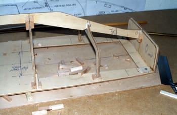
Having cut the frames, keel, deck and hatch openings you can then move on to marking the frame positions on the bottom surface of the deck, starting at the stem and working forward. Repeat this procedure on both sides of the keel. I have found that the most accurate method of building plank-on-frame hulls is upside down with the deck secured to a rigid piece of flat board. This ensures that when the hull is removed from the board it’s perfectly true without any distortion. This of course depends upon the keel being kept perfectly straight, and the frames not being forced into position during construction. On this hull there is a small amount of sheer. By placing a straight edge onto the plans between the bow and stern, I noted that the deck had a sheer of about 5/8in, the point of maximum sheer being at frame station 7.
Before securing the deck to the building board I placed a 5/8in thick packing piece between the deck and the building board at this position and tack glued it onto the board. The deck was fixed to the building board with three screws, one at the bow and two at the stern. Remember to put them in a position where you can remove them later in the build! Another thinner spacer was between the deck and the board around frame station 2, to maintain the sheer and to ensure that it wasn’t altered during the fitting of the frames.
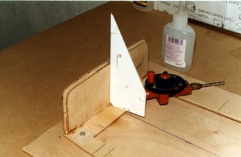
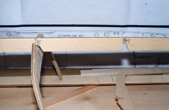
The first frame to be fitted and glued in place was transom frame 0. Before fitting, a piece of ply about 1/8in smaller all round was glued to the inside of this frame. This assembly was glued in place, ensuring that it was at 90 degrees to the deck, Photo 7.
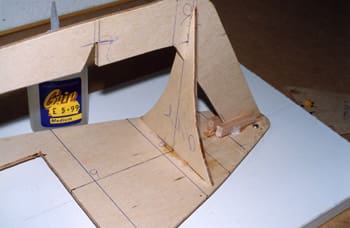
Using a piece of scrap ply as a spacer short pieces of 1/2in square balsa were glued to the dock at the bow and the inside of frame 0, as shown in Photo 8. With the keel placed in position the frame positions on the deck and keel were checked that they corresponded, using a square, Photo 9. Check also that the width at the top of each frame corresponds with the width of the dock at each location. If the width is slightly out, as it can be for a number of reasons, try moving the frame position slightly until it fits, and eventually glue it in that position. Photo 10 shows this being done with one of the templates.
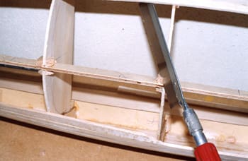
When the above accuracy tests have been completed you can move on to notching out the keel and frames. For simplicity, all the frames were fitted from the inside of the hull. This required one side of the notches on the keel to be cut at an angle of about 45 degrees, Photo 11.
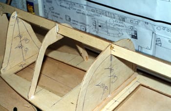
Once the notching out was completed the keel was glued in position at the bow and stern, and fitting the frames was commenced, starting from frame 5, which is in the middle of the hull. The accuracy of this initial frame is important. The frame was held in position and I looked along the length of the keel to check that it was perfectly straight. If the frame were pulling to one side, the notch in the frame would be slightly enlarged until the keel was straight. When satisfied with the alignment the frame was glued in place. Don’t worry if there is a largish gap on one side of the frame at this stage.
Continue to fit and glue the remaining frames in position using the same procedure, Photos 12 and 13. Some 1in long lengths of 1/4in square balsa was cut, and one of the edges was cut back to allow for the fillet of glue at each join of the frames to the keel. Those pieces of balsa were glued into all the places where the frames joined the keel and deck, Photo 13 again. This is why I stated that you shouldn’t worry about the largish gaps in the frame joins. After they are fitted they were cut level with the frames, Photo 14.
Checking Frame Accuracy
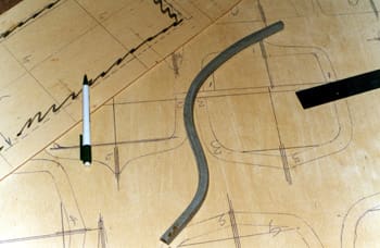
Before planking was started the accuracy of the frames had to be proved. This is one of the most important stages in building a good hull, so some time should be spent at this point. I generally find that no matter how careful I have been in cutting the frames, small inaccuracies do occur. Using a thin strip of flexible hardwood about three foot long, place it along the length of the hull at several locations and check to see if any of the hull frames either push the strip of wood outwards, or don’t touch it. The frames that stand proud will have to be sanded down and the ones that don’t touch it will have to have thin strips of wood of varying thickness glued on and sanded down. The bow of this model could not be planked due to its shape so planking was terminated at frame 9. The bow forward of this frame was constructed using P38 Easy Sand car body filler.
This concludes Part 1. In the next article planking of the model will commence.

