A World Wide Review of Warships and Warship Modelling by DAVE WOOL
Welcome once again to our regular sortie into the world of fighting ships. For the first time we have a research photo file on HMS Ark Royal after the 2007 refit. We also have Part 18 of the building of the Soviet Aviation cruiser Kiev and this month the boat bays are the subject, plus our usual Mystery Picture slot.
Research Photo File for HMS Ark Royal – Part One
Enjoy more Model Boats Magazine reading.
Click here to subscribe & save.
Over a number of years Ive had the privilege of visiting many warships including a number of aircraft carriers such as HMS Eagle, HMS Albion (the Centaur Class vessel) and the more recent ships HMS Invincible and HMS Illustrious, but not until now, HMS Ark Royal. I was delighted when I was informed that this famous vessel, now the Fleet Flagship, would be visiting the River Mersey in 2008. The name is of course no stranger to the Mersey. The third and fourth warships to carry that famous name were built at the Cammell Laird Shipyard at Birkenhead. For me this visit was a poignant reminder of my own family connections with that famous shipyard and of course the involvement my family had in the construction of both of those ships. As a young boy I still retain the abiding and vivid memory of seeing the fourth HMS Ark Royal slide down the ways on the 3rd of March 1950.
The present HMS Ark Royal was laid down at Swan Hunter, Wallsend on the 14th of December 1978 and she officially entered service on 1st July 1985. Unfortunately, due to political side stepping the entire class were given the euphemism through deck cruiser and not called an aircraft carrier. Also, originally the name allocated to this ship was not Ark Royal, but Audacious. The original concept of the Invincible Class was primarily that of a helicopter cruiser with no provision to embark the Harrier VTOL aircraft. However, the advantages of the Harrier were clearly demonstrated at the time and a decision to accommodate the Harrier VTOL aircraft was then made.
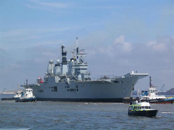
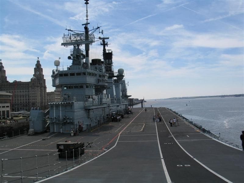
The design was a compromise and deck space was limited. Ark Royal was designed on a hull 210m long x 36m beam and displacing at full load, 20710 tons, Photo 1. This of course is much less than her predecessor which displaced over 53000 tons (in 1970) and was in her final years equipped with F4 Phantom fighter bombers. Propulsion for the current HMS Ark royal is provided by four Rolls Royce Olympus gas turbines developing 112000shp arranged in two engine rooms and driving twin shafts fitted with fixed pitch propellers. To give ahead and stern manoeuvrability the main propulsion installation includes triple reduction reversing gear boxes.
Aboard HMS Ark Royal
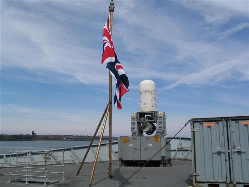
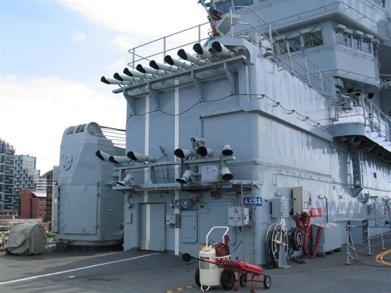
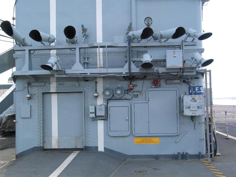
She is today a vessel that has undergone many changes in order to maintain her fighting efficiency. Unlike Invincible, HMS Ark Royal is presently fitted for close in defence with Phalanx which can be clearly seen in Photo 2. In March 1999 she entered Rosyth Dockyard for a major refit which altered the profile of this ship, but more on this as we progress.
The ski Jump
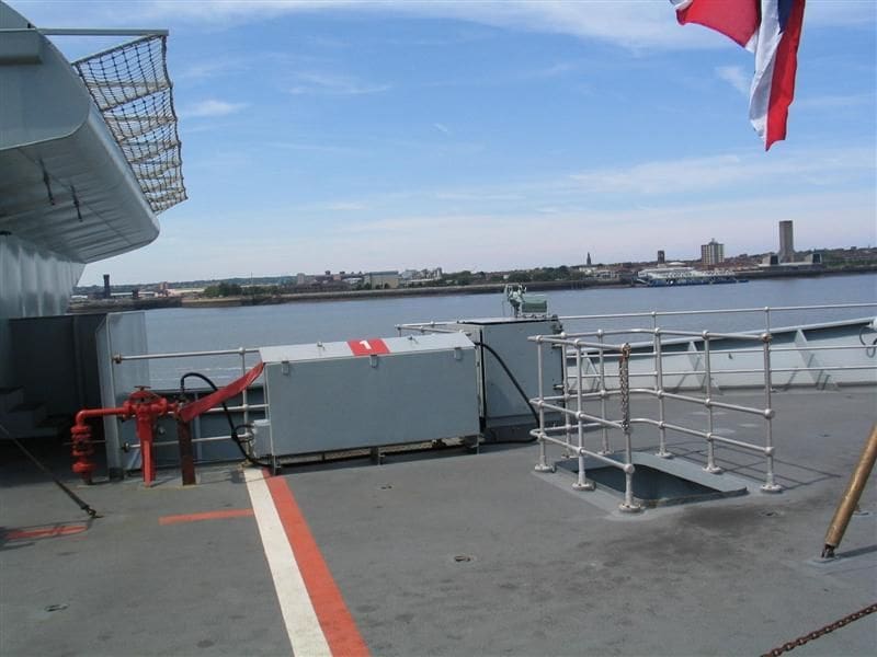
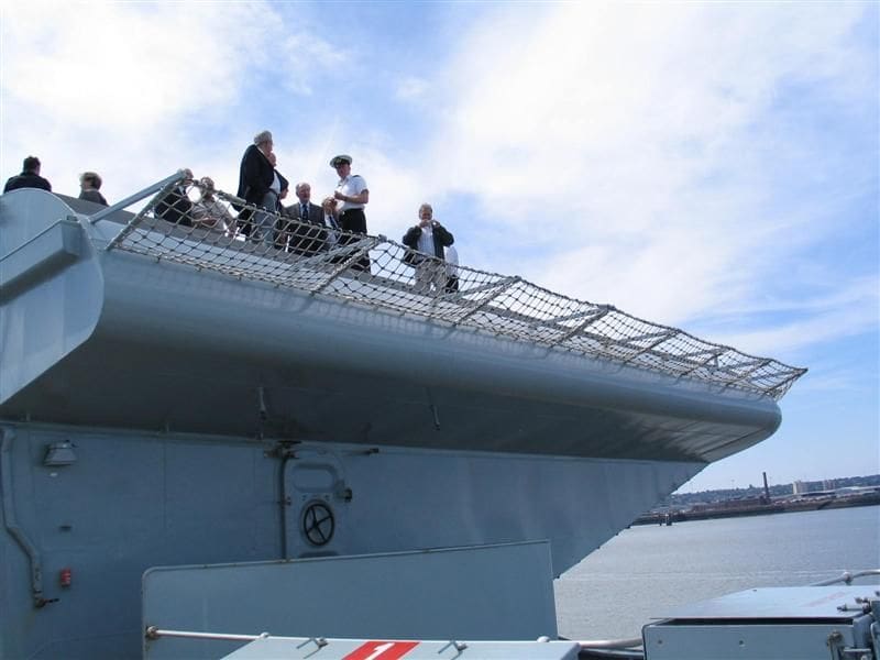
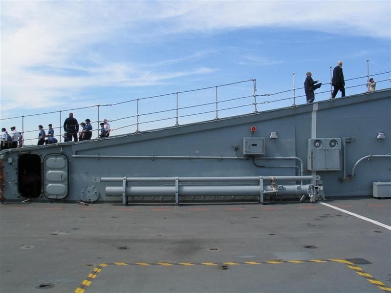
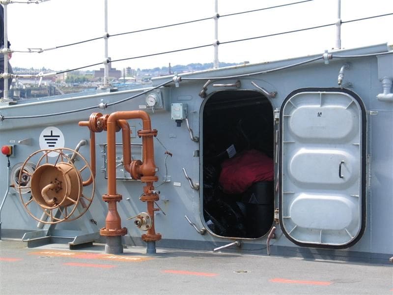
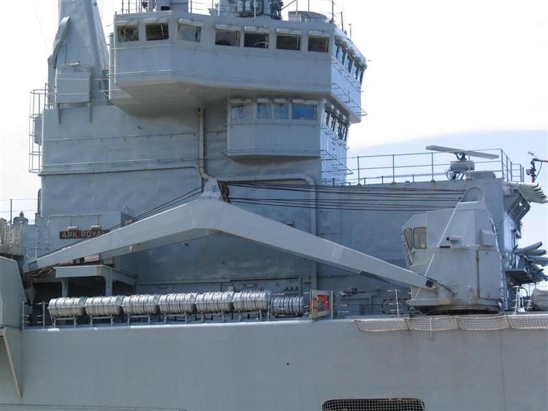
For now Id like to concentrate on the area of the so called ski jump and perhaps clear up some anomalies relating to this important feature. Both Invincible and Illustrious were originally fitted with a ski jump, the purpose of which is to allow rolling take offs. Initially the angle of the ramp was 6.5 degrees whilst on Ark Royal this angle was increased to 12 degrees during construction and the ramp was also 12m longer. In a later refit the angle was increased to 13 degrees . The following series of pictures convey in some detail the area in and around the ski jump. For example, Photo 3 concentrates on the area at the end and below the point of take off. Here the area is part of the flight deck. Back in 1985 this was a deck lower, but as this photo shows, access to the deck below or cable deck is still provided. In Photos 4 and 5 the detail immediately beneath the top of the ramp is clearly visible. Looking at the side, we have a view of the inboard of the ramp, Photo 6, and of course the access to the space within. Moving further back there is a jackstay, Photo 7 and in Photo 8, the access to storage space and a fire hydrant.
Flight deck
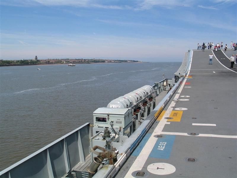
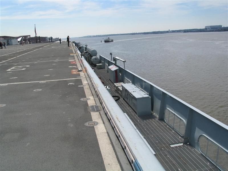
Interestingly, during the design process of HMS Ark Royal, the flight deck was given a half degree angle off the centre line to port, resulting in a marginal overhang of the ramp. The purpose of this was to clear the Sea Dart SAM launcher and its mounting. The effect of this can be seen when viewing from a vantage point at the top of the ski jump looking aft along the flight deck, Photo 9, and looking forward towards the ramp on the portside deck edge, Photo 10. Note the coloured markings on the deck edge. These denote points for fuel and water. Also, the small box like container which is a visual indicator with red and green lights and is used during helicopter operations. Remaining in the same location, but turning through 180 degrees, Photo 11 provides a useful modellers perspective looking aft along the walkway.
As I wrote earlier, in 1999 HMS Ark Royal underwent a major refit, which involved the removal of the Sea Dart launcher from the foredeck and the associated Type 909 fire control radars from both forward of the bridge and also aft of the superstructure island. For the former this allowed all of the fore and cable deck to be plated over, increasing the deck parking area by 8% and creating 22 new compartments below the 27 x 8m area of new flight deck . The existing Sea Dart magazine has since been utilised for weapons stowage for embarked RAF GR7 Harriers.
Island superstructure
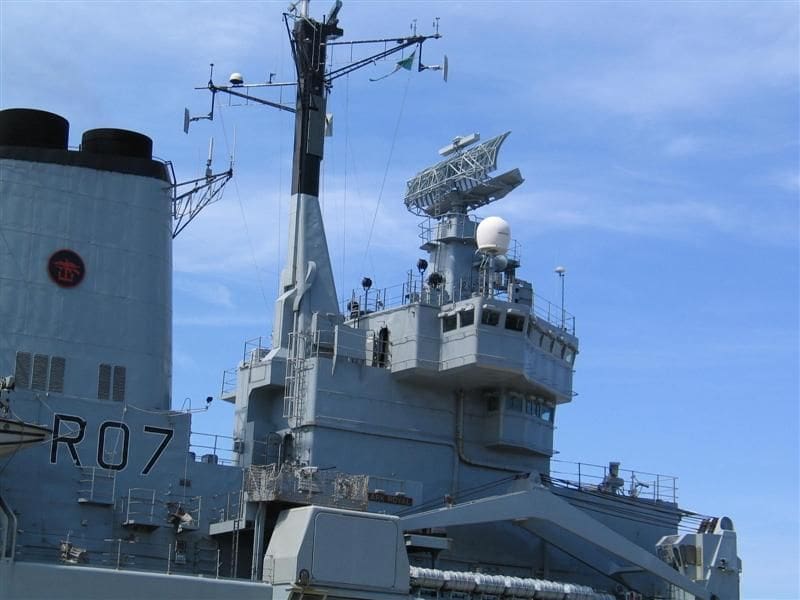
Its not surprising, but all of the models of Ark Royal I have so far seen show this ship as initially fitted and Ive not seen any models post-1999 refit. It is very early days yet to contemplate a model post-2007 refit! However, looking to the future this series of photos should provide some assistance to any modeller contemplating building HMS Ark Royal in this time span. One of the major aspects of the work undertaken in 1999 was the removal of the Type 909 radar. This area now is devoid of the prominent dome cover for the tracking radar and the vacant space is partly taken by one of two type 1007 navigation radar arrays.
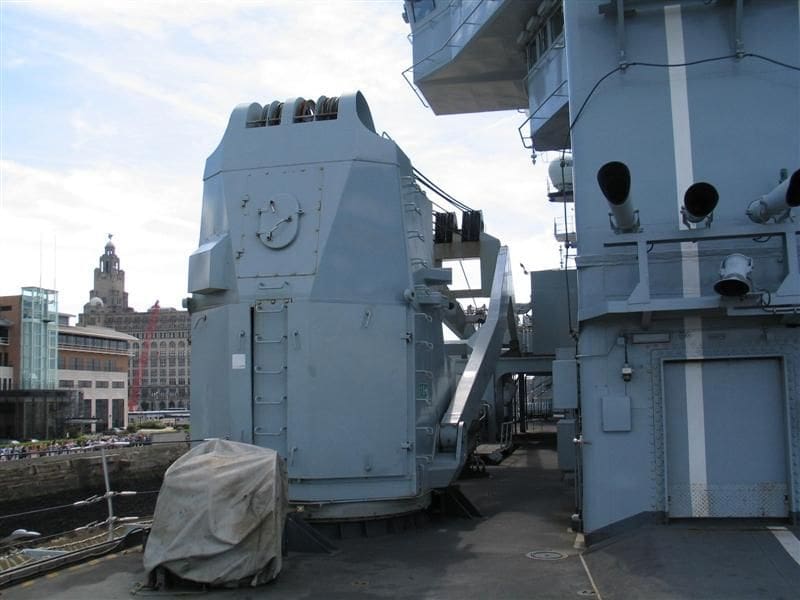
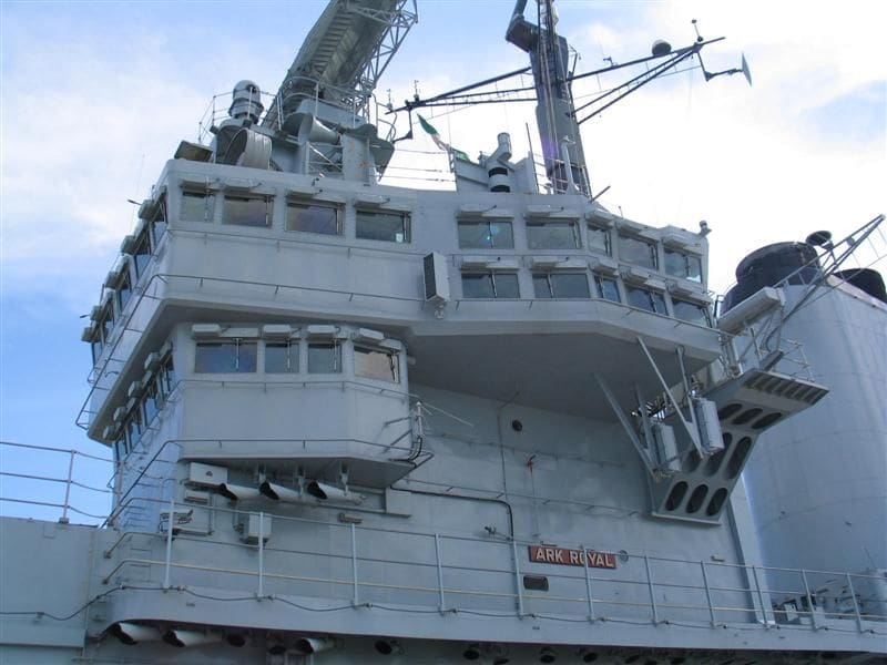
For those that have built models of any of the class, they may well consider that the revised profile is a change too far from their perspective, Photo 12, but all warships undergo some degree of change in their lifecycle and Ark Royal is no exception . Moving closer in gives us the advantage of seeing all the fittings on the lower half of this forward section, Photo 13. Little has changed at this level, as the pictures of the heavy lifting crane indicate, Photos 14 and 15.
As a model maker I have always expressed the view that you really can never have enough pictures of the subject being modelled and on any warship the centre of attention and the area where details are essential is usually the superstructure. In the modellers perfect world this may involve tens of pictures of just one area, but page space in articles such as this is limited, so I shall do my best.
The bridge
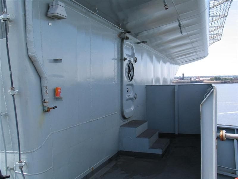
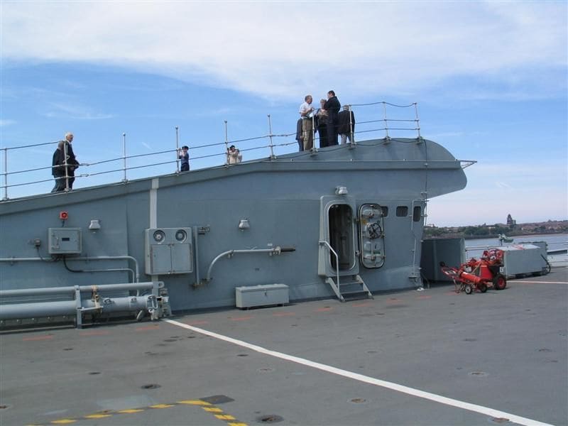
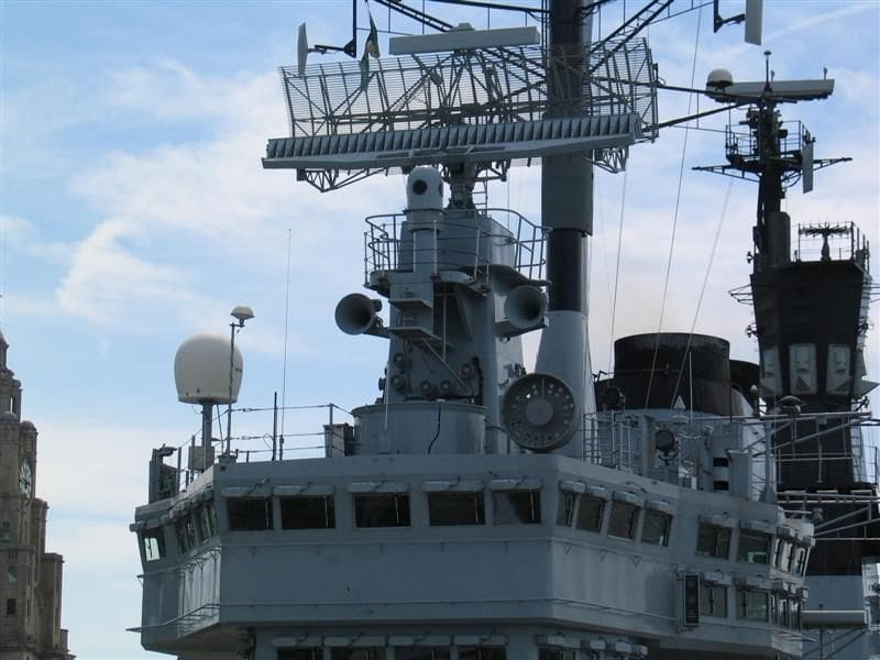
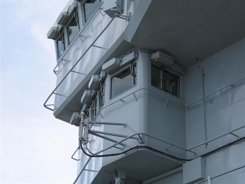
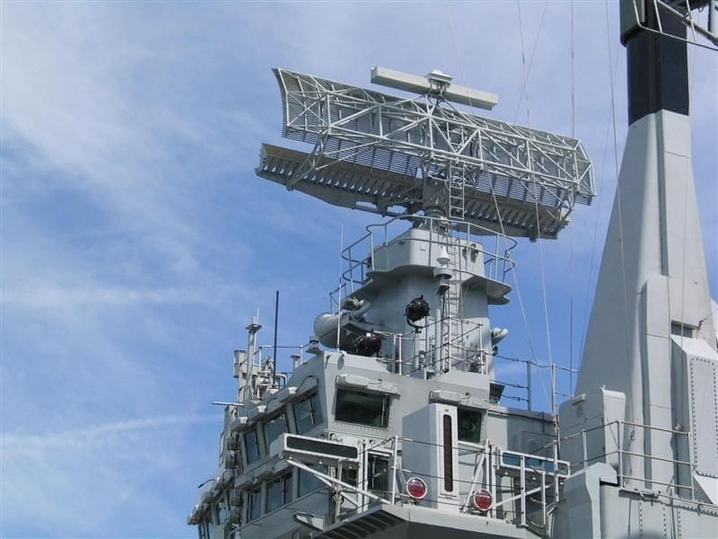
Some changes to the exterior of Ark Royal are very evident such as the removal of the Type 909 radar. Then there is the addition of fittings that improve detection and fighting efficiency. These requirements are filled by a new IR low and medium altitude surveillance pod which can be seen immediately forward of the existing Type 1022 long range (265km) air warning radar, a prominent feature when the ship was commissioned, Photo 16. Viewed to the right of the picture is the 135cm dish of the WSC-3 UHF satellite communications array. This array can also be used in a directional line of sight, ship to ship or ship to air link. Visible in the background mounted on top of the mainmast is the Type 996 surface and air search radar. Moving around to port and inboard side of the bridge is a detailed picture of how the side of the bridge is arranged, Photo 17. For those with an interest in building HMS Ark Royal the question may well be asked: What are the exterior features around the first level of the bridge seen in this picture but hidden in the perspective and the answer is in Photo 18.
Photo 19 focuses on the area around the rear of the Type 1022 array. The same picture also shows the detail to the rear of the foremast. Our final picture for Part One moves to the starboard side of the bridge, Photo 20. Next month there will be more pictures of the area abaft of the bridge and more close in detail of the deck fittings around the flight deck and island superstructure.
The building of the 1:144 scale Soviet Aviation Cruiser Kiev – Part Eighteen
Last month involved the basic construction of each of the motor boats carried by Kiev. This month moves on to the method employed on fitting out each of these motor boat recesses.
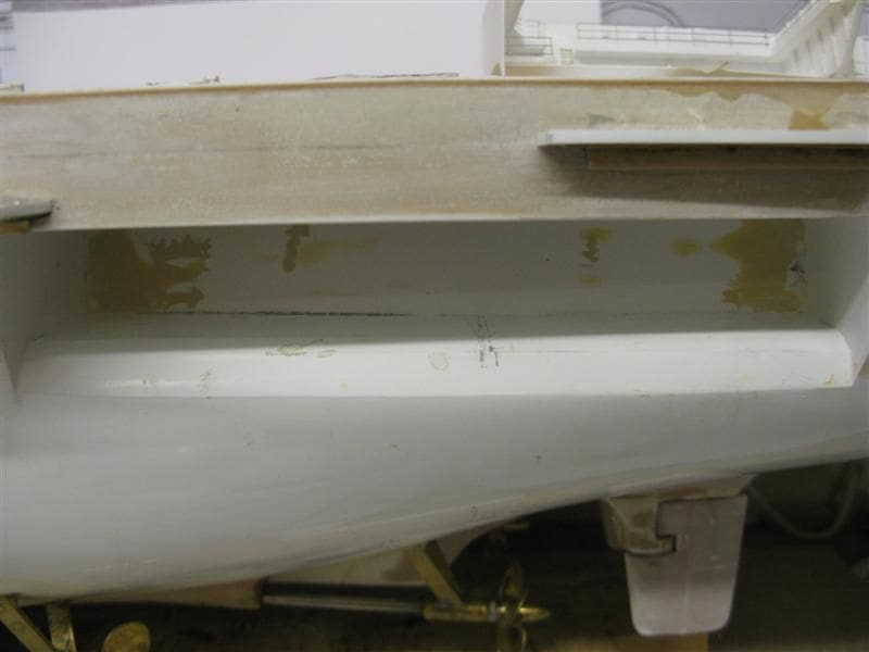
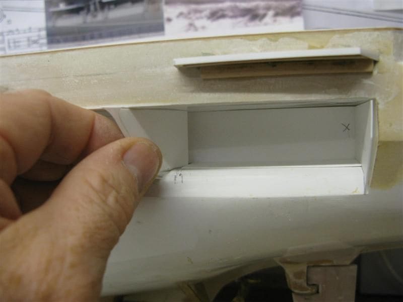
The initial problem faced was the fact that whilst the hull is moulded in GRP and not withstanding that it had undergone considerable modifications, the recesses aft for the ships boats were correct and required no remedial work and remained untouched. However those recesses were only accessible from outside the hull and this limited the work that could be undertaken within such a confined area. A solution was needed that would allow the interior of the recess to be fitted out, the boats to be secured to their falls and be painted.
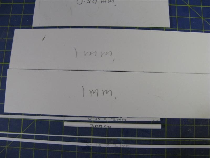
As with much of this model styrene was the material of choice, Photo 21. As a reminder, the principles of this build are centred on the methods used and not the exact dimensions required. The reason being that such methods can be applied to any model regardless of its scale. However it is of some relevance that the proportions of the recess are mentioned. The length of the opening is 176mm x 25mm deep x 26mm high. So pondering on how to work within such a confined area required a little lateral thinking, Photo 22.
Construction of the recess bays
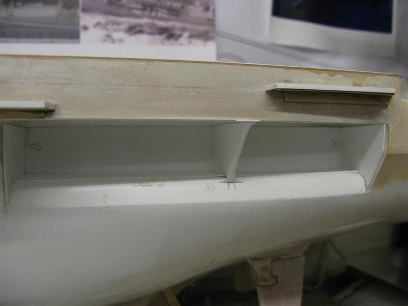
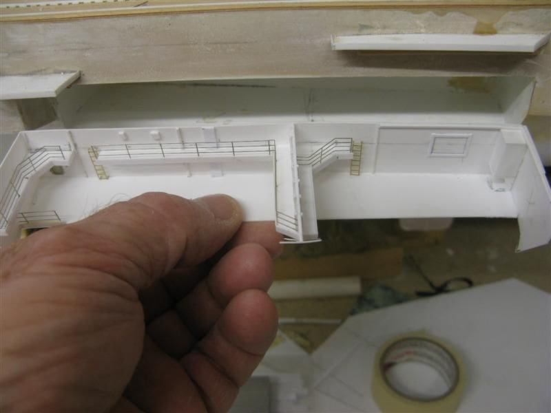
Given the circumstances, the simple answer that fulfilled all the criteria was to assemble a removable recess section. This would allow the interior, platforms, guardrails and fittings to be constructed and installed outside of the actual hull recess.
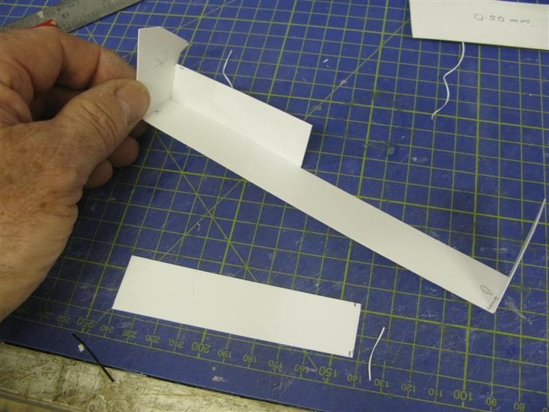
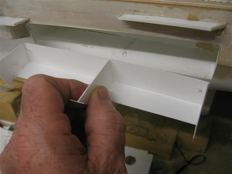
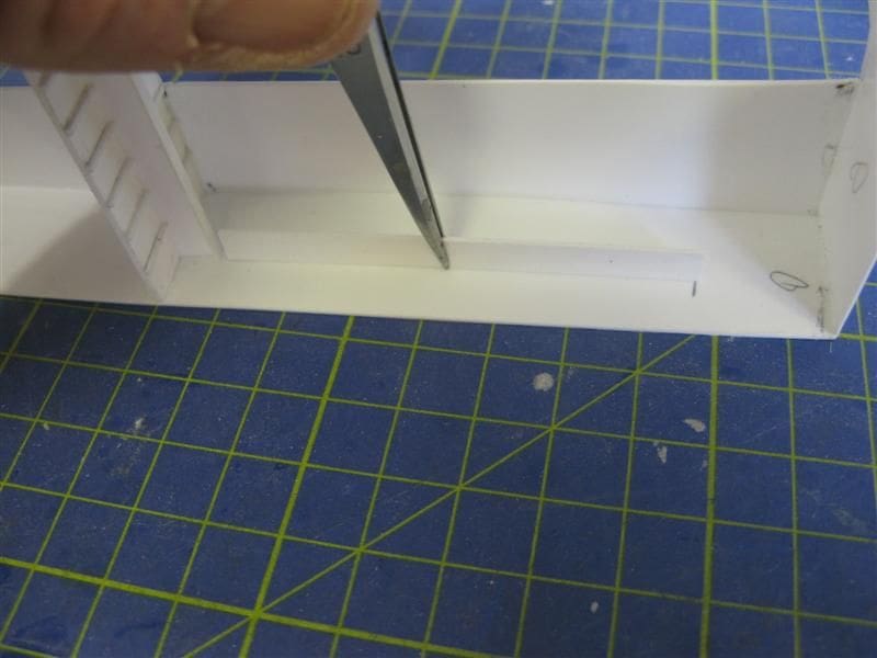
The exact dimensions were noted from the internal measurements of the recess. This included the back bulkhead, the base which is split into two, the two ends and the dividing centre bulkhead. Each of the latter two are shaped to conform to the differences in angle between the deck head and the contours of the lower level, Photo 23. The base is divided into two, noting that each bay is not of an equal length. The basic assembly can then be slotted into the recess and the centre bulkhead added, Photo 24. Confident that the centre bulkhead is fitted snugly into place a pre- shaped strip was bonded to the front of the centre bulkhead, Photos 25 and 26.
The davits
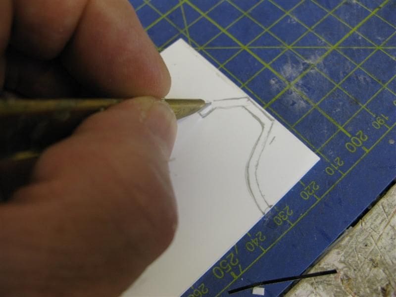
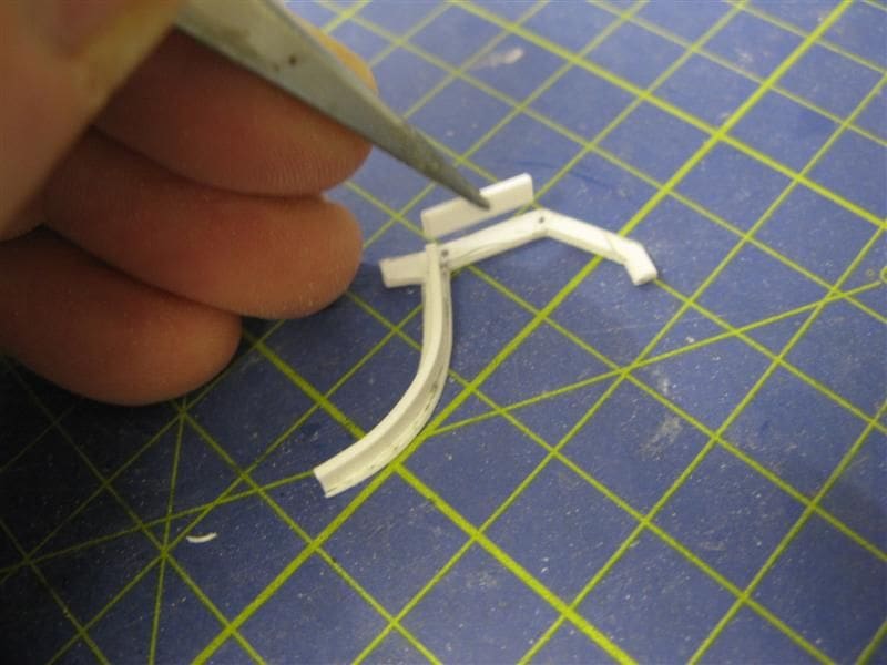
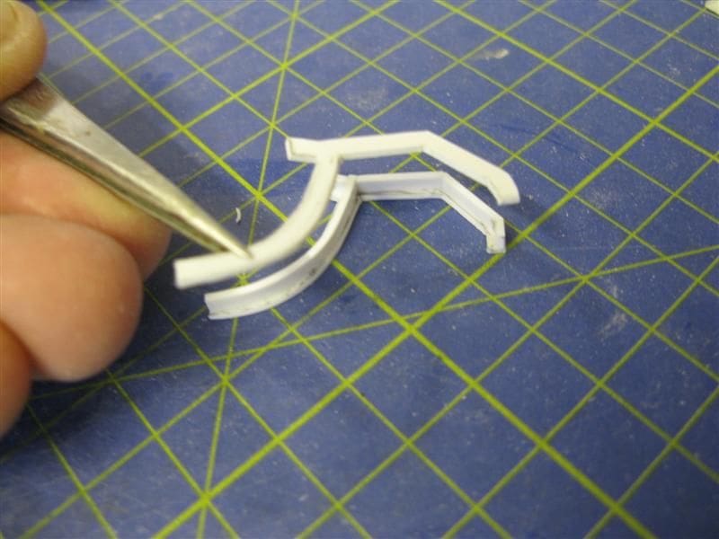
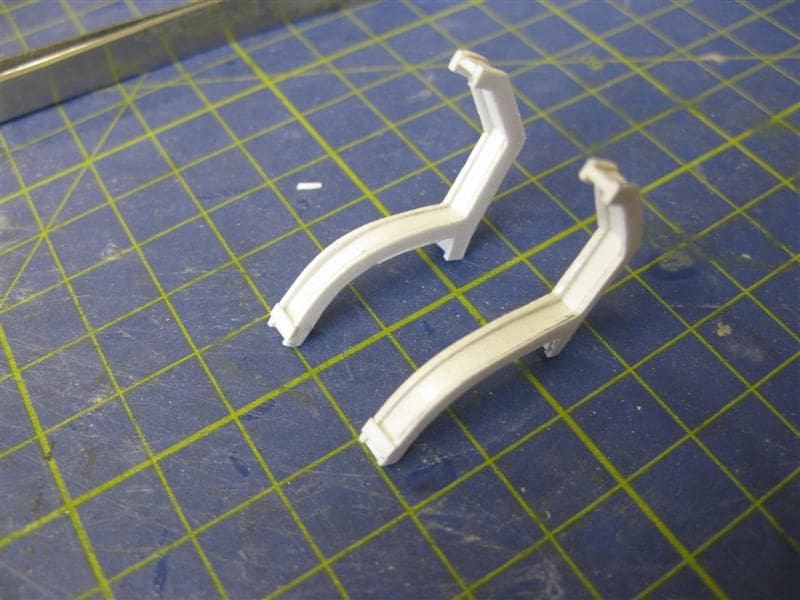
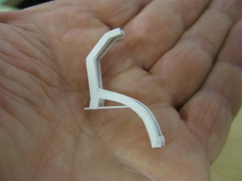
With little real idea of how the davits within the boat bay were actually shaped, reference to some pictures and inspired guess work was all that was available to me. The key parameter was the depth and height of the recess. Work started by examining the pictures to determine the shape and type of davits installed on Kiev. They were of a gravity type making use of what is termed the skid (or the lower half) and the curved upper section referred to as the cradle. This is the part of the davit that actually lowers the boat. On the model the chief problem was that there was insufficient room to fit both davits in separate parts. So for expediency the primary shape was maintained, but as a single section, Photo 27. When fitted it would be difficult to discern that the davit was in fact a single piece and not in two parts, Photo 28. The principle function of this type of davit is that the boat and cradle were to slide down the lower half or skid on rollers.
The idea adopted was to join two of the davit shapes together, but actually be separated by a spacer. This can be seen in Photos 29 and 30. In order to provide a seating whereby the davit could be well secured to the base, a short strip of styrene was place beneath the davit arm as in Photo 31.
Fitting out
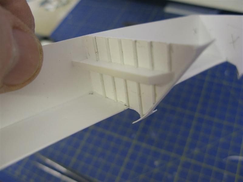
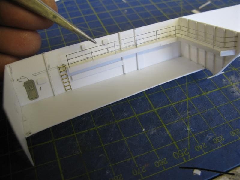
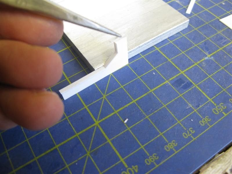
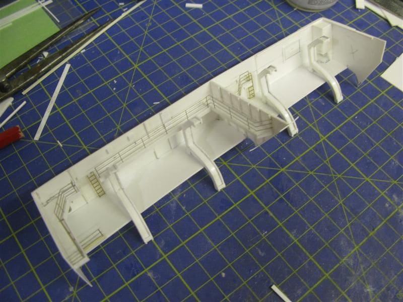
The next stage involved fitting out the interior of the recess. First the centre bulkhead platform was installed with vertical ribs, evenly spaced on either side, Photo 32. This was followed by the platform on the back inner surface, which also added strength, Photo 33. More of the fittings, for example the water tight doors, ladders and three bar rails were all added, Photo 34 . A further L shaped walkway was cut to size. Here a vertical strip was added to the edge that would eventually support the rails, Photo 35. This walkway was fitted to the inner face of the left hand side and the rail set in place, Photo 36.
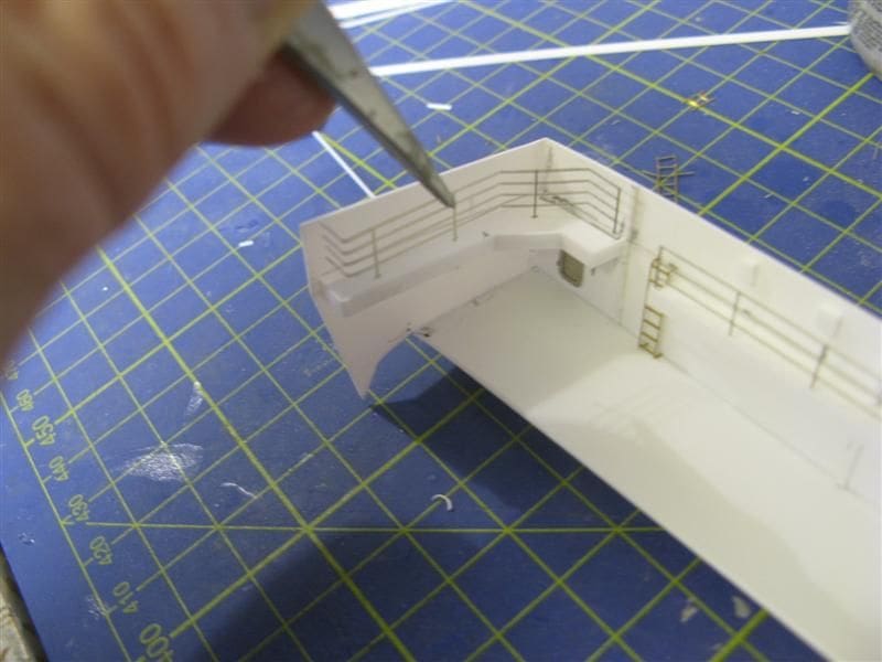
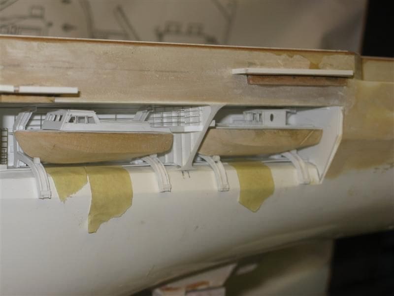
With most of the fittings in place, the davit locations were measured, marked and the whole assembly then fitted into the recess, Photo 37. The davits are the only fitting that is actually fitted in-situ as they have to be adjusted slightly to conform to the bottom edge of the opening. With the davits now in place the assembly is then once again removed from the recess, Photo 38.
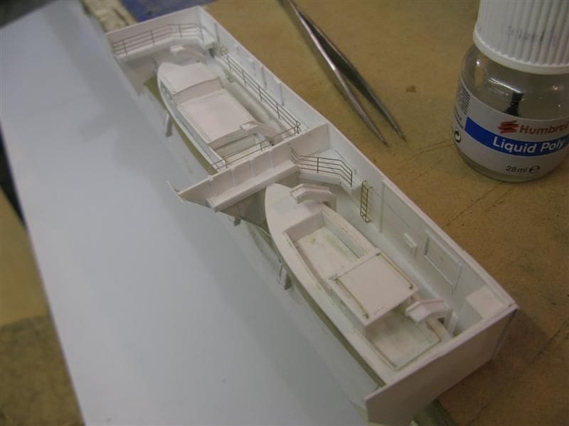
The ships boats which were discussed in the last issue, are placed onto the davits. As the assembly is clear of the hull openings, any adjustments required such as painting, adding the boat falls etc. is now a straightforward task, Photo 39.
After some adjustments to the boat positions, lengths of styrene rod were cut to conform to the width of the davits. These were then glued into place up against the lower part of the hull of each motor boat. This is because a gravity davit is actually in two parts, so to simulate that the rod represents the roller where the cradle joins the skid. The entire assembly was then replaced into the opening and each of the boats again temporarily seated, Photo 40. So now the whole assembly is virtually complete apart from painting and the final positioning of the boats.
Next month I shall discuss making the ships cranes and using a bit of lateral thinking to make life easier.
Answer to the February Mystery Picture
USS Alaska CB-l as of 3rd of April 1945. The clue was battle cruiser or cruiser?
Of all the warships built for the USN during WW2, one class of ship stands out perhaps for the wrong reasons and it was the Alaska Class. Theres little doubt that this huge warship, whilst possessing battleship dimensions was not a battleship by virtue of her protection and armament. Like the Fisher concept of the battle cruiser in WW1, the design and rationale was to some extent influenced on a political level by none other than President Roosevelt. USS Alaska was a warship nearly 250m (808ft 6ins) long by 27.67m (90ft 9ins) beam and was built at the New York Shipbuilding Yard at Camden between 17th of December 1941 and January 1945. USS Alaska was longer than the North Carolina and South Dakota Class battleships. Only the Iowa was longer at slightly over 262m.
However unlike the battleships mentioned here, the armour and armament was less. For example USS Alaska was fitted with 9 x 12 inch guns and had an anti-aircraft fit equal only to that of a large cruiser of the Baltimore Class. Perhaps the only real rationale for building such a warship was performance, but this was easily matched by the fast battleships of the Iowa Class with their 33kt maximum speed. Thus all the so called pluses that the concept of the battle cruiser was meant to deliver were cancelled out with an inherently weak armour disposition and questionable turning characteristics.
There was little doubt that the Alaska class were considered poor value for money when compared to the Iowa Class battleship. In fact the construction of the third vessel CB-3 USS Hawaii was suspended early in 1947 whilst the remaining vessels CB-4 USS Philippines , CB-5 Puerto Rico and CB-6 Samoa were all cancelled in mid-1943. Interestingly and unlike many USN heavy cruisers and battleships of the period, the location of the aircraft catapults was sited amidships on either beam which perhaps reflected the arrangement that was in place on earlier USN cruisers such as those of the Astoria and Indianapolis Classes. Alaska saw action in the Pacific War, but was scraped in 1961.
Despite all of these shortcomings behind both Alaska and CB-2 USS Guam were attractive warships and possessed a distinctive profile that makes these USN battle cruisers a good subject as a working model. For those interested, a comprehensive set of drawings and photographs of USS Alaska are available through Floating Dry Dock, website: www.floatingdrydock.com

