A World Wide Review of Warships and Warship Modelling by DAVE WOOLEY
.jpg)
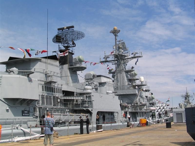
INS Mysore D60, one of the three ship Delhi Class that also includes INS Mumbai.
Welcome once again to our regular sortie into the world of fighting ships. This month sees the second and final part of our Photo File on the Indian Navy DDG Mumbai and we also continue with Part Fifteen of my in depth build of the Soviet Aviation Cruiser Kiev, detailing the handrails, watertight doors and preparations for glazing.
Enjoy more Model Boats Magazine reading.
Click here to subscribe & save.
Photo File for INS Mumbai – Part Two
For a heading picture this month I have included a picture of INS Mysore, another of the three ship class for comparison with the heading image of INS Mumbai D62 printed in the November issue. The concluding photo last month focused on the starboard side of the ship at the base of the foremast and continuing this sequence, Photo 1 shows the arrangement just forward of the RIB. To the right of the picture is the Front Dome, a C Band missile illuminator and guidance radar for the SA-N-7 SAM system.
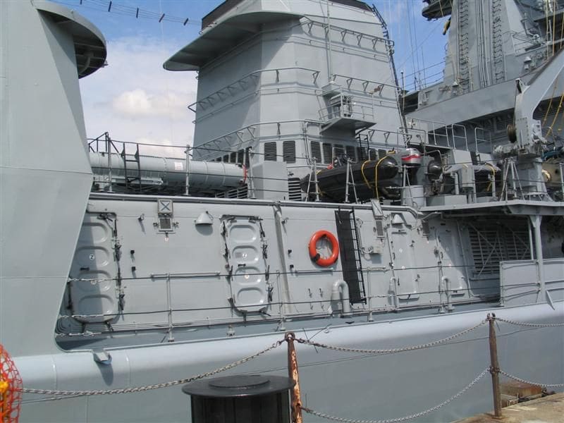
Moving further aft, Photo 2 brings the funnel casing into view and the detail abaft of the foremast. Note the series of rails that surround the casing and Photo 3 reveals the deck housing detail. I made mention last month about the strange amalgam of Russian and RN fittings. Looking closely there are two RN panel type watertight (WT) doors, but immediately below the inflatable is a recessed panel door in common use on Russian designed warships.

Base Tilt and the AK 630 CIWS
Although the Mumbai is built in India to Indian Navy specifications and requirements, the CIWS (Close in Weapons System) is of Russian origin as of 2005. I think it is worth mentioning, that pictures such as these only relate to a specific point in time and changes to these weapon systems effect not only the specification, but will also alter the structural appearance.
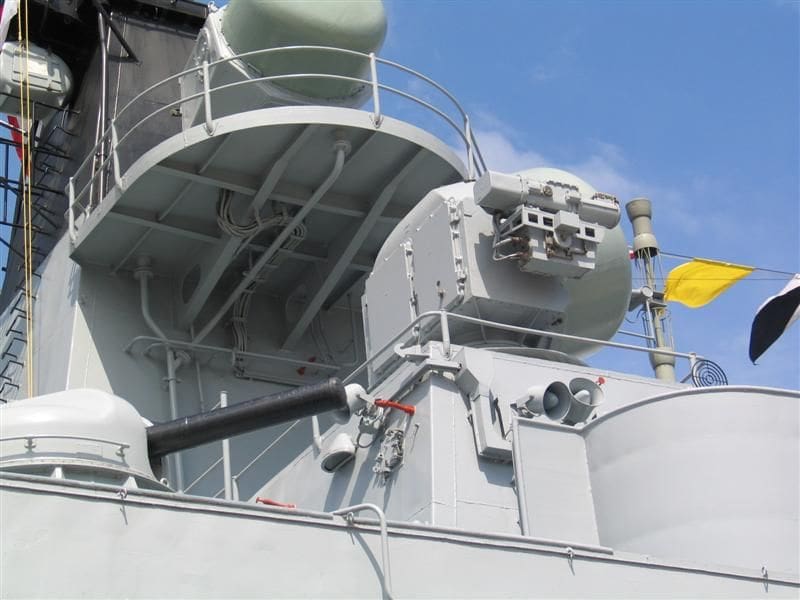
The AK 630 30mm Gatling type gun and the Base Tilt (Nato Code) was discussed in relationship to the Kiev in MB issues 695 October 2008 and 696 November 2008 respectively. On the Mumbai and as these pictures show, there are four AK 630M 30mm/54 calibre guns (two either side) clustered almost amidships on a raised platform extending out from what would be 02 deck, Photo 4. Just outboard of the Base Tilt guidance radar is a sighting platform.
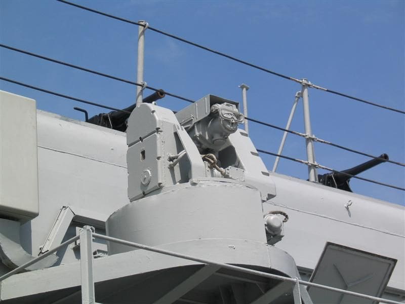
Focusing closer into the Base Tilt, it will be noted that there are noticeable differences to the type fitted on Kiev, but the function remains the same. The AK630 30mm Gatling gun is unlike the Nato equivalent Goalkeeper and Phalanx CIWS which have a built in tracking radar and are designed as a bolt on system, whereas the AK630 was first introduced into the Soviet Navy in the mid 1970s, but relies on a separate tracking radar. Capable of a 400 round burst of fire, each mounting contains 2000 rounds and a 1000 round reserve bin, but unlike Goalkeeper and Phalanx, the AK 630 requires a cool down period between each 400 round burst. There is an upgraded version known as the AK630M1-2 with a higher burst rate of fire and a reserve of 4000 rounds.
In Photo 5 the Base Tilt or MR123 Vympel as it is also known is fitted with a TV camera and laser ranger. This can be clearly seen attached to the side of the radar casing. Unlike its Nato counterparts, the AK630 and its associated Base Tilt are not fully autonomous in operation and require operator involvement at the target identification stage – only then is the system transferred to auto-tracking. There is no information available as to the ECM (Electronic Counter Measures), clutter rejection and jamming capabilities, or the systems ability to track one target whilst engaging another, which is certainly a feature of Goalkeeper. Like all last ditch defence systems, the total reaction time from commencing operation to engaging the target is paramount to the defence and the survival of the ship. With the Goalkeeper this is just 5.5 seconds. Since these photos were taken, only INS Mumbai of the class has not been retro-fitted with the additional advantage of the Barak point defence missile system.
The Barak missile and Elta tracking radar
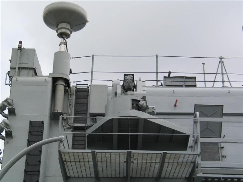
Deviating from INS Mumbai for a moment, complementing the CIWS of the AK630 30mm Gatling gun, both INS Mysore and INS Delhi, have been fitted with the Dual X Band and KA Pulse Doppler Elta radar plus the Barak missile system and Photo 6 is of one of those modified ships. The system as installed on these DDGs is not with out its detractors within the Indian naval establishment, but the performance of the system according to Elta is exceptionally good, especially when you include the high anti-clutter and ECM capability, which is perhaps lacking on the AK630 gun system. The Elta Cassegrain radar replaces the Base Tilt, but retains the optical tracker and laser ranger element. Each of the two eight cell launchers is mounted on either beam on 02 Deck. The Elta radar can acquire sea skimming missiles out to a range 16km and higher flying aircraft at double that range.
The Barak missile is a point defence missile and possesses a very fast reaction time of 30 seconds from launch to maximum range with a speed of 580m/s. Originally developed for the Rashef Class FAC boats and the Saar Class corvettes of the Israeli Navy, the Barak missile was intended to combat highly manoeuverable anti-ship missiles. The rocket motor has been designed to have three levels of thrust. The first phase is a low initial boost to avoid undue damage to the launching vessel, followed by a high performance second phase, stepping up to a final stage of sustained thrust to target.
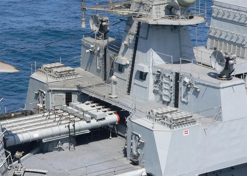
Torpedo tubes
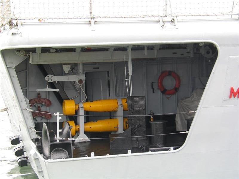
Note that on 01 Deck a quintuple set of 533mmASW torpedo tubes for the Russian manufactured SET 65 E active/passive acoustic torpedoes. Additional to the conventional torpedo is the 15km range SS-N-15 rocket torpedo also known as the Shkval or Starfish.
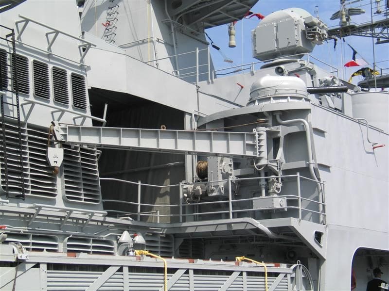
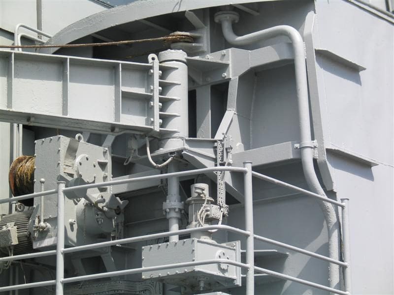
Moving aft, but remaining on the starboard side and mounted directly onto the AK630 platform is a lifting crane for deploying the gangway, which is stowed on the main deck, Photos 7 and 8. In the same location on the port side is a davit-launched motorboat.
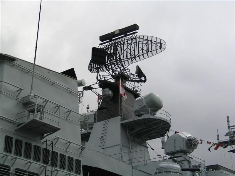
Early warning radar
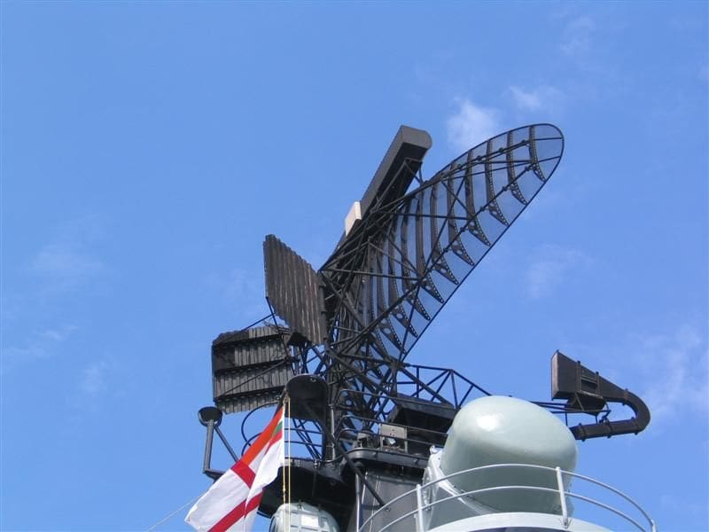
Mention was made as to the Indian technical ability for using dissimilar equipment and interfacing them together. In part this is true, but it is not the whole story. The Delhi Class like much of the Indian Navy is an amalgam of differing weapon platforms and electronics. The same could be said for the early warning radar. Mumbai is fitted with the Bharat RALW-02, Photo 9, which is manufactured by Bharat Electronics, a large and expanding company based in the South West of India and now referred to as the Silicone Valley of India. Although the RALW-02 is of Indian manufacture, the original design is based on the Thales LW-02, a Dutch manufactured radar that dates back to the 1950s. Performance has been much improved now with higher levels of anti-clutter, ECM resistance and a range exceeding 280km up to a height of 85000ft.
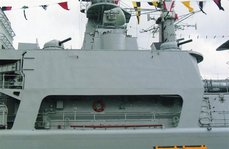
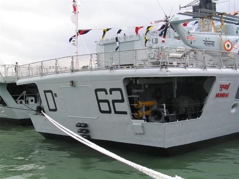
A more detailed shot of this radar can be seen in Photo 10. Note the stabilising vanes and the IFF transponder which is the elongated device fitted at the top of the parabolic reflector. INS Mumbai is not overtly radar reflective or stealthy, but is a rather good-looking warship, Photo 11.
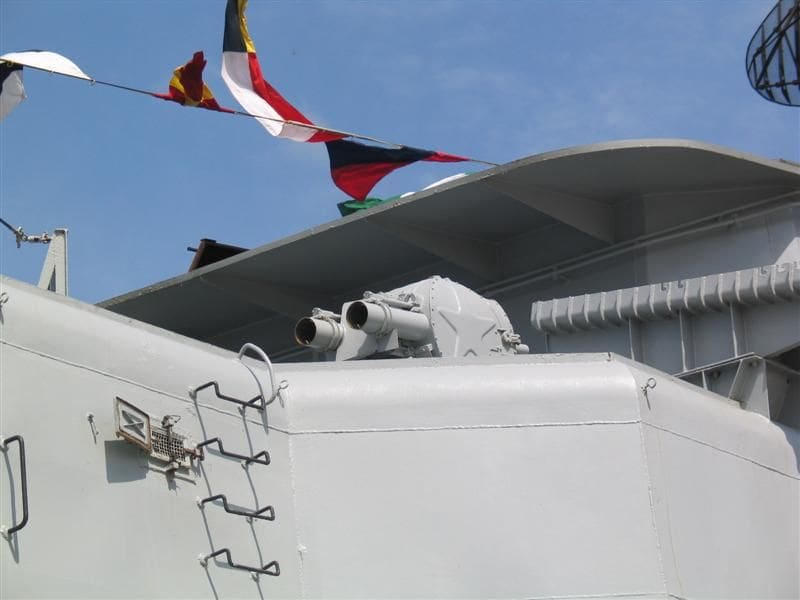
Decoy launcher – PK-2
Ive seen this type of decoy launcher on a number of Soviet built warships and it is usually sited on the main deck and close to the deck edge. However on Mumbai the PK-2 is mounted on 01 Deck. It is essentially a twin tube, trainable 152mm active decoy launcher. Its been stated that the use of active decoys is preferable to passive decoys, on the premise that passive or large amounts of chaff can impede the ships own radars. Loading is from the deck below and akin to the RBU 6000 ASW rocket launcher (discussed last month). The barrels come to the vertical and the one metre long rocket assisted decoy is automatically loaded into each of the tubes. Adjacent to each of these launchers is a fixed chute. Originally thought to be for disposing of unused rounds, it would appear that this chute is directed outboard to deploy an IR (Infrared) round directly into the water, Photo12.
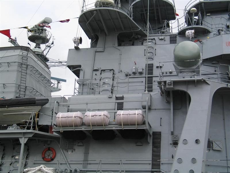
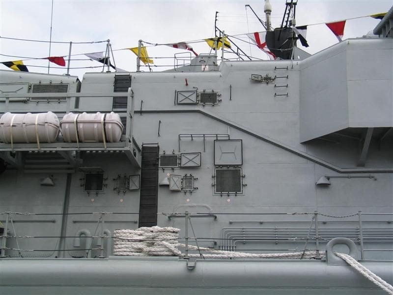
Fixtures and fittings on the aft starboard side
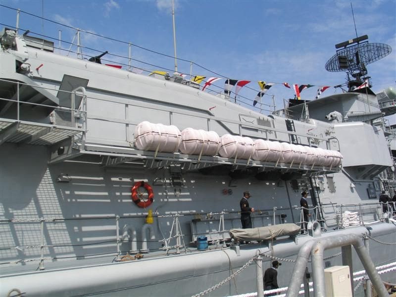
Moving further aft along the starboard side a large number of small fittings come into view. These range from various sizes of vents with covers, to pipework and deck level gooseneck vents, Photo 13. In Photo 14 we can gain an idea of how the inflatable liferaft containers are secured to a platform at the side of the hangar. At the extreme left edge of the picture is a platform supporting the starboard Electro Optical (EO) tracker that was discussed in detail last month. Generally these devices are located close to the 30mm CIWS, but here it is twined with the Front Dome guidance radar sited either side of the mainmast for the SA-N-7 SAM launcher mounted on top of the hangar roof. This is just visible in the header picture, but the EO device on its power mounting is seen here in Photos 15 and 16. Its worth mentioning that the access ladders shown in the latter have been given a very dark blue background. The purpose of the circular plate like device mounted on a telescopic arm is not known, but given its location close to the hangar doors, its probably associated with aircraft operations.
Hangar and air group
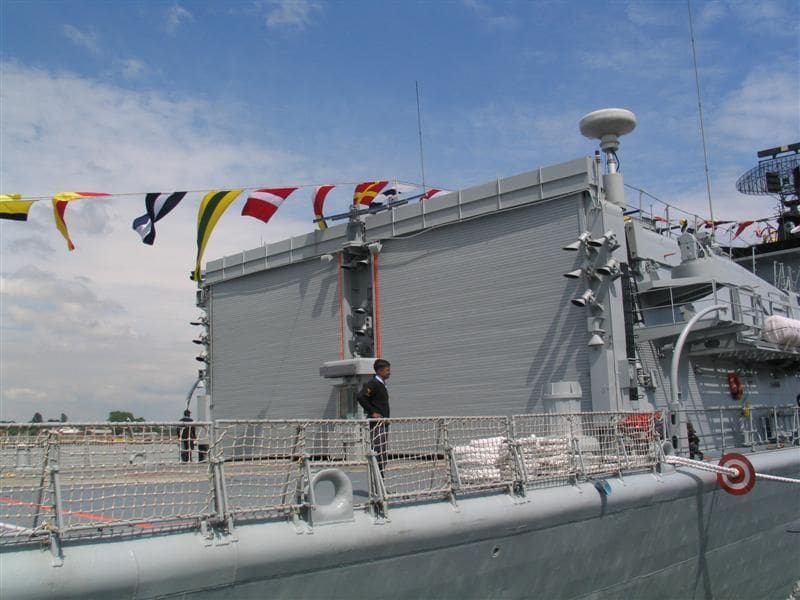
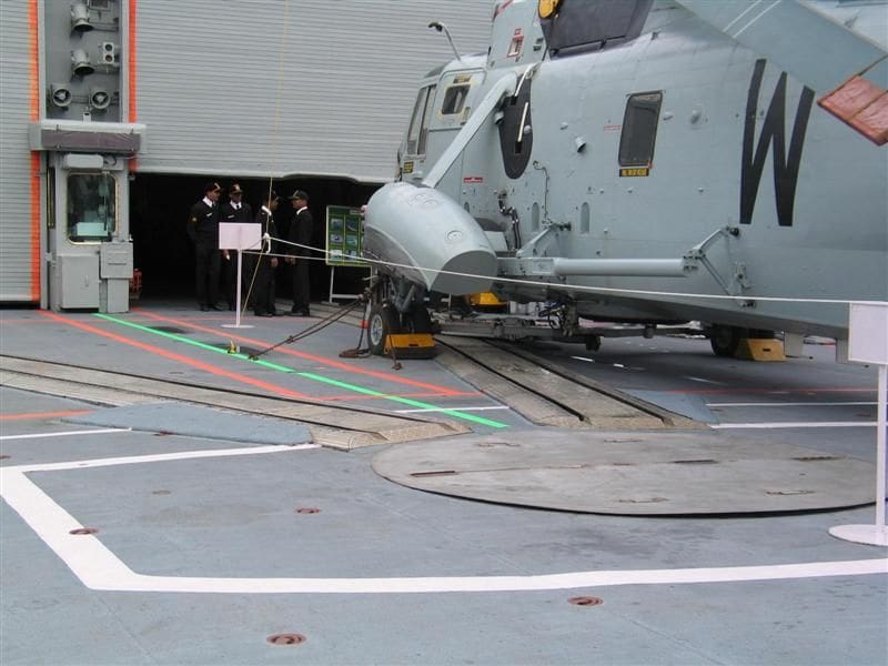
The following two pictures show the large hangar facility, which can accommodate two Sea King Mk. 42 helicopters, equipped with Sea Eagle anti-ship missiles or ASW torpedoes. It appears that some form of haul down system is used, but there is no clear evidence of this that I could see, except for a covered section in the centre of the flight deck and rails that could form part of a RAST type recovery system. It is more likely that it is a means of moving the helicopter into the hangar, Photos 17 and 18.
Right aft
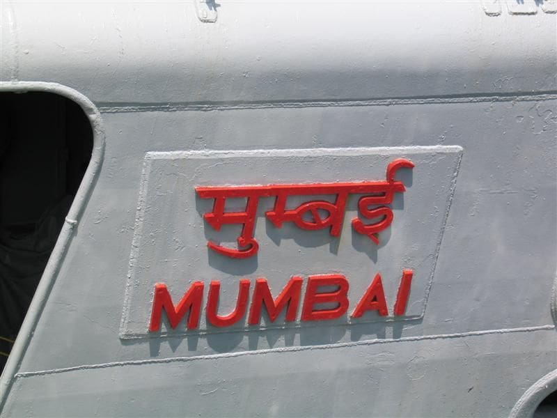
Many warships have their names in raised lettering right aft on the side of the hull in the language and lettering of the country of origin, but you seldom see this clearly in any photo tours. INS Mumbai is slightly different as the ships name is in both Hindi and English, Photo 19.
ASW detection
INS Mumbai, like many warships of this type, has a comprehensive ASW suite including the Bharat manufactured hull mounted sonar and VDS (Variable Depth Sonar) seen here in Photo 20.
Our final picture of this tour shows the arrangement right aft. It appears that an opening in centre of the stern was envisaged, but has since been plated over. This may have been the original point for trailing the VDS. All the handling equipment for the VDS is of Indian manufacture, Photo 21.
Conclusion and a view to the future
As mentioned in Part One, the Indian Navy is undergoing a significant expansion with all types of warships. Although Mumbai and her sisters of the Delhi Class lack the refinements of radar reflective surfaces such as those seen on the RN Type 45s, the direction and design of future Indian Navy DDG construction is certainly along that route. In September 2003 construction commenced on Project 15A, the Kolkata Class ships, the first of which is scheduled to enter service in 2010.
A full stealth design of DDG, Project 17, has been given the green light and this I am lead to believe is to be equipped with the 24 cell Barak 2 point defence system and the highly effective Kashtan point defence missile/gatling gun combination, see issue 655 MB June 2005 for detailed photos. The main gun of choice is the low radar reflective Topaz 100/59 calibre naval gun. No firm dates are forthcoming, but it does seem likely that this new class of DDG will be in service some time between 2012 and 2015.
Along with this broad naval expansion, which will include SSNs and aircraft carriers, there is a strong commitment to the Indian naval doctrine of defence of their national interest and taking responsibility for their own waters.
The building of the 1:144 scale Aviation Cruiser Kiev Part Fifteen
Continuing the build of the Kiev our attention shifts to the louvred vents, photo etch doors and handrails, aerials and glazing deck housings.
Vents and louvres
Sited along the sides of the island superstructure are a series of vents. Finding a suitable material that would simulate the louvred effect on these vents without resorting to costly photo etch was not a problem. The solution was similar to that used on my Moskva – a sheet of corrugated styrene . The width of the corrugation was important as there are a number of widths available, but this particular size not only resembled the louvres on Kiev at 1:144 scale (standard sheet measurements 175mmx 300mm x 1.3mm) but being styrene was very easy to cut, a useful advantage when not all of the opening are of the same size, Photo 22. Corrugated styrene is readily available from model railway shops.
When the island superstructure was being constructed (Part Three, issue 685 Dec 2007 MB) the vents were opened up and an internal backing inserted. This would allow progress on the main superstructure to continue and for the vent covers to be installed at a later date and more importantly once cut to size they could be removed for painting. This is because the louvres are a darker grey than the general overall colour. Photo 23 shows the larger of the two types of vents cut and temporarily placed into the side of the superstructure. In Photo 24 all of the louvres are in place and the same procedure is repeated on the outboard side of the superstructure.
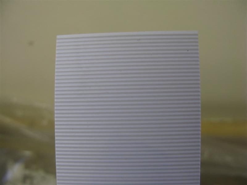
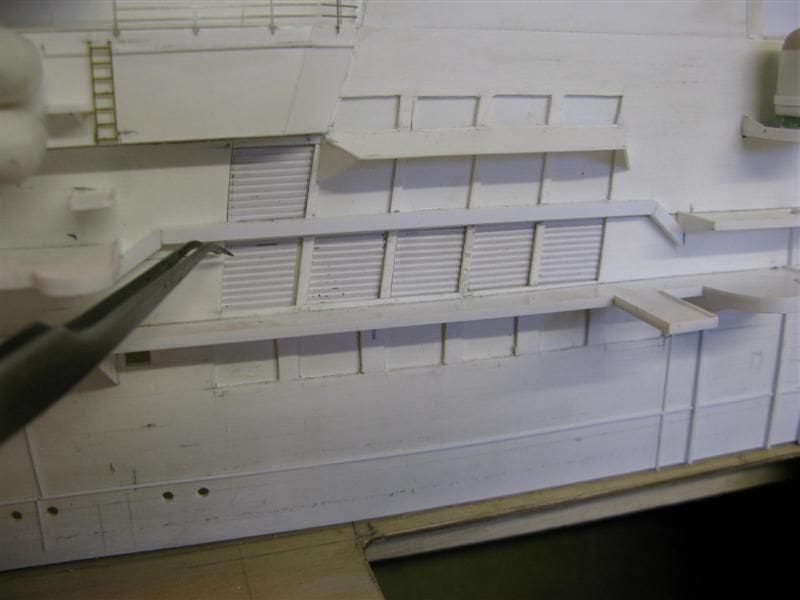
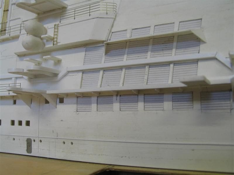
Photo etchings
Up to this point Ive not depended on PE (Photo etchings) to any degree. However there are certain fittings, particularly at 1:144 scale where PE can produce a more refined job. Watertight doors and handrails are two examples.
Watertight doors
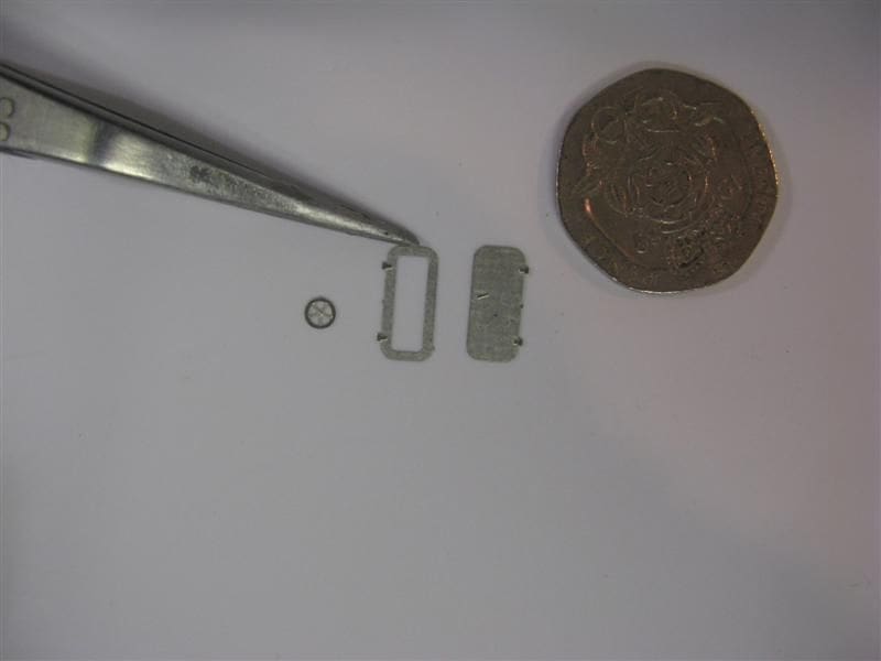
Kiev is fitted with single panel watertight doors, some having a series of dogs around the edge to secure them, others having a central hand wheel for the same purpose. This is the type shown here and produced by Gordon Brooks as part of a series of bespoke fittings for Kiev. The door comes in three parts: Locking wheel, outer surrounding edge and the recessed panel, Photo 25. Assembled and placed in position, you can judge the results for yourself, Photo 26.
Handrails
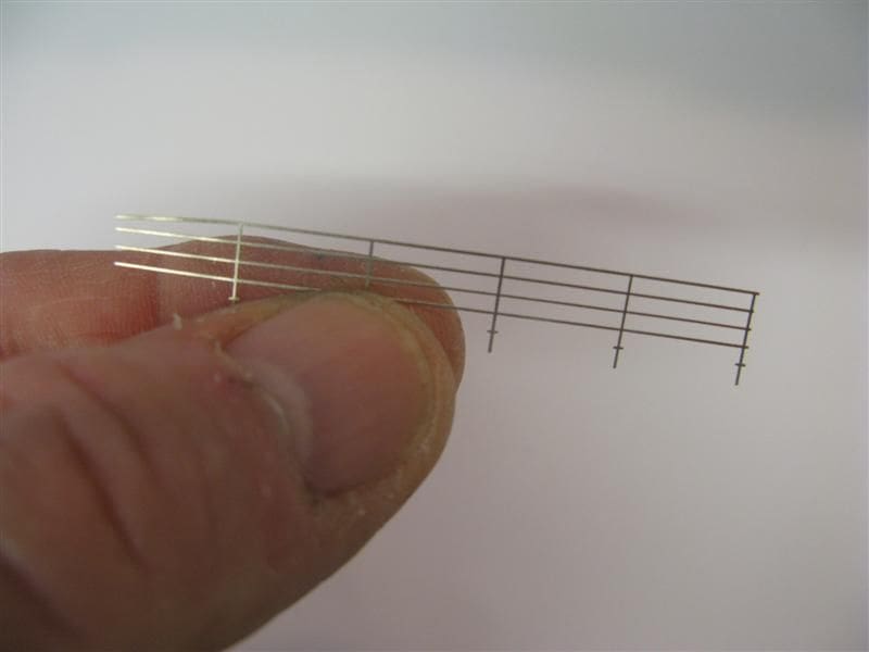
Kiev is blessed (or cursed) with more than one type of handrail. In fact there are three distinctive types; 3, 4 and 6 bar. The 4 bar versions are used on much of the superstructure and sourcing these rails created some headaches. At 1:144 scale using individual stanchions and then threading the rails through was ruled out , even if such a product was available, Attempting this would have really stretched my ability and my sanity. However after consulting both Peter Hall of Atlantic models, email: [email protected] and Gordon Brooks, email: gordon@ tinworthrestoration.ndo.co.uk, I supplied drawings for the types required and both set to work producing the stanchions required. You might ask why from two different manufacturers? The reason was that I wanted to try these specialised rails in two different types of metal. Peter produced the rails in brass etch whilst Gordon made them in etched nickel silver, the latter being slightly more expensive.
Both materials have their own particular qualities. Peter Hall is well known for his exceptionally fine PE at 1:350 and 1:700 scales. The brass was indeed finer in detail, but the nickel silver was slightly stronger. If it were a static model then I would have chosen the brass etch, but being built as an operating model, strength was also a factor to consider, see Photo 27.
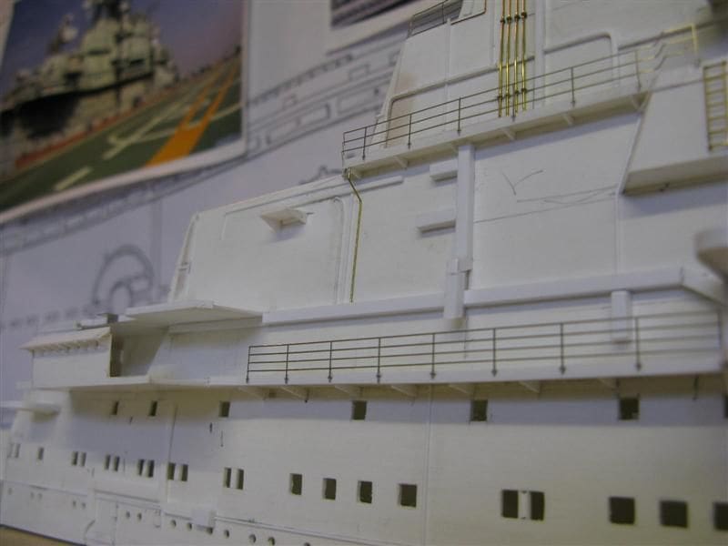
Many of the rails on the superstructure of Kiev are of solid bar and the stanchions spot-welded to a raised metal strip on the edge of the platforms. On the model each length of rail was cut to size and fitted using superglue to the raised edge of each platform, Photo 28. Not all of the stanchions are secured this way. Others are imbedded into the surface of the deck. Those along the deck edge are different again which will be dealt with in a future issue.
Whip aerial
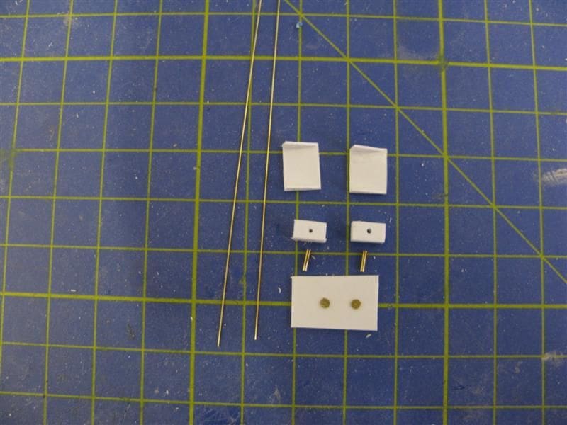
Kiev has a number of whip aerials and of course inevitably they are not all the same. This shown is a simple aerial with a rectangular base. For this task 0.33mm brass wire provided the aerial with a slightly larger section of 1mm o.d brass tube into to which the aerial is inserted. Both 1mm tube and aerial are then imbedded into a rectangular styrene base, drilled out to allow the tube to fit. Dividing the aerial from its base is a circular insulator and this is simulated using a very small PE hand wheel, Photo 29. At the top part of the picture are two small platforms for the base of the aerial to rest upon. The assembled aerial can be seen in Photo 30. All that remained was to fit the platform to the side of the superstructure with the aerial temporarily in place as in Photo 31.

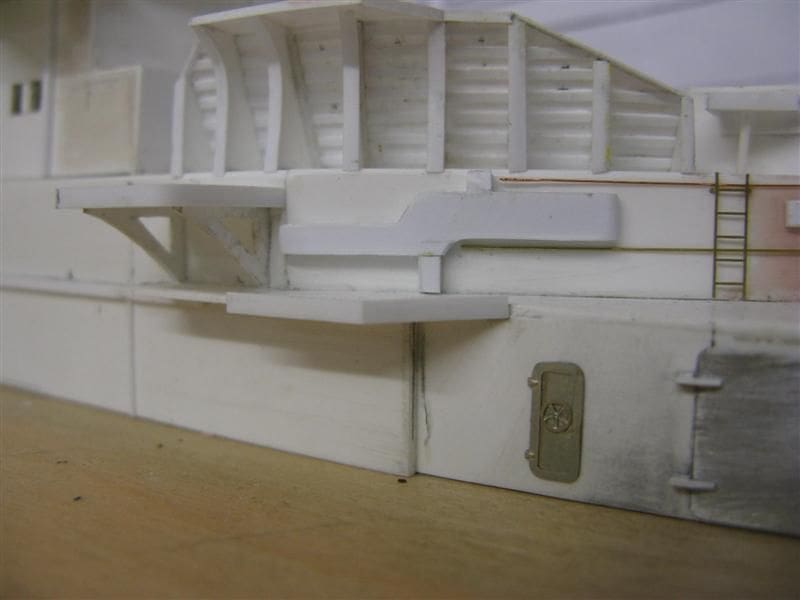
Deck housing and preparation for glazing
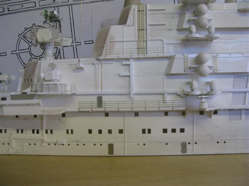
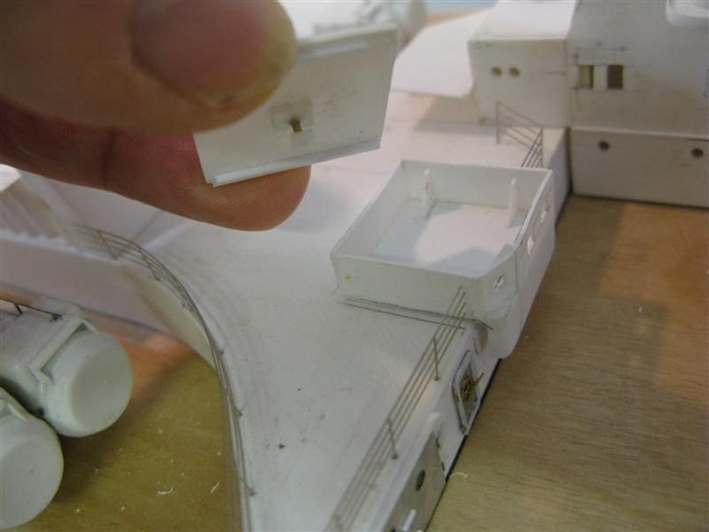
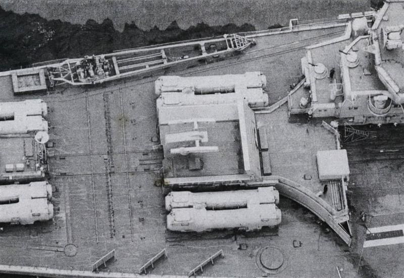
Just abaft of the SA-N-7 launcher blast screen is sited a small deck housing, the purpose is unknown, but there are a series of windows on the section facing the flight deck. These will need to be glazed at some future date after everything has been painted. To facilitate this, the roof is made detachable and in the centre of the roof is a detachable aerial. Once again the purpose for this is to ensure that the aerial, which will be painted a dark shade of grey can be removed, painted and then reinserted into the centre of the roof, Photo 32. It is important where possible to paint separately as many fittings as possible. The relative position of the deck housing can be seen in this aerial picture of Kiev taken some time in the 1980s Photo 33.
Answer to the November Mystery Picture
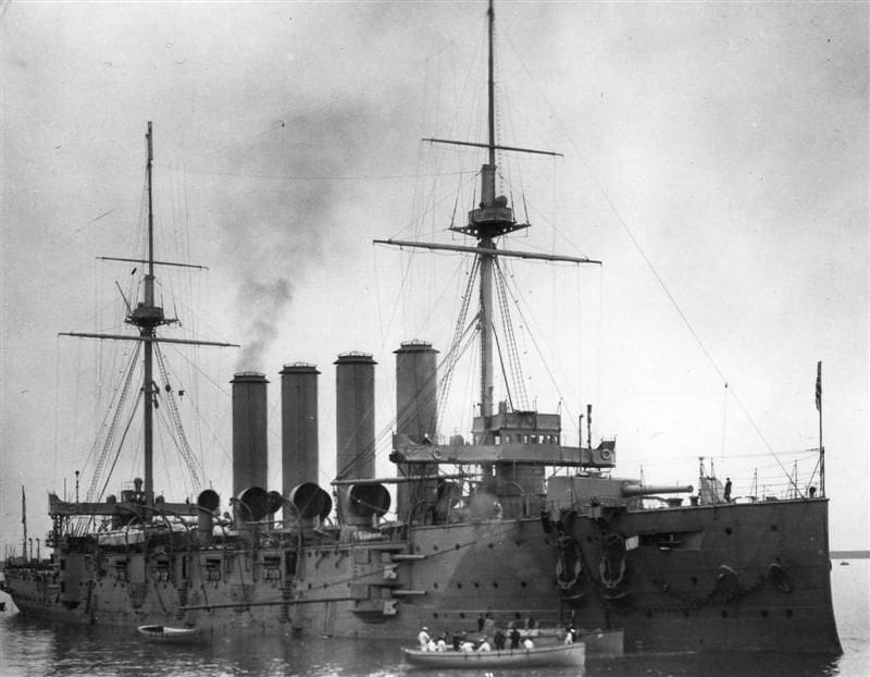
This was CL7 USS Raleigh. Ships of the US Navy always seem to generate interest, but this particular vessel as shown last month was unusual indeed and on a scale of 1-10 for difficulty is number 9.
Raleigh formed part of the ten ship Omaha Class and the first of the class, CL4 USS Omaha was laid down on the 6th December 1918, almost a month after the armistice that brought WW1 to an end. Built at Bethlehem Quincy, USS Raleigh entered service with the USN in February 1924. Being driven by Curtis geared turbines with four propshafts, meant that USS Raleigh with a top speed of 34kts was an impressively fast light cruiser. She was faster than the British post-WW1 E Class which were laid down at the same time as the Omaha Class, but entered service nearly two years later. In the same decade Japan was commissioning the Kuma Class of fast light cruisers capable of 36kts, but they lacked the firepower and armour protection of the Omaha Class.
Raleigh was fitted with 12 boilers separated into four boiler rooms, two forward and two aft, hence the distinctive funnel arrangement which made for a rather dated appearance. Although having a total of 12 x 6 inch, one twin turret was forward and one right aft, with the remainder of the 6 inch guns disposed in casemates well above the waterline. As the excellent photo showed, the forward four were arranged, two on each side in front of the bridge with one above the other. This was not so much a departure from accepted cruiser design, as revisiting the past.
Raleigh was also equipped with two catapults abaft the fourth funnel. Like the British E Class cruisers, the displacement at full load was about the same. HMS Emerald displaced 9436 tons whilst the USS Raleigh displaced 9296 tons. These similarities also extended to the degree of armour protection.
USS Raleigh was a casualty of the Japanese carrier strike on Pearl Harbour, but the bomb damage was repaired and she was to see action again serving with distinction in the Aleutian and Kurile Island campaigns in the North West Pacific. By VJ day in August1945, Raleigh had fought and survived in the Pacific theatre, but she was stricken from the Navy List in late 1945.
As a footnote to the development of cruiser design for the US Navy, the Department of War had in place well before WW1, a system of naval war plans under the general heading of Rainbow Plans. These were designed to accommodate various scenarios where the US Navy would need to be deployed . For example Plan Rainbow 6 (Orange) was for operations against Imperial Japan, Plan Rainbow 1 (Black) against Imperial Germany and Plan Rainbow 5 (Red) was, yes against Great Britain!
This months Mystery Picture
The clue is Three before breakfast, Photo 35.
References and acknowledgements
The INS Mumbai ref: Janes Fighting Ships 2008. Combat Fleets of the World 15th edition. Naval World Weapons Systems 2008. Indias Twelve Steps to a World Class Navy by Dr Thomas PM Barnett. Sea Power and Indian Security by Rahul Roy-Chaudhury.
USS Raleigh ref: US Warships of WW2 by Paul H Silverstone. Cruisers of World War Two by MJ Whitley.
War Plan Orange by Edward D Miller, ref; Naval War Plans USN.
Bill Clarke Researcher USA, re.photo of USS Raleigh (National Archive USA).

