DAVE WOOLEY with his World Wide Review of Warships and Warship Modelling
Welcome once again to our regular sortie into the world of fighting ships. This month we are having a look at some of the exhibits on offer at the National Cold War Exhibition. We also examine a 1:72 scale INS Mumbai destroyer built by Task Force 72 member Alan Pew and there is Part Three of our HMS Daring construction project.
Enjoy more Model Boats Magazine reading.
Click here to subscribe & save.
Cold War Exhibition
In April 2011, together with Bill Clarke my colleague and friend from the USA, I attended the annual model show at RAF Cosford. The RAF Museum here houses one of the largest collections of RAF aircraft in the UK, plus a large and varied number of guided missile exhibits, from WW2 through to modern times. The model show is essentially an International Plastic Modellers Society (IPMS) UK event with some marine and trade input. However, the prime reason for the visit was (and is) my interest in the Cold War Exhibition which is the largest of its kind in Europe.
This exhibition, contains some of the most iconic aircraft of the Cold War period, from both NATO and the Warsaw Pact. Accompanying the aircraft is a range of displays including armoured vehicles, helicopters and missiles, all arranged in such a way as to take the viewer on an audio-visual journey through those years. The exhibition is cleverly assembled so as to allow you to relive some of those epoch making moments that occurred during the Cold War; for example the chilling days of the Cuban Missile Crisis in 1962 when the world came close to an all out nuclear exchange between the superpowers, but here I am just concentrating on the naval elements of the Cold War.
The ultimate naval weapon?
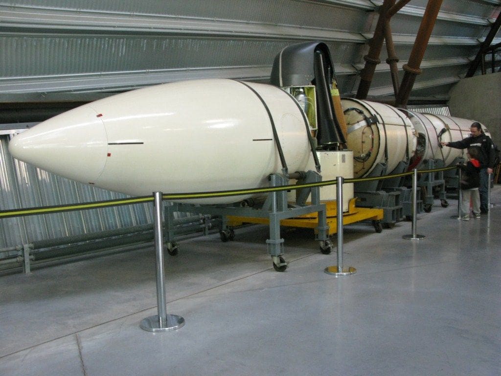
As the Cold War now moves into history, guided weapons of the period, both nuclear and conventional, are now becoming available to view. One of the most devastating weapons of that period was the submarine launched Polaris missile. Initially it was designed in the early 1960’s for the USN Lafayette class of submarine, but after the Nassau Conference of 1962 it was decided to move the UK primary deterrent from the V-Bomber force to the British built Resolution class of SSBN’s. These deployed 16 of the USN Polaris A-3 nuclear armed missiles. The missile’s capability was a closely guarded secret, but later it is was upgraded to carry the AT-3K warhead, better known as Project Chevaline. This was an all British multiple targeting system or MRV’s (Multiple Re-Entry Vehicles), each capable of delivering three warheads to three different targets, Photo 1.
Ikara
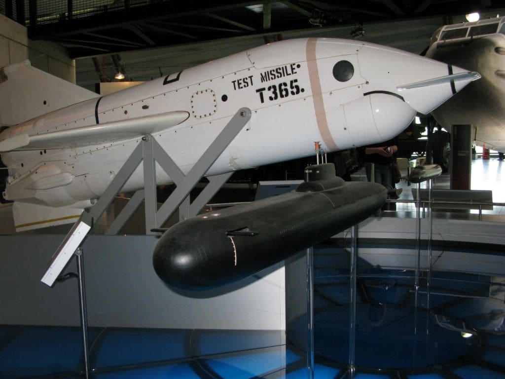
In order to combat both nuclear and conventional submarines, Australia and the UK embarked on a collaborative anti-submarine warfare project to produce a rocket launched torpedo system which was called Ikara. Initial development was in the late-1950’s.
Basically, this rocket assisted torpedo launch system was a radio commanded powered glider carrying a lightweight torpedo to the approximate position of the target submarine.
The Mk. 46 homing torpedo was then detached from the rocket assisted glider, whilst deploying two small fins to aid its gliding stability into the sea. Once in the water, the torpedo would undertake a search pattern for the target whilst the rocket propelled glider would enter the water well away from the torpedo to avoid any possible interference with the attack. HMS Bristol and Batch One RN Leander class frigates were fitted with the system. The intention was that the system would always be at instant readiness, but it turned out to be temperamental and suffered from maintenance and loading problems, Photo 2.
Sea Skua
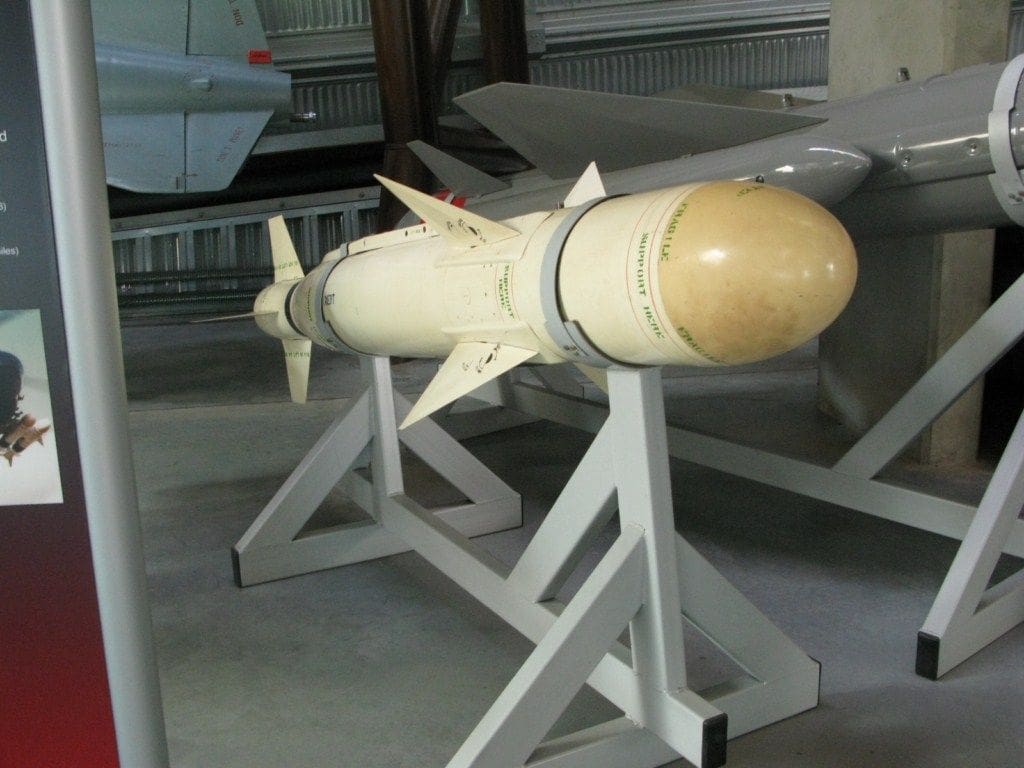
This type of missile was primarily designed as a helicopter launched anti-ship missile which provided frigates and destroyers with the ability to strike targets such as fast patrol craft at a distance from the parent ship and also allow the helicopter to maintain a safe firing range, clear of any anti-air defences on the target vessel. Guidance was through semi-active radar whilst Seaspray radar and ESM (Electronic Support Measures) aboard the helicopters (usually a Lynx) would locate and identify the target, Photo 3.
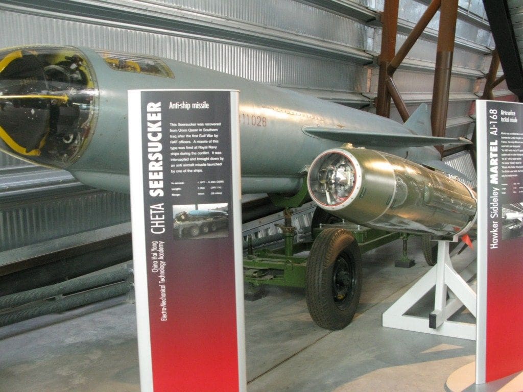
HY-2 Seersucker anti-ship missile
This particular missile, Photo 4, was recovered after the first Gulf War of 1992 and it is a slightly longer version of the Chinese manufactured HY-1 Silkworm anti-ship weapon. ‘HY’ stands for Hay Ying (Sea Eagle) and it is a Chinese copy of the Soviet SS-N-2 Styx missile. This missile came to prominence in 1967 with the sinking of Eilat, the Israeli destroyer, by an Egyptian Komar class boat so armed.
The HY-2 Seersucker, although a copy of the Styx, had its warhead weight reduced to 513kgs to improve the range of the missile to 95km. It was powered by a combination of a turbo-jet power plant and a solid fuel rocket booster for launching. Guidance was inertial with active conical scanning with terminal guidance infra red technology and radar. Compared to the present generation of surface to surface missiles, it is a cumbersome piece of equipment and can be defeated without too much of a problem. However, the cruising speed is just below Mach One and a direct hit from such a large missile would still inflict considerable damage.
Ballistic Missiles
Anyone with an interest in this period and its hardware will not fail to be impressed by the Sky Bolt stand-off nuclear tipped missile in the bomb bay of a Vulcan bomber or the land based Thor Intermediate Range Ballistic Missile (IRBM) of which 60 were deployed in the UK between 1959 and 1963. If like me you have more than a passing interest in missile technology then RAF Cosford also has a collection of early anti-ship guided bombs and missiles, deployed towards the end of WW2 and immediately afterwards.
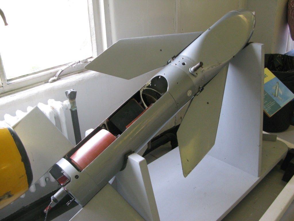
Sea Cat point defence weapon
In the Test Flight Centre there are a number of interesting exhibits including a cut-away Sea Cat missile, Photo 5, that was installed on many UK warships during the Cold War. Measuring 147cm long x 19cm diameter, it was normally installed on a quadruple launcher. The solid propellant rocket would be guided to target by command line of sight. Using a thumb operated joystick (a bit like an r/c transmitter) and a pair of binoculars(!) in a Mk. 20 guided weapons director unit, the operator would attempt to hit the target. Maximum range was approx. 5km up to a height of 1000 metres although the effective range was actually less.
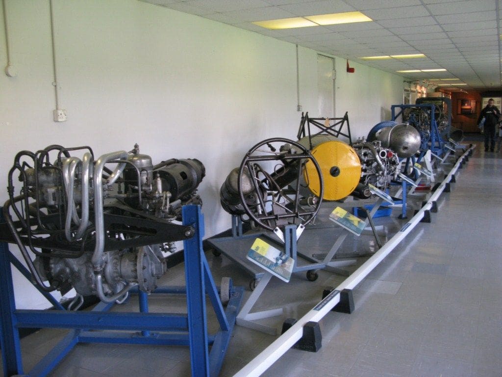
There is also a really interesting collection of late-WW2 missiles and the novel rocket motors that powered them, Photo 6.
Model displays
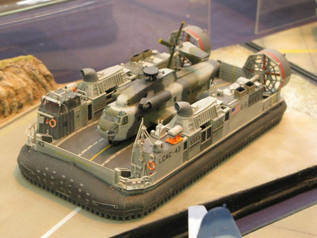
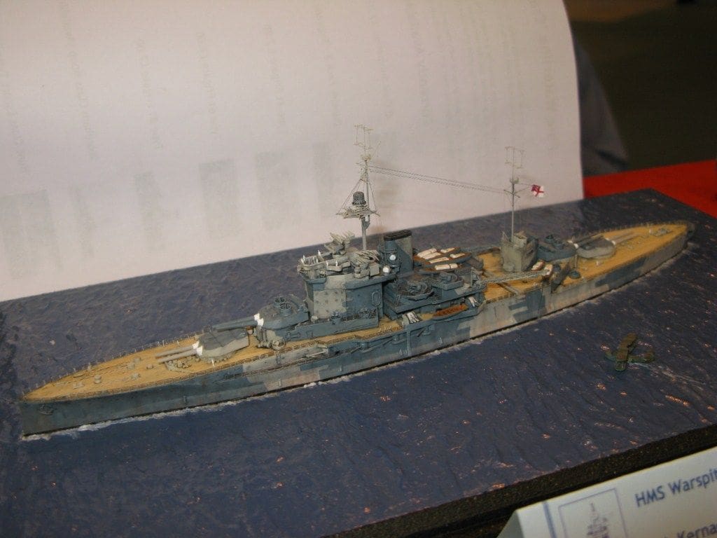
The visit coincided with the IPMS event and there a superb display of both aviation and marine subjects within that show. Although usually to a small scale, the workmanship and effort that is lavished on these models is a treat to see. An example was this 1:350 scale LCAC complete with helicopter, Photo 7, and Photo 8 is of a 1:700 scale HMS Warspite built by Rob Kernaghan.
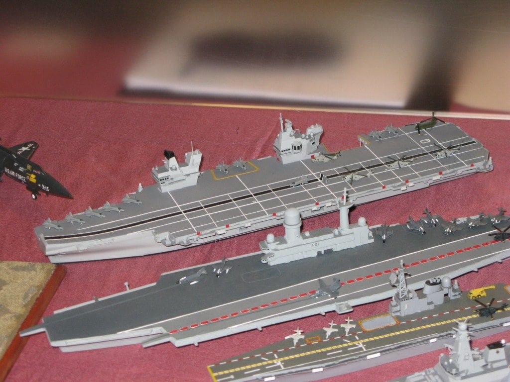
One particular collection, Photo 9, that caught my eye, included a model of the new RN aircraft carrier HMS Queen Elizabeth. Next to it and to the same scale of 1:700 was the cancelled RN fleet carrier of 1966, CVA-01.Even by today’s standards the CVA-01 looked futuristic in design and would make an interesting large scale working model. Of course following the strategic review of late-2010, the new RN aircraft carrier is being reconfigured with a totally flat flight deck with ‘cats and traps’ rather with a ski-jump as sadly the Harriers are no more and the government have now selected the conventional version of the F35 Lightning instead of the vertical and STOL variant.
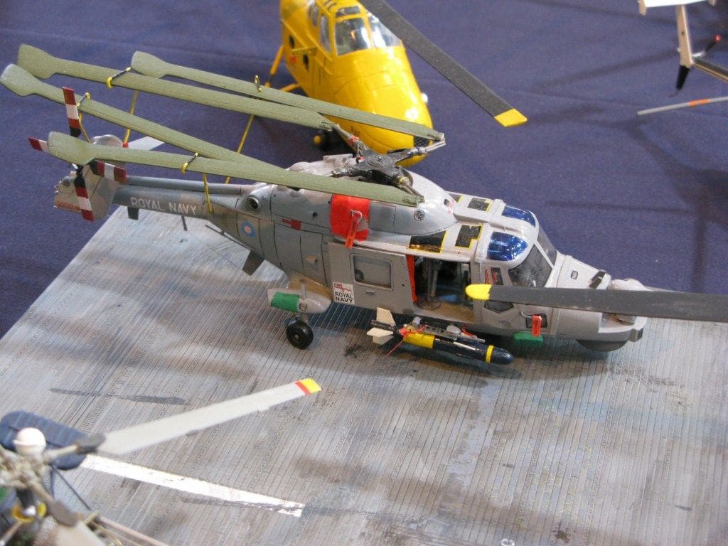
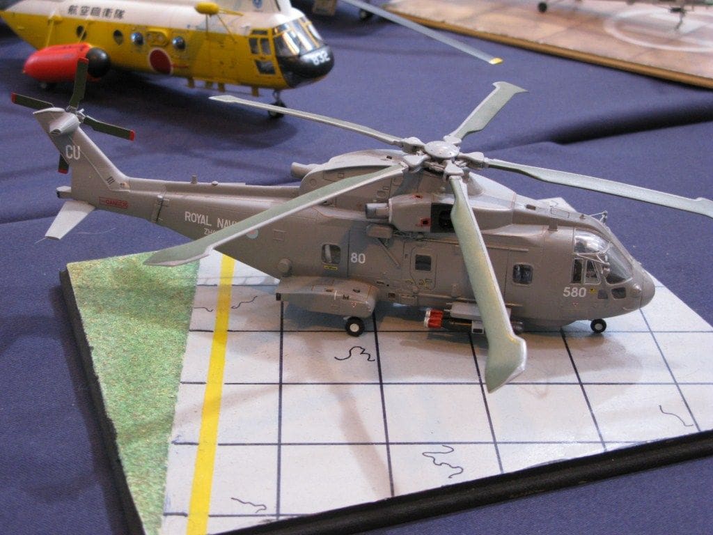
I was not disappointed with these examples of a Lynx HMA.8, Photo 10, and a EH101 Merlin HM Mark1, Photo 11. These are aircraft flown from current UK warships and would look great on any model flight deck.
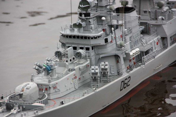
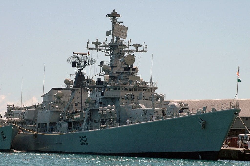
INS Mumbai D62
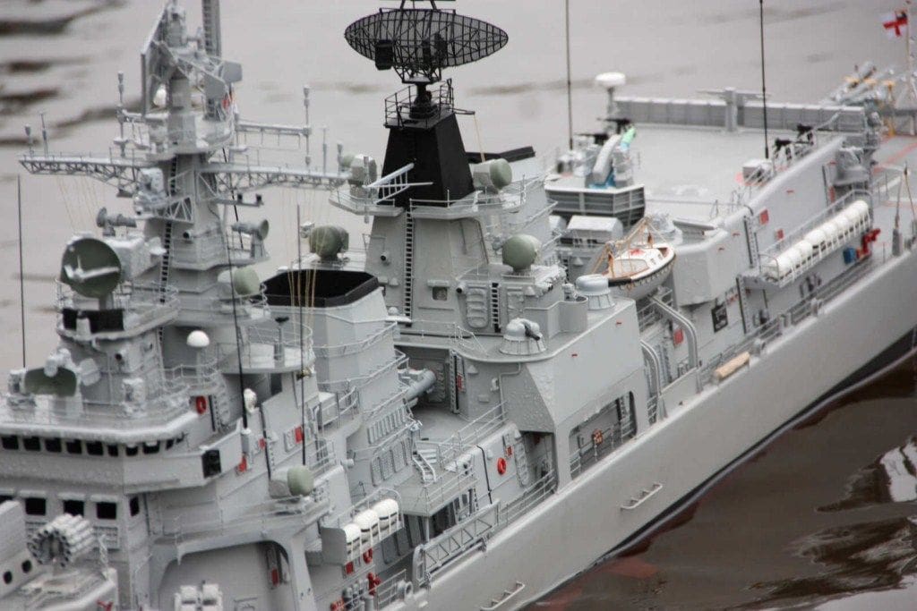
She is the third of the Delhi class guided-missile destroyers and is in current active service with the Indian Navy, Photo 12. The model of this Indian Navy guided missile destroyer is to a scale of 1:72 and has been built by Alan Pew of Task Force 72, an Australian model warship association. Alan is also currently vice-president of Task Force 72 and these pictures have been supplied by Michael Brown. Alan, has of course for many years produced hulls and fittings of warships to the common scale of 1:72, which is very popular in Australia.
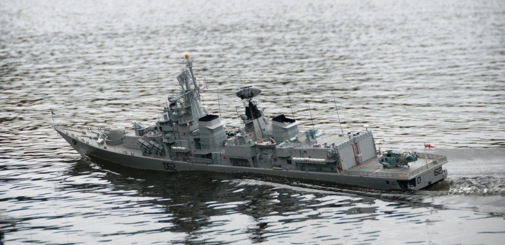
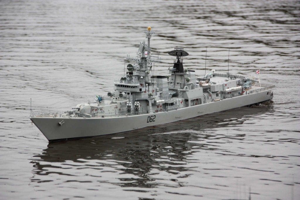
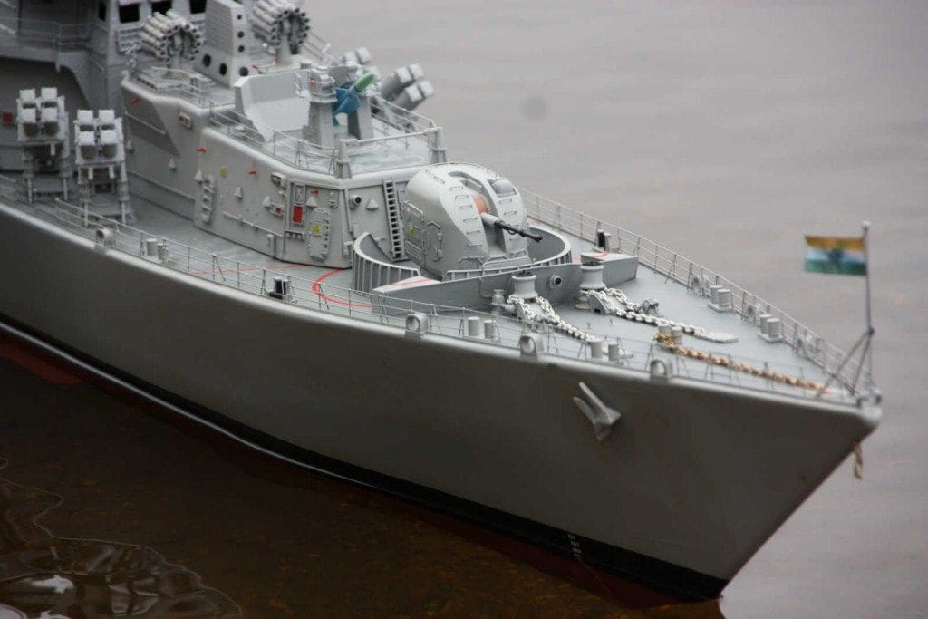
His model, Photos 13 and 14, is based on drawings produced by himself supported by numerous photographs. Alan used a Sovremenniy class (a Russian destroyer) hull as a basis for the model of Mumbai, but had to extensively re-work it to match the Indian Navy warship. He then created a new mould from the reworked hull. A large number of the fittings on INS Mumbai are of Russian origin including the two MS196 launchers for the SA-N-7 missile system, the 100mm/59 calibre gun and AK630M close in weapon system. Others such as the two 12 round RBU6000 ASW rocket launchers forward of the bridge and many of the search and tracking radars are also of Russian origin. All of these fittings are produced by Alan in 1:72 scale for other Russian warship model types, so were very suitable for this model.
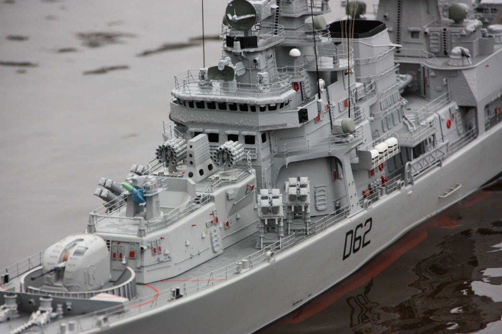
Anyway, the net result is a truly superb example of the model maker’s art, Photos 15,16 and 17, that looks authentic in and out of the water, but is absolutely stunning when compared to a photo of the full size ship.
1:72 scale HMS Daring Type 45 destroyer – Part Three
Moving on from the last issue, the next step involves fitting the decks. Although the flight deck and forecastle deck are available from Fleetscale as GRP mouldings, my personal preference is marine ply, as cutting into timber for interior access is relatively easy and as the middle section 01 deck is of marine ply anyway, I have kept all the decks of the same material. However regardless of which material is used, and I would not recommend styrene for such large flat surfaces, the fitting process is the same and only the type of adhesive might need to be amended.
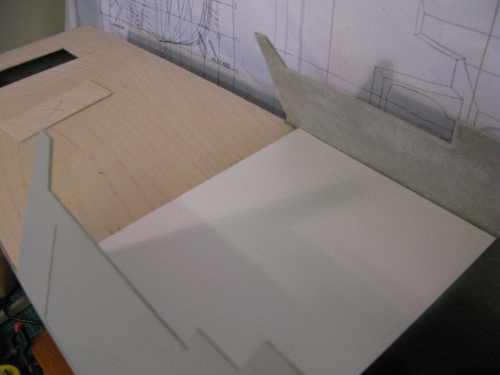
Flight deck
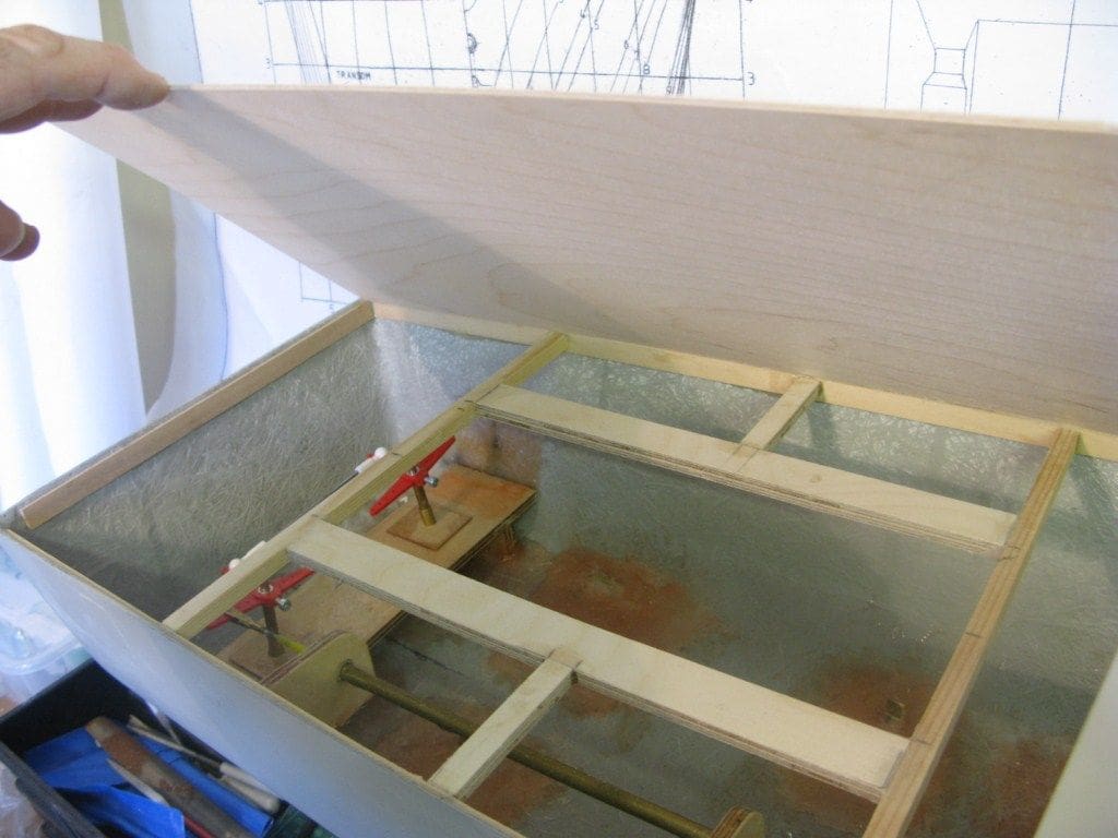
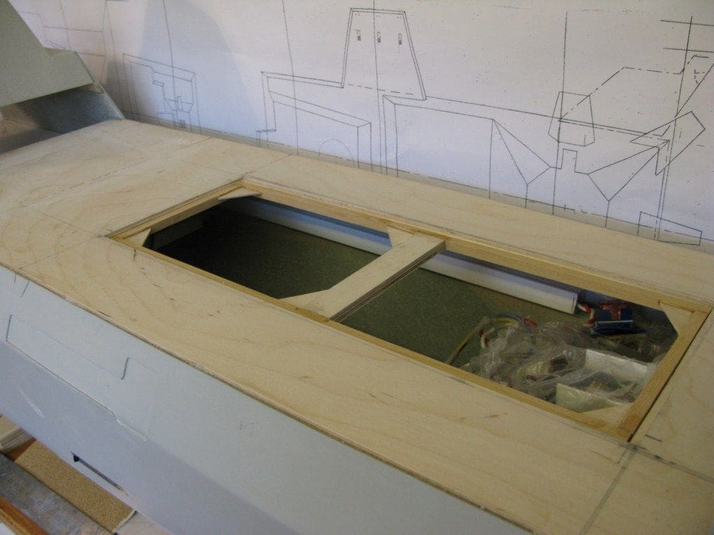
With this cut to overall size, there are a number of options available for providing access to the tops of the rudder posts and their linkages, Photo 18. Okay, you could install everything and seal it all in and hope for the best, but I guarantee that sooner or later access will be required. In the end, a small section above the rudder posts was cut away for a flush hatch to fitted, but it occurred to me later that the flight deck landing circle could also be cut out, such that the join would be the edge of the circle and thus hard to see. Hindsight is a wonderful thing!
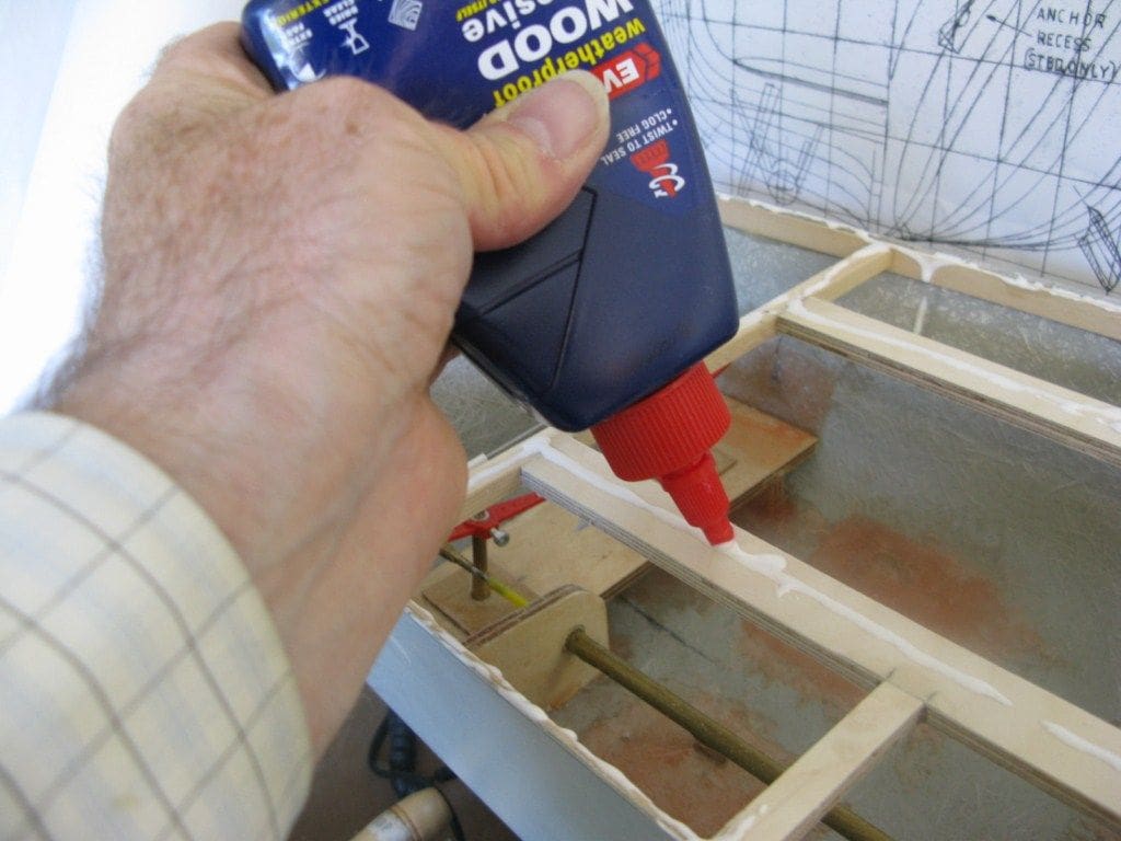
A good quality waterproof wood adhesive is applied along the length of each support beam ready for the deck to be slotted into place. It was held firmly in position whilst the adhesive set with masking tape across the flight deck from one side of the hull to the other and several weights distributed around it, Photo 19.
Hangar space
With the flight deck in place, attention shifted to preparing the hangar floor initially and later, the rigid inflatable boat (RIB) recesses either side of it. The actual openings in the sides of the hull for the RIB recesses will be cut later when the bulkheads are installed. The internal hangar deck is of styrene as will be the dividing bulkheads, all of which makes for ease of construction and finishing, Photo 20.
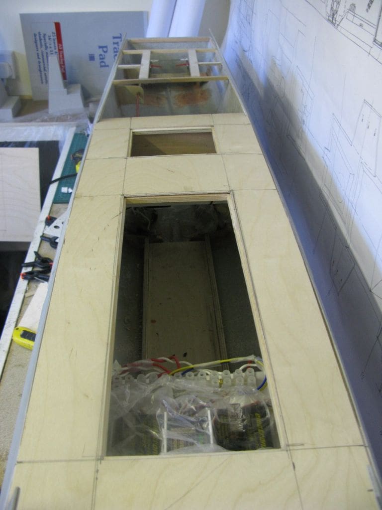
01 deck
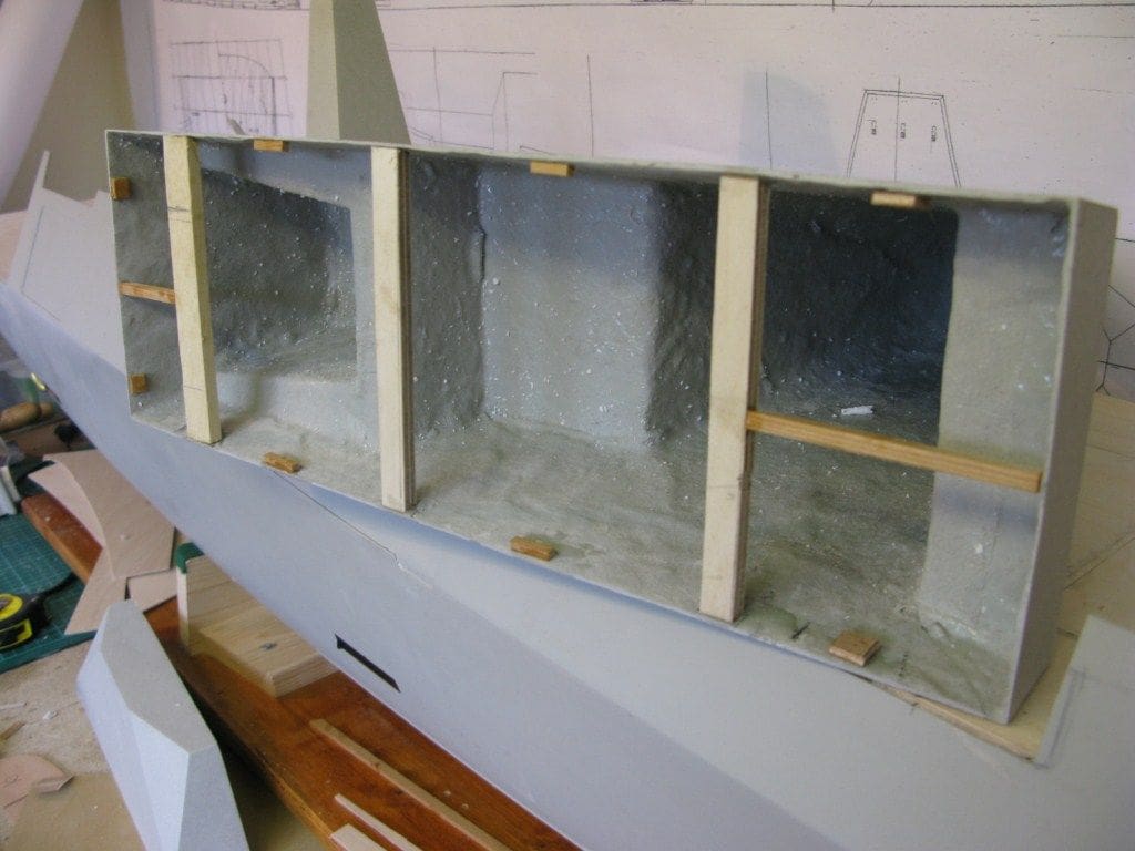
This deck, which will support the main upper body of the superstructure, is cut to size and the openings immediately below the forward Sampson mast and superstructure and the communications mast are cut away, as in Photo 21 (Please note that this work was done at the same time as the flight deck work for convenience). Frameworks were made to fit into these openings and Photo 22 is of that beneath the communications and ESM mast.
Eventually the superstructure units immediately above these openings will be fixed to and over the inserts. The purpose of all this is to minimise as much as possible any evidence of cuts into this deck because they are hidden just underneath the edges of the units above them.
Forecastle
Broadly speaking, this is flat. Checking where the deck meets the forward edge of the VLS housing and then the lower front face of the bridge confirms that in those locations it is indeed flat. So, following the same procedure to that of the flight deck, and over the frames underneath, Photo 23, the forecastle deck is slotted comfortably into place, Photo 24. On this model no openings into this forward section of deck were required
01 deck forward superstructure unit
Back on the central 01 deck, Photo 25 shows the framework within the larger of the two access openings. You will also notice (just!) that the wooden deck edge is fractionally above the inside of the top edge of the GRP hull. The reason for this is that the ledge created will provide some support for the bulwark to be fitted later.
The GRP superstructure unit that fits on top 01 deck is well made, but the bottom edges that are to sit on the deck although perfectly straight bow to stern and across the beam, actually curve slightly (‘undulate’ might describe it better) in and out. This is not unusual as GRP prefers to be curved rather than perfectly flat.
Remedying this is what model making is all about and is easy to rectify and in any case, some internal bracing will be required anyway. So, bracings and fixing points were fitted into the underside of the moulding, Photo 26. This was followed by marking out a timber base and fixing that into the GRP moulding forcing any concave sides straight, Photo 27, and pulling in any convex sections.
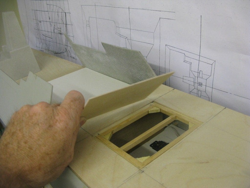
Bridge and main superstructure front
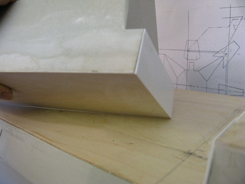
Building this, with its angular construction was not that straightforward. The plan was for the one piece moulded front section to slot between the sloping sides. After rubbing down the interior of the hull sides, the front section did indeed fit into place quite well and my first thought was to slot the main superstructure into this front section, which would have required the top part of this GRP moulding to be removed as in Photo 28. Unfortunately I realised just too late that due to the slopping sides of the hull upperworks, it would not lift clear. The only option was to remove a small section of the main superstructure forward. Enough was retained so the bridge unit can now rest in its intended location immediately forward of the Sampson mast, so the superstructure will now lift clear and fit neatly into the rear of the bridge front panel.
A new top had to be added to the lower front section, but in so doing, an irksome problem was solved, Photo 29 (this viewing from the starboard side).
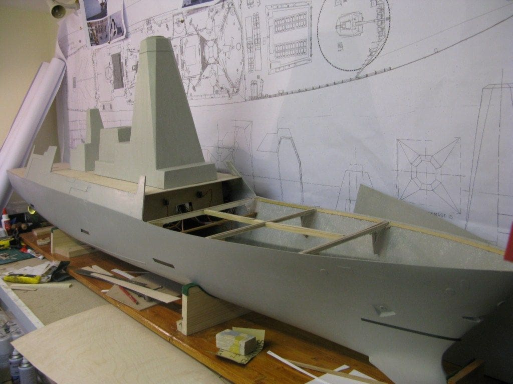
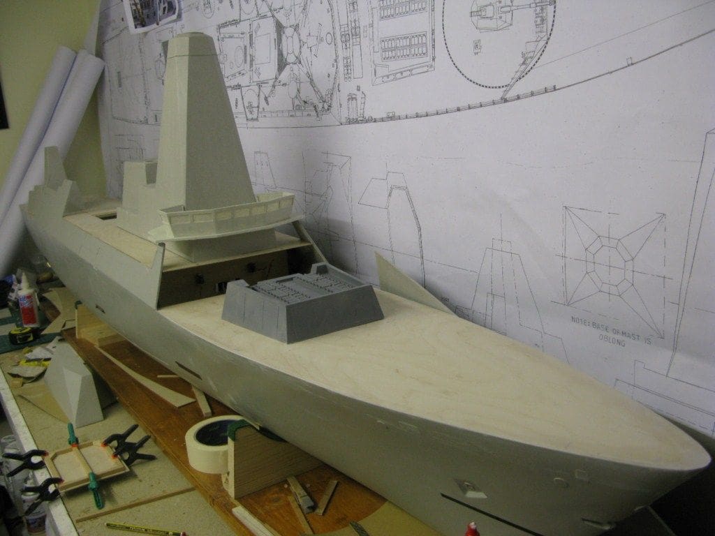
Photo 30 shows how it should all eventually look and Photo 31 shows progress on the model thus far. As you can see, the superstructure unit with the Sampson mast also includes the funnel.
After radar mast
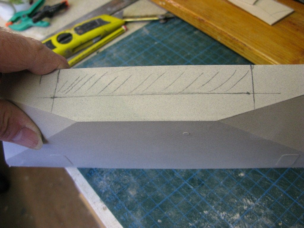
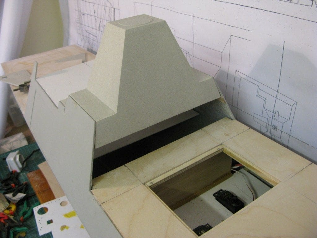
This supports the Signaal/Marconi Type 1046 air and surface search radar and the moulded unit should slot into place between the slopping sides above and at the front of hangar. A little bit of sanding, and no more, was all that was needed, Photo 32, but there was a snag looming which was nil access to the motors and their propshaft couplings! The only answer was to replace the moulding with a built-up structure that could be separated and allow direct access to the motor couplings.
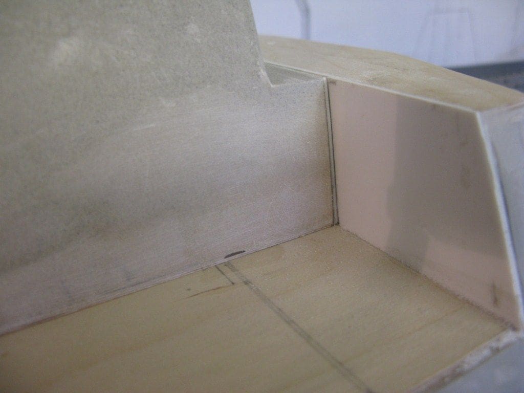
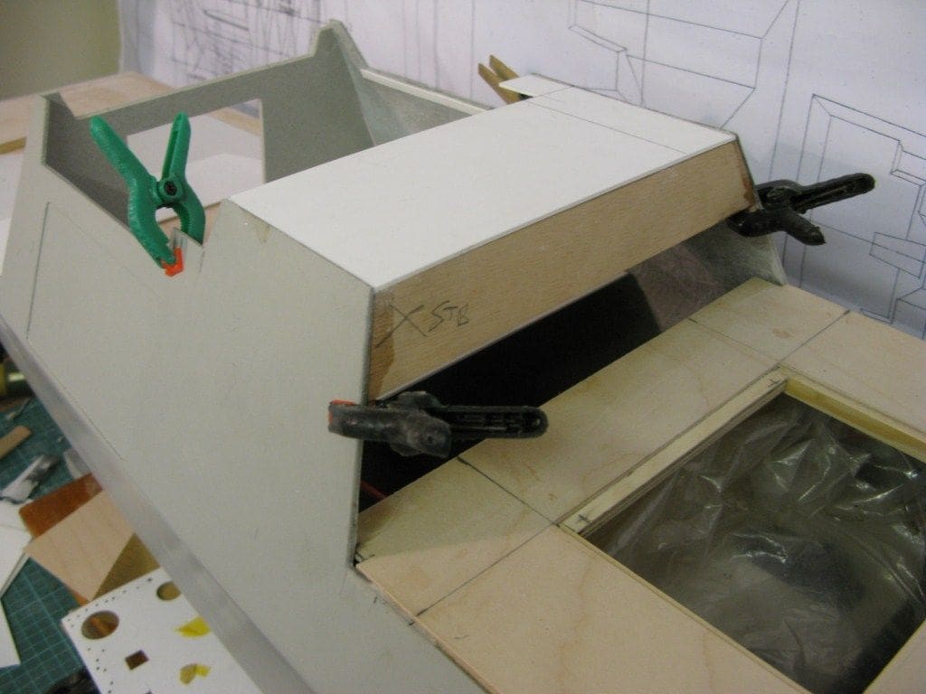
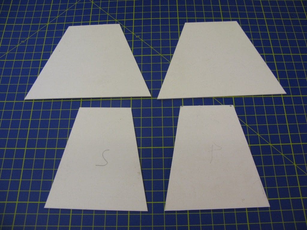
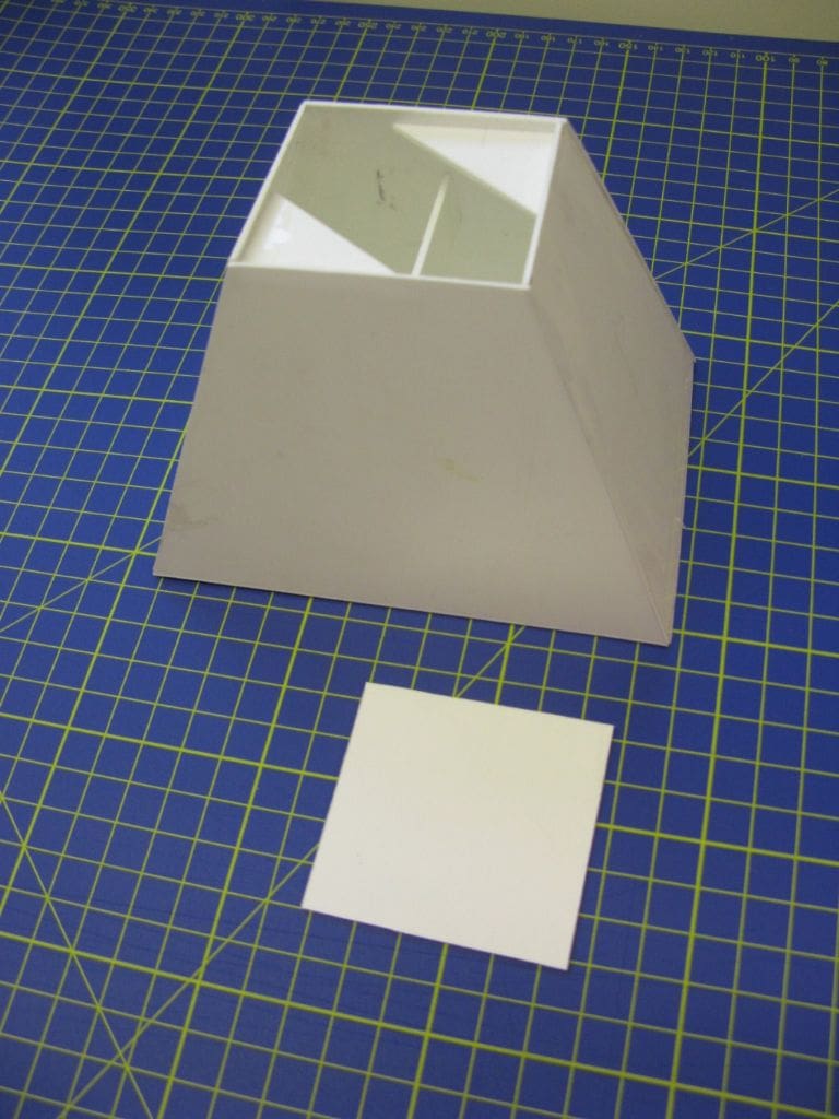
So, the front and rear sections were cut to size from 2mm marine ply and these provided a suitable surface for the base of the pyramid type of mast, Photo 33. An access opening was then cut into the styrene top which was slightly less in area than the base of the pyramid mast, Photo 34, and a styrene front panel was also added, Photo 35.
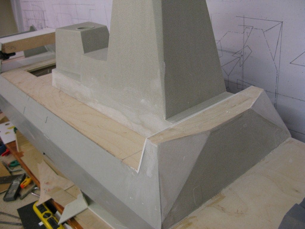
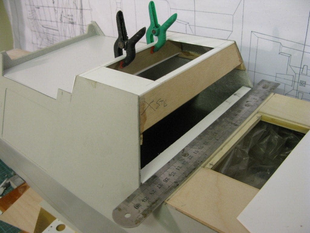
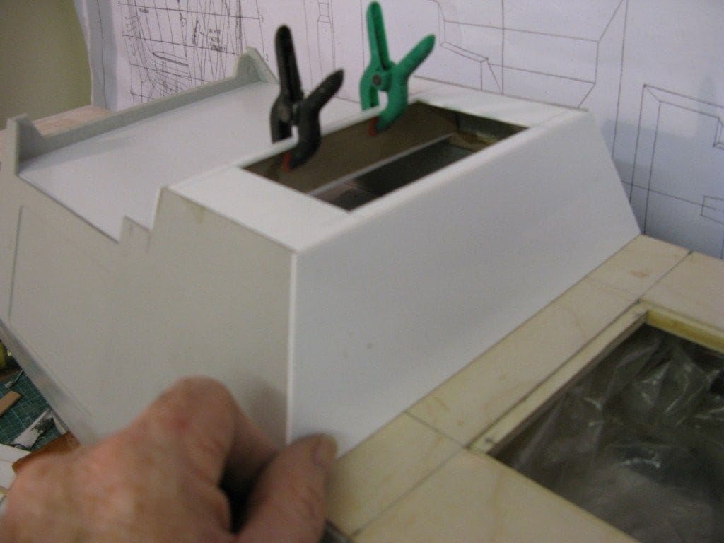
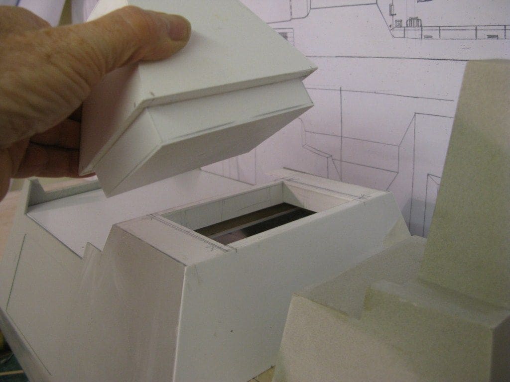
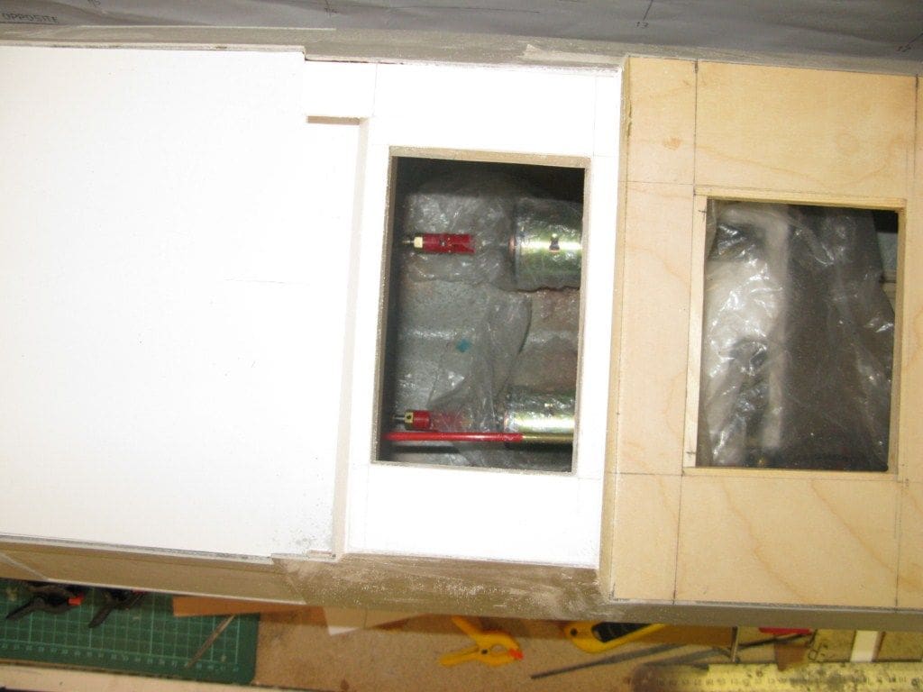
The pyramidal type shape of the mast was taken from the Jecobin drawing starting with both port and starboard, then fore and aft faces, allowing for the thickness of the styrene, Photo 36. Each side was then fitted to the outer edges of the base which had been cut to size allowing for the thickness of the side pieces, Photo 37 (please note the internal bracing). A styrene box section was created underneath so as to ‘plug’ into the hole in the lower section. So now, the mast unit could be easily removed allowing access with a long screwdriver to the motor couplings etc., Photo 38 and Photo 39 is a vertical view into the abyss below! Next month we are having a go at the internal hangar void and adjacent RIB recesses.
Answer to last month’s Mystery Picture
This was USS Lester, DE 1022.
The great challenge in the post-WW2 era was militarily to offset the huge increase in Soviet submarine production. The lessons of ASW in WW2 were still being digested in the early 1950’s, but the basic fact was that Nato did not have enough escorts with an anti-submarine capability to provide adequate convoy protection should the Cold War turn hot!
The Soviet navy was building a fleet of ocean going submarines based in part on captured German technology relating to the Type XXI boat that had been deployed in the closing stages of WW2 by the German Navy. These had high underwater speed and the ability to remain submerged for a maximum of 166 hours (a week), and this meant that they were a significant threat to the allies in WW2, but by then the war was lost for Germany. However, the Soviet navy now designed and built no less than 235 boats of the Whisky class which could possibly achieve what the Kriegsmarine were unable to do and force the Western Alliance out of the Atlantic.
Therefore, the most pressing need was to expand the building programs for ASW escorts, which the US Navy referred to as ‘destroyer escorts’. The USS Lester was laid down in September 1954 at the Defoe Bay City Shipyard and was part of the construction programme designed to deal with this growing Soviet submarine threat.
Reflecting the wartime experiences of the Dealey class, USS Lester was designed from the onset for mass production. She displaced just 1877 tons in a hull 96m long by 11.2m beam. For anti-submarine warfare, USS Lester was fitted with the SQS-4 sonar and RUR-4 Weapon Alfa, an ASW rocket launcher forward of the bridge. She was also armed with four 3 inch /50 calibre guns mounted fore and aft.
There was just a single propshaft, reflecting the capability for mass production, and a steam powered geared turbine. Top speed was a very respectable 27kts with a range of 6000nm at 12kts. Later in the 1960’s. most of the class had their after 3 inch guns removed and replaced by a flight deck and hangar for a DASH (Drone Anti-Submarine Helicopter). This was designed to deliver both conventional and nuclear torpedoes and was considered to be a practical alternative to the ASROC (Anti-Submarine Rocket) system.
The drone helicopters were not successful, but recently drone aircraft have come into their own and are used extensively for reconnaissance and target acquisition. USS Lester was sold for scrap in December of 1973.
There is insufficient space for a Mystery Picture and clue this month.
Reference and acknowledgements
Cold War missiles ref: The Naval Institute guide to World Naval Weapons Systems 1989 edition; Polaris Page 40; Ikara page 410; Silkworm /Seersucker page 79.
Sea Cat ref: Naval Surface Weapons by Dr. D.G. Kiel, pages 77 to 84.
USS Lester ref: Conway’s All the World’s World Fighting Ships 1947 to 1995, page 595.
The Worlds Warships by Raymond V.B. Blackman, page 149.
Ikara and DASH helicopters ref: Modern Warships by Norman Friedman, pages 130 to 135.
My thanks to Bill Clarke for contributing the picture of the USS Lester.
Michael Brown for photos of INS Mumbai model.
For those wishing to build HMS Daring, please contact Fleetscale, website:
www.fleetscale.co.uk

