DAVE BRUMSTEAD with a current summary
General development since the 1940
Since the last war, radio control equipment has developed at much the same rate as the domestic electronics market. No longer do we have to carry bulky transmitters with eight foot long aerials to the pond side, accompanied by large dry cells. Installation of equipment in our models is also much simplified by the current small size of radio receivers, battery packs and servos.
Enjoy more Model Boats Magazine reading.
Click here to subscribe & save.
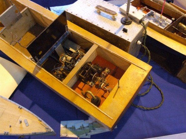
A typical set up in the 1950’s consisted of a ground based transmitter with a cable connected hand set. Inside the model boat would be a receiver and rudder actuator (a forerunner to the modern servo), Photo 1. From the late 1960’s the range and style of transmitters evolved to what we use now. Although the MacGregor style of single channel transmitter (widely used by model boaters at that time) was smaller than more modern two or four/six channel versions, it was operated by a single push button and had just one function. This control would send a signal to the receiver, which depending on what type of actuator (servo) was fitted, would give left rudder, centre, right rudder, centre, etc., a much reduced functionality to that which we are used to today.
Modern radio is described as having proportional control, in that if the control lever is moved through 50% of its travel, the corresponding function controlled by the receiver would move the same amount, e.g. half throw on the rudder or half motor speed.
Transmitters
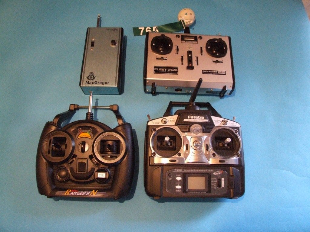
Although styled in the 1980’s, the Fleet transmitter (sadly now discontinued) uses the 40MHz frequency, which may be altered by changing the transmitter and receiver crystals. A more up to date design from Hitec, transmits on 27MHz, again frequency controlled by crystals. Finally, the latest innovation in radio control is the 2.4GHz set. These sets are able to lock on to, or in the case of a Futaba set, ‘hop across’ eighty available frequencies in the 2.4GHz range. No crystal is required in either the transmitter or receiver. These sets are becoming extremely popular because of their user convenience and low prices, which certainly for model boat users, are very competitive. Photo 2 shows these different types of transmitter including a MacGregor single channel from the late 1960’s in the top left. Most modern transmitters fit into the hands comfortably, although some specialist aircraft and helicopter types are designed to be used fitted within a tray. I should add that there are many brands of r/c equipment. A look at the advertisements in any issue of MB, or any r/c model magazine, will reveal the huge range mow available to us.
Receivers
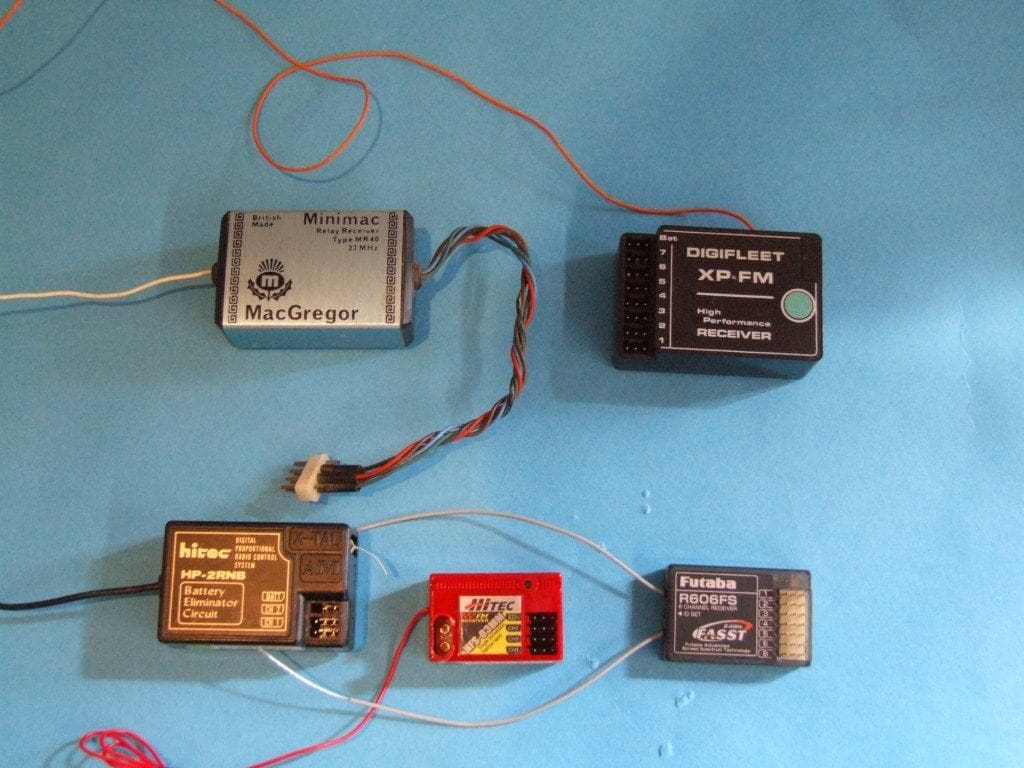
These have also evolved over recent years, with their capabilities corresponding to those of the transmitters. Thus in the time of single channel, that is exactly what the receiver was capable of handling. If the transmitter can broadcast on seven channels, then an equivalent receiver is required. The size of receivers has also changed with the use of modern manufacturing technology. This has evolved from the MacGregor type which was quite large to the modern small multi-channel 2.4GHz receivers, Photo 3. Notably, 2.4GHz technology uses a much shorter aerial(s) compared to 27 and 40MHz, but the 2.4GHz signal will not penetrate water, so if you wish to operate r/c diving submarines, please use 27 or 40MHz!
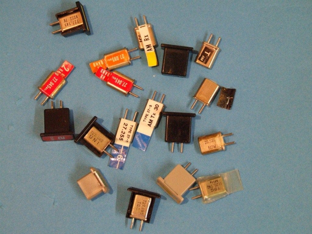
These last two frequency bands, use crystals for frequency control. If using these sets it is wise to have a selection of crystals to increase sailing opportunities when others are on the water. To prevent interfering with or receiving interference from other models, each radio control set in use must operate on a separate frequency. This is achieved in the 27MHz range by interchangeable crystals normally described by their colour, whereas 40MHz systems use numbered crystals e.g. 40.665, 40.895, 40.805 etc. Each is also marked Tx (Transmitter) or Rx (Receiver), Photo 4, and are not interchangeable. As an addendum here, some 40MHz equipment was manufactured in recent years with a ‘Synthesiser’ capability. This meant that the frequency could be ‘dialled’ into the transmitter and receiver , thus negating the need for Xtals. However now (in the UK certainly), the advent of 2.4GHz has negated the need for xtals completely.
So, we are now at the stage where we can transmit and receive a signal. The next stage is to convert this into useful mechanical action. The most common device for this is a servo, previously known as an actuator.
Servos
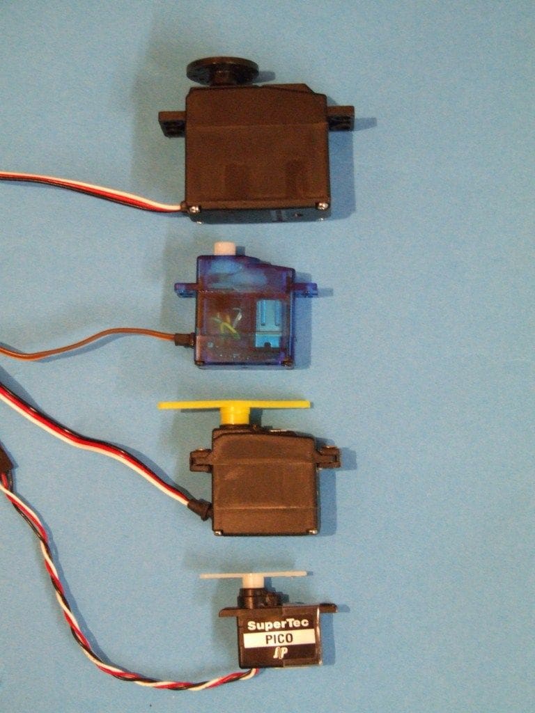
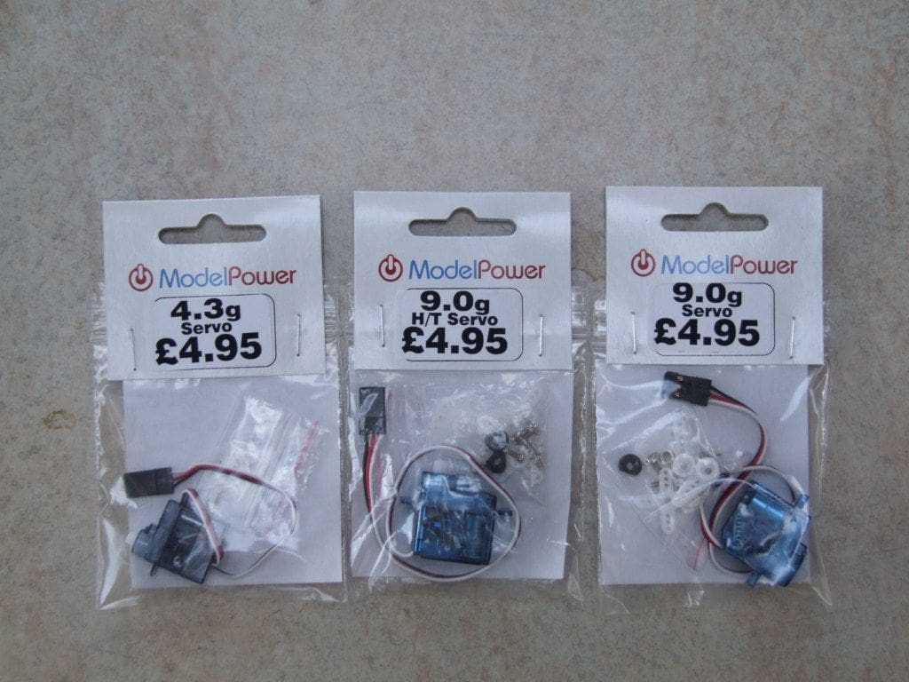
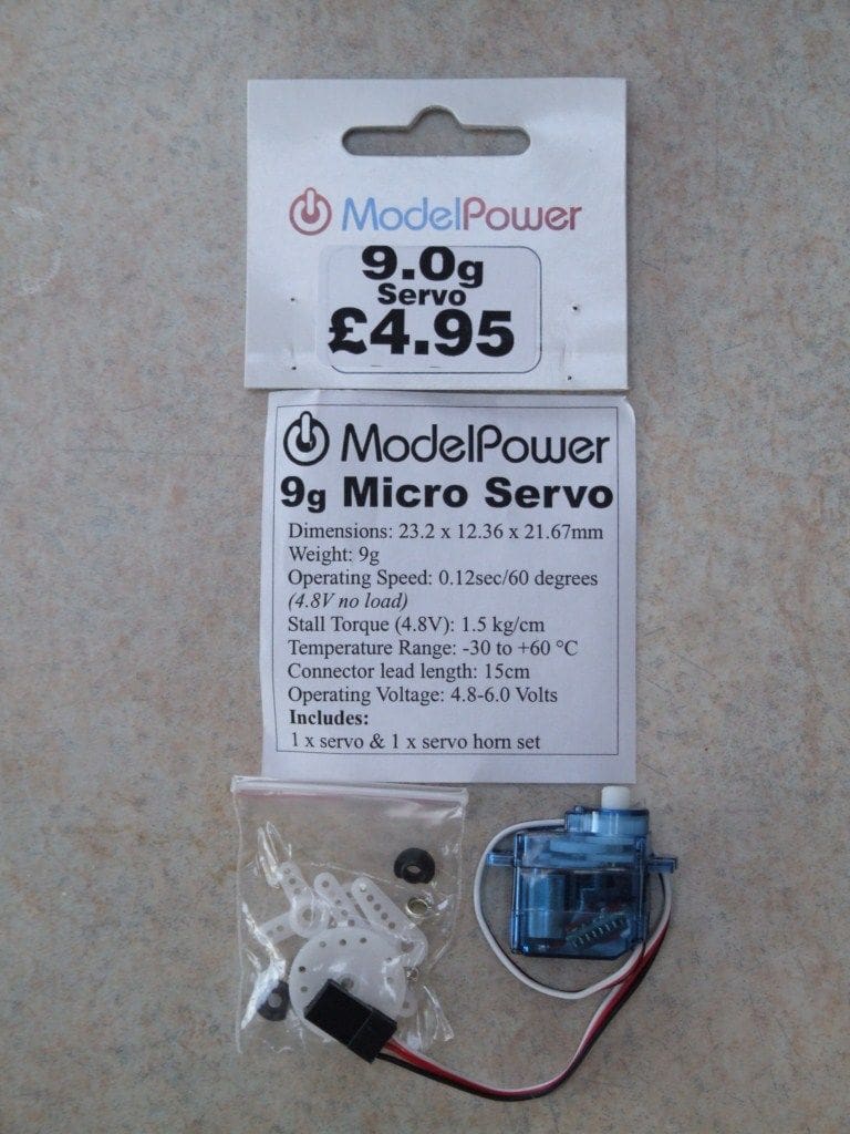
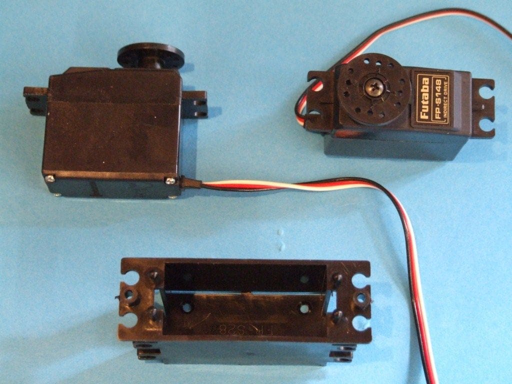
These are available in different sizes and degrees of power. Size wise, most radio sets are supplied with the manufacturer’s standard servos if they are included in the package. Mini and micro servos are also available as are larger servos for heavy duty functions. Photo 5 illustrates the normal different sizes available. The smaller ones would be used for very small boats (e.g. motorising plastic kits) or specialist functions on larger boats. Servo specifications usually include the physical dimensions, its weight, how fast it operates and the torque (twisting action) it is able to impart. Photos 6 and 7 are of part of the range marketed by ModelPower.
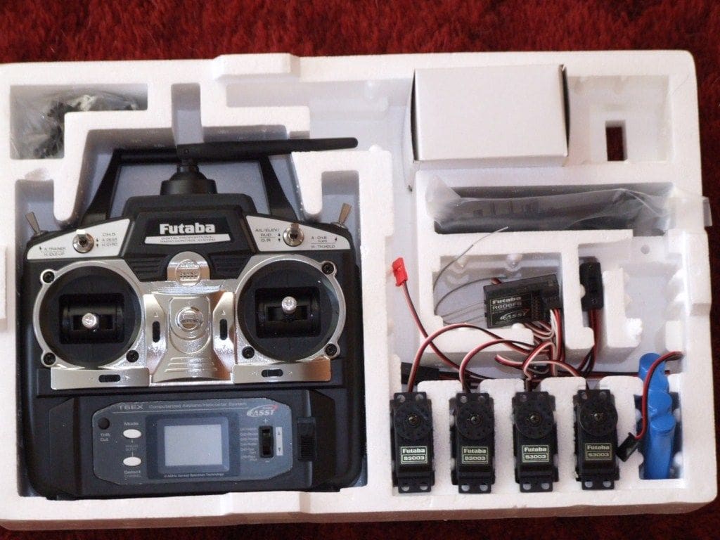
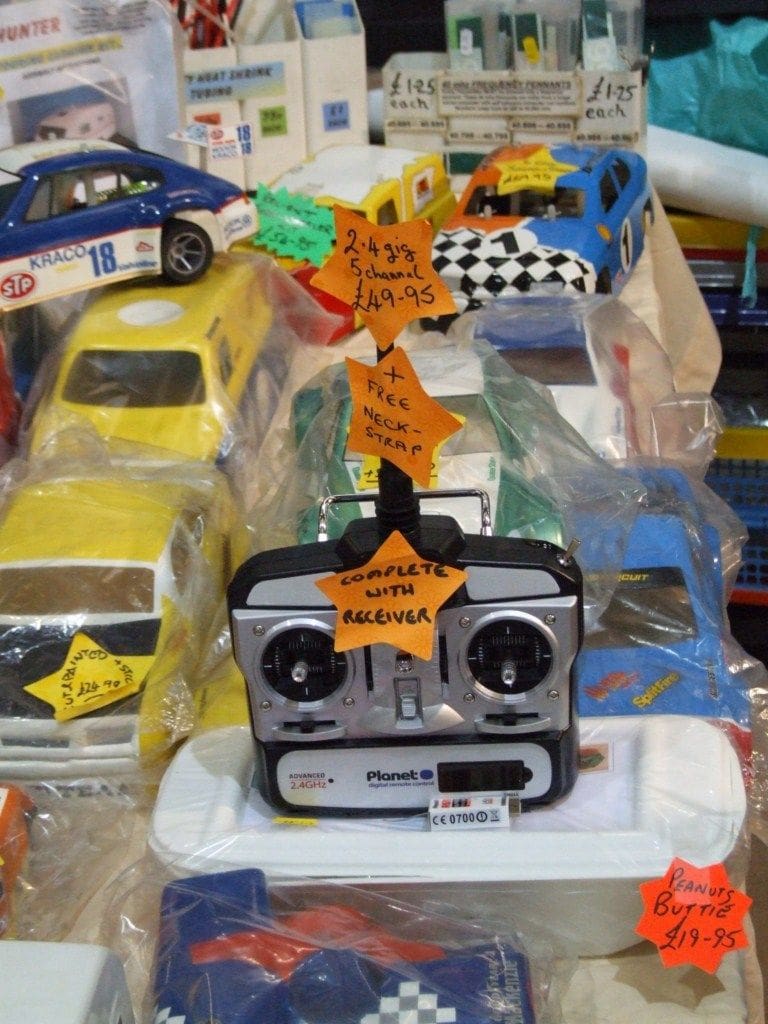
When first starting out in the hobby it is sometimes easier to buy (almost) everything in the box. This would include the transmitter, with battery, the receiver, four standard servos, a receiver battery pack and a charger for the transmitter and receiver batteries, Photo 8. Usually a selection of output arms and servo mounting screws are also included. With the growing popularity of the 2.4GHz radio market, prices have fallen with other manufacturers producing their own brands with for example a Planet outfit currently only £49.95, Photo 9. So we now have the radio and the servos, so what else is required? For those of us building and sailing electrically propelled models, some form of speed controller for the electric motor.
Speed controllers
A mechanical wiper resistance or an electronic controller is used for speed control. Many of the early types were mechanical in operation, requiring a servo to operate, but from the 1980’s onwards, electronic speed controllers started to appear and as time went on their reliability increased, so today it is rare to see anything other than esc’s (electronic speed controllers) in r/c electric models.
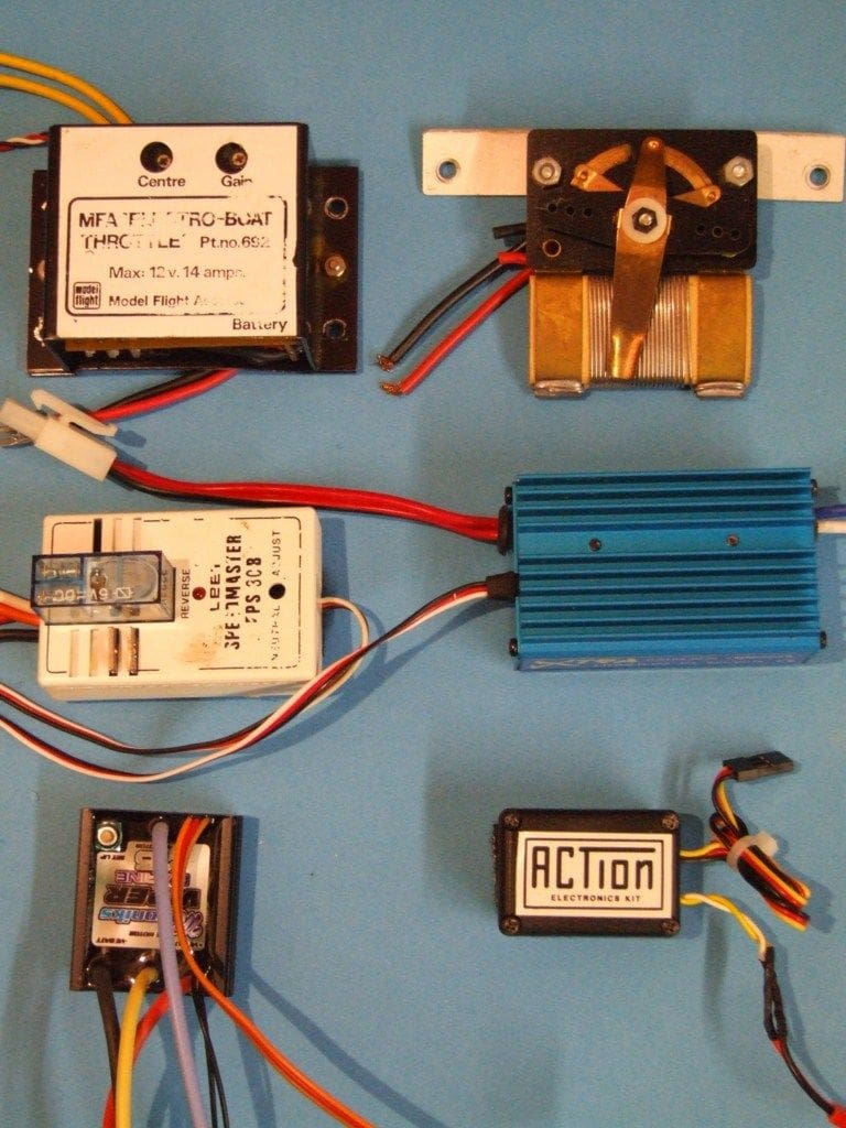
One of the early types was the MFA Electro-Boat Throttle which enabled full proportional forward and reverse control of the drive motor. Photo 10 illustrates these different types of controller with a wiper resistance type at the top right and one of the latest Mtroniks waterproof versions in the bottom left corner. As with servos, these have also evolved for different applications, with some capable of controlling motors that require a 24 volt supply and others more suitable for controlling motorised plastic kits. Some have a built in BEC (Battery Eliminator Circuit) which we will cover later. Most model trade shows and retail shops will have esc’s on sale from a variety of manufacturers, or please see the adverts in this magazine.
So far we have looked at radio control of two functions, namely steering and drive motor control. For model yachtsmen, a sail winch can be substituted for the motor control to give control over the model’s sails (its engine!). For this a basic two channel set is all that is required.
Sail winches
These come in two forms, lever arm or drum. Drum winches, Photo 11, are normally supplied with a two segment drum; the top segment usually controls the jib and the bottom segment the mainsail. A lever arm winch, is as its name suggests, is simply a normal but powerful servo, with an extended arm to adjust the sail sheet.
Auxiliary features
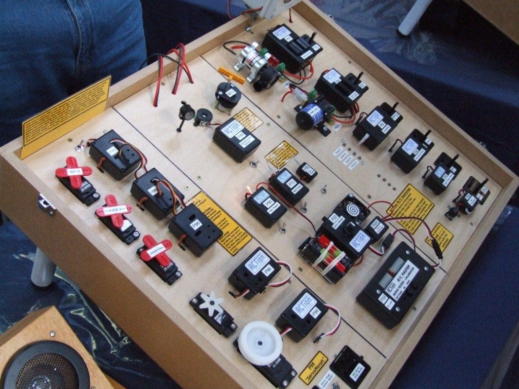
For the modeller who requires to control more functions, a multi-channel set may be required. Four or more channels are not unusual and the additional channels may be used to give independent control to two motors in a twin screw model, with the rudder still available on channel one, plus control of additional useful functions such as a working bow thruster, etc. Radio controlled switch units may also be used for turning on and off lights, an anchor winch, fire monitors, pumps etc. These switch units (switchers) are produced in different configurations, usually with either one or two functions which may be either on/off or off/on. Some have ‘latching’ relays which when activated stay on until getting a second signal to turn off. Others only stay on whilst being activated. Recently more sophisticated switchers have appeared in the market place that can control six or more different auxiliary functions from the same single receiver output. Photo 12 is of part of the extensive ACTion R/C Electronics range.
Power to the receiver!
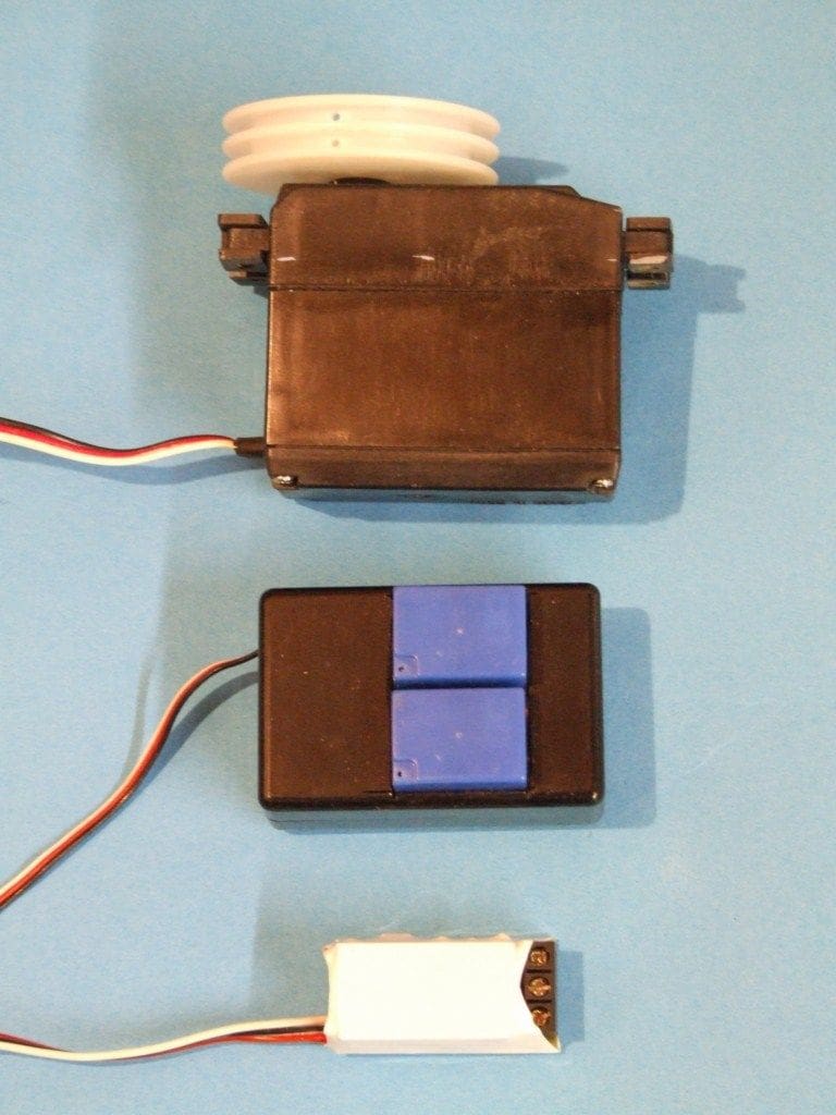
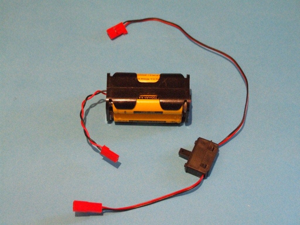
The radio control system in our model needs power to function. The conventional arrangement is by using a battery box (or holder), or a pack of pre-wired cells. This receiver battery box (supplied in some sets) usually holds four AA cells, Photo 13, which can be either dry (1.5v) or NiMH (1.2v). As NiMH cells are rechargeable, most modellers opt for these. This battery pack will power the receiver and its servos via a switch harness which may often include a charging socket for when the receiver battery is turned off.
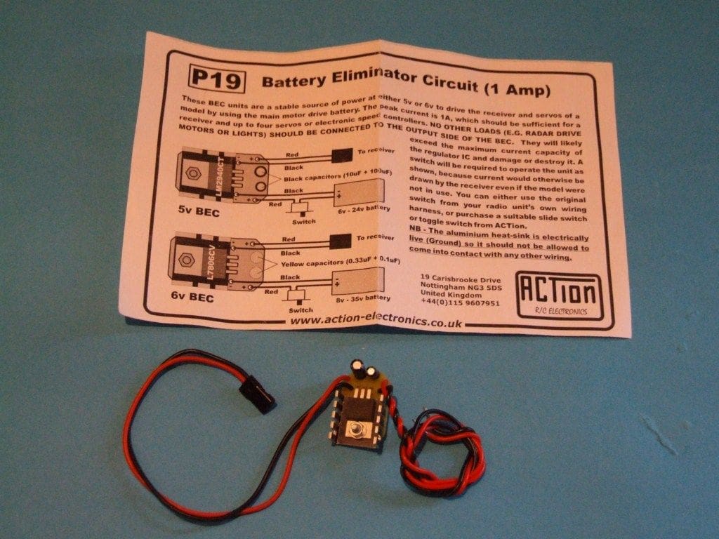
An alternative to a receiver battery pack is to use a BEC (Battery Eliminator Circuit) system. This is basically a voltage regulator which steps down the model’s drive battery voltage, typically 7.2v to 12v, to supply the receiver with a stable nominally approx. 5 volt input, Photo 14. These units are only suitable for powering a receiver and normally up to four servos and a speed controller and are not for providing operating power for the actual auxiliary function being controlled. Some electronic speed controllers have a built in BEC facility, the Mtroniks esc being such an example. The main power supply (which the esc controls for the drive motor) is regulated and then usually fed into the receiver via its connecting lead to the receiver. It is worth mentioning, that servos and esc’s all have a connecting lead with a plug that marries-up with a matching socket on the receiver. These leads have three separate cables, positive power, negative power and signal. In practice the power to a receiver system can usually be fed in via any of the receiver sockets and not just the one normally marked ‘Batt’. Hence the popularity of the BEC system as it is one less battery for the model to carry.
Installation
The next step to consider is the installation of the radio control equipment in the model. In all installations it is recommended that so called ‘dirty’ wiring, i.e. that which is carrying motor supply voltage, should be kept away from the ‘clean’ wiring, which is carrying output from the receiver to the various servos, switches and esc’s within the model. This helps to avoid interference, as does the positioning of the aerial lead away from the motor (which should always be suppressed).
Normally the first unit to be installed is the rudder servo. Consideration should be given to the installation of all components in the model. Will they be readily accessible once the model is complete so that adjustment and/or replacement is possible? Servos are normally supplied with fixing screws and grommets and a selection of output arms. Commercial servo mounts are available from different sources to make servo installation a bit easier, Photo 15. The operating arm of the servo is typically at 90 degrees to its pushrod, which in turn is at 90 degrees to the tiller. This configuration will ensure that the rudder can move an equal distance each side of the centreline. This is quite useful as they may be screwed down on to a mounting plate or secured to a bulkhead. In practice, servos may be mounted in a variety of ways including through a hole cut in a wooden mounting plate, Photo 16.
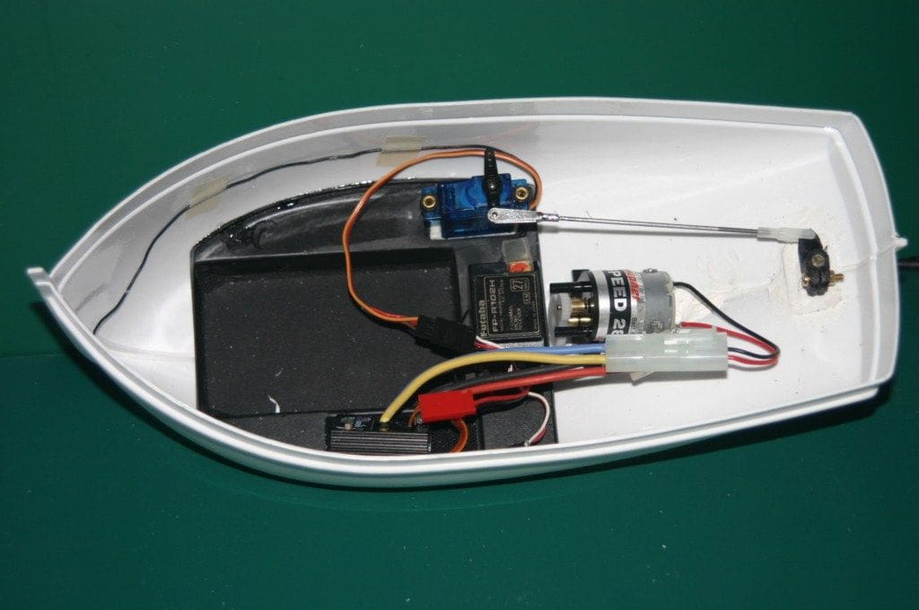
Some kits are supplied with a vac-formed mounting plate for the battery, radio receiver, esc and rudder servo, all of which simplifies installation, Photo 17. Where a low load is imposed on the servo, high strength double-sided mounting tape, often used in model aircraft, may be utilised instead, but generally speaking a physical fixture is more desirable.
Installation
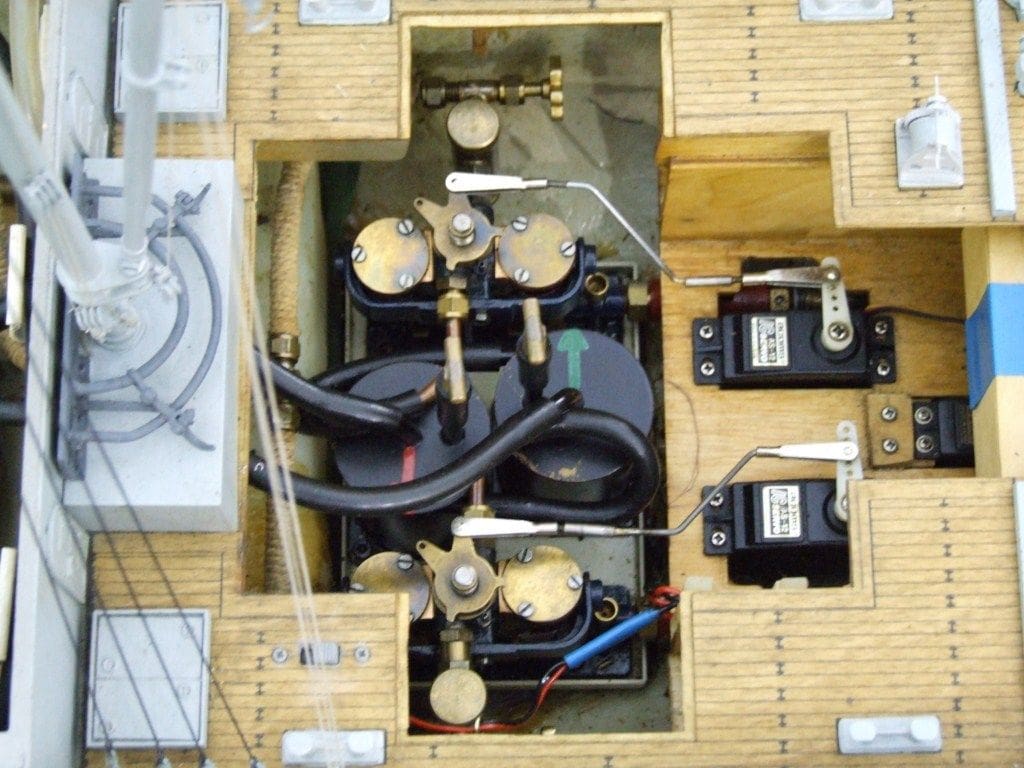
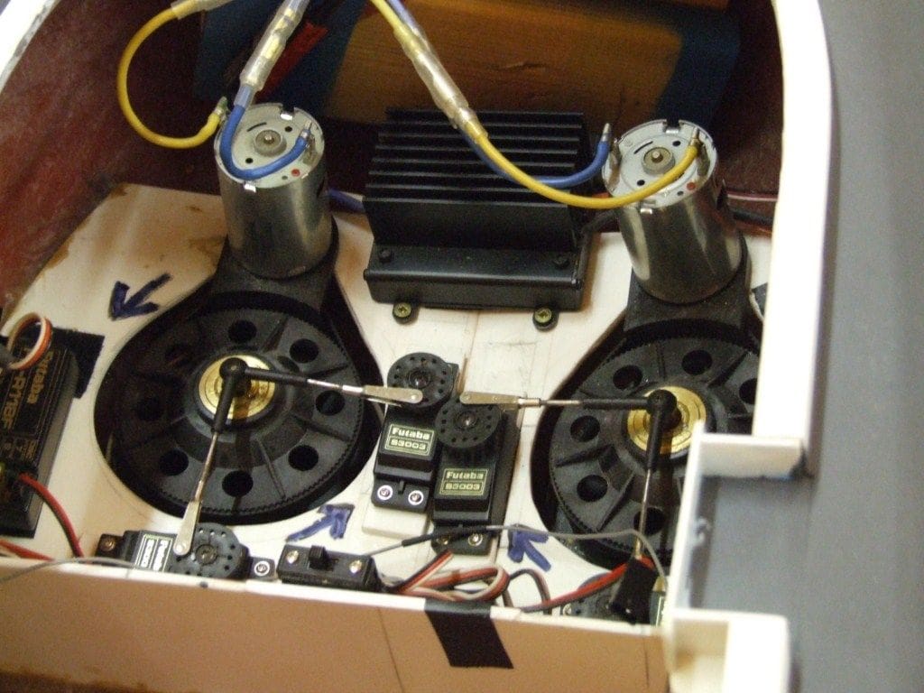
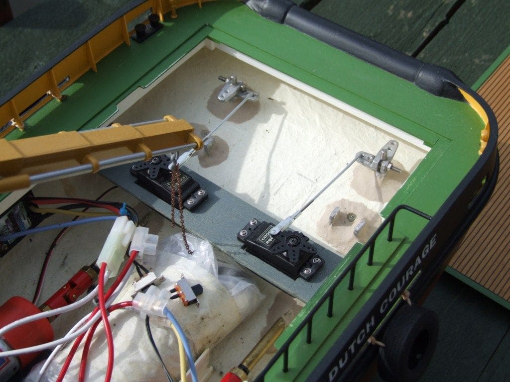
Four servos will be required for the operation of two Voith Schneider units and these should all be firmly mounted for the drive units to function properly. They may be mounted through a base plate, providing it has sufficient strength and rigidity and Photo 18 is of such an installation. A Voith Schneider unit is a vertically mounted blade system that can also steer the model by altering the angle of attack of the blades as they rotate, hence two servos are required to make these units work properly.
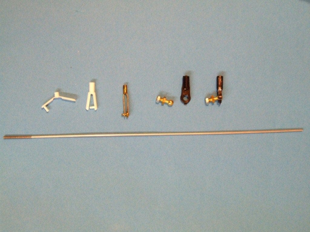
In normal installations, the linkage from the rudder servo to the rudder, or from the servo to the speed controller should be as direct as possible. It usually consists of a number of individual components as in Photo 19 which shows a number of choices for the end connectors. The ends can sometimes be threaded directly on to the rod, other times a joining fitting has to be soldered to the rod. I usually screw one of the parts on to the rod as far as possible, cut the rod to length and solder the metal connector to the other end. The metal end connector is usually fitted to the plastic output arm of the servo and the plastic part to the tiller arm as this avoids metal to metal contact which can generate electrical noise and may be a source of interference. Ball and socket joints are popular, providing a positive connection that is also easy to dismantle by just popping the socket connector off the ball.
In service adjustment of the pushrods can be achieved in a variety of ways. As well as using the threaded portion of the pushrod to lengthen or shorten the overall length, adjustment may often be made with the transmitter trims to get a model to sail straight. Using the metal connectors from ‘chocolate block’ wiring block, these ensure a pushrod can be almost infinitely adjustable for length as in Photo 20. As a further thought, 13 Amp plug pins can be adapted to make tiller arms, their wire clamping screw making a useful method of connection to the rudder shaft (please see Photo 20 again).
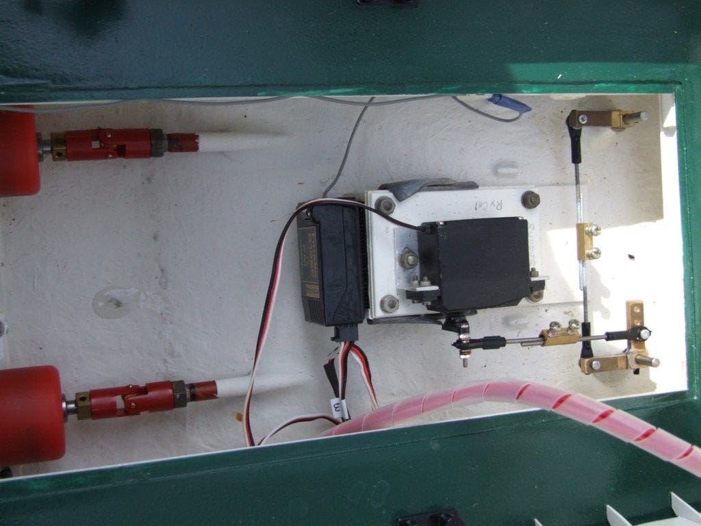
Here in Photo 21 we have both rudders operated by their own servo, rather than linked together. With separate control of each rudder independently, this could make a model very manoeuverable, although both servos operating in tandem with a ‘Y’ lead from the rudder channel of the receiver is more common. The servo pushrods in this last picture are connected to the white metal tiller arms with a ‘Z’ bend. This method is not too common these days as adjustment is difficult and there will probably be some slack in the servo to rudder linkage.
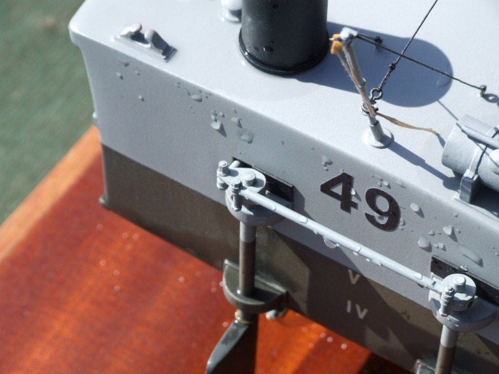
Different types of models may require different techniques. Sometimes the servo to rudder connection has to take place outside of the model as in Photo 22 of our Editor’s new Thornycroft MTB 49. When it is a scale model, this connection has to be discreet and in keeping with the full size version whenever possible. Although the pushrod may be seen emerging from the hull, if the connections are made with realistic nut and bolt connections it will not look out of place. On this model, there is only one pushrod through the transom that is sealed on the inside by a bellows, thus stopping the ingress of water through the opening.
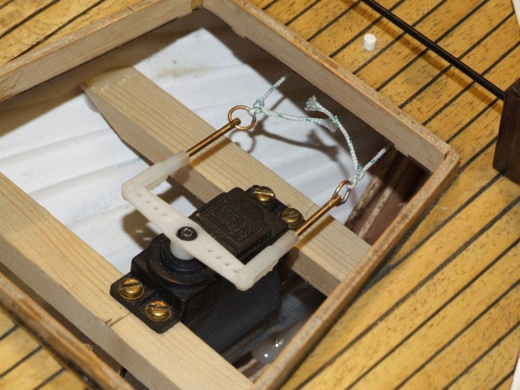
Sometimes a ‘push/pull’ connection to the tiller is necessary, Photo 23. This may be because the tiller describes an arc when the rudder is turned making a rigid connection impossible, so a push/pull technique is used.
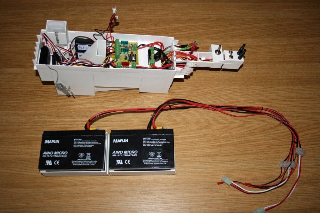
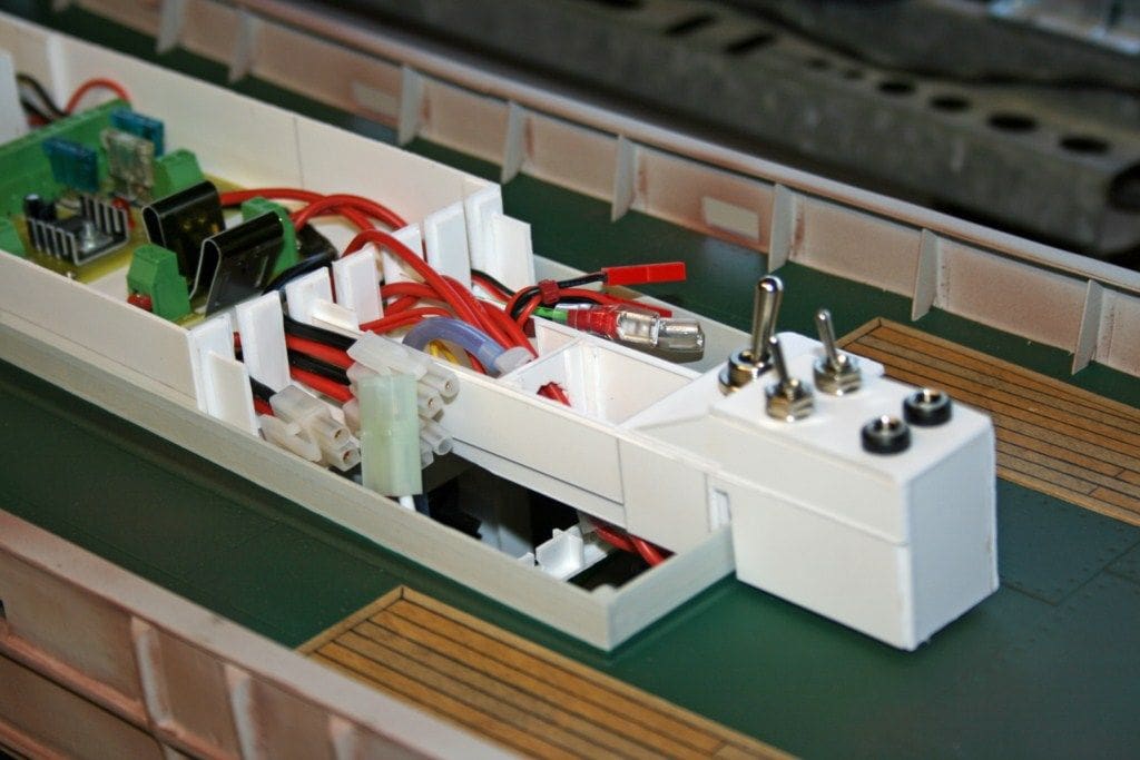
There are many other methods that the modeller may use for his radio control installation. One of our Brentwood MY&PBC members, Paul Godfrey, has demonstrated his technique which consists of installing all of the major components within a scratch built styrene box, Photo 24. This is one of the neatest ways in which to install the electronic components in the model as all of the switch gear, radio, smoke unit, auxiliary function controls etc. are installed within the box. When installed in the model, Photo 25, it is covered by the superstructure, which still allows access to the switches and charging sockets.
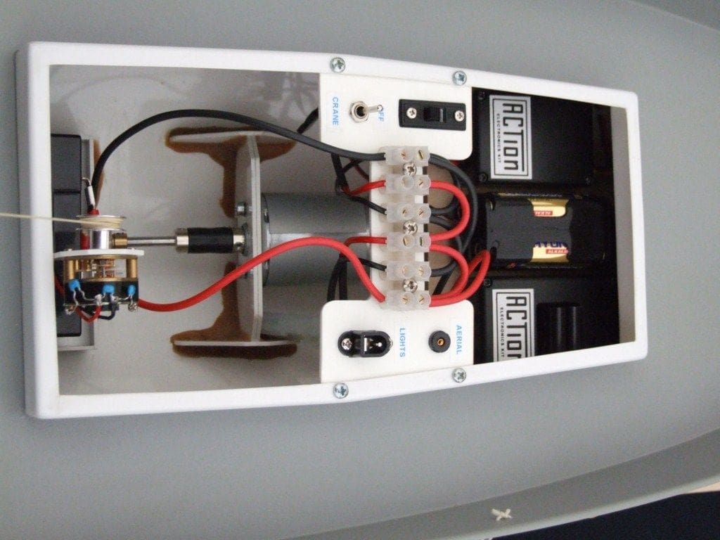
Even in the most basic model, a neat and simple installation with switches and sockets labelled, Photo 26, looks better than a haphazard mass of wiring and helps fault finding should it be necessary.
Conclusion
This has been a ‘whistle stop’ description of radio gear and its installation. There is no substitute for being in a club or making maximum use of the Model Boats Website Forum so that your questions can be answered and advice sought. Radio control equipment is evolving very quickly and is available at a fraction of the real price it was two or three decades ago, so we must be truly thankful for progress!
Good luck with your model boating! – Dave Brumstead

