Paddle Steamers Albion and Glen Rosa
While I was in the latter stages of the build of my last model I mentioned to one of the other members of The Model Steamer Club that I was thinking of building a paddle steamer as my next model. I said that I didn’t have any particular model in mind, so he suggested that I build a model of the Marchioness of Breadalbane, as the club didn’t have one. Phil Thomas who was also present and will be well known to many modellers, said that he had prepared plans for the model. To cut a long story very short, I started to make a model of the Marchioness, which was a lovely and very unusual old ship, using the David Metcalf hull for the P.S. Albion. However after getting to the stage when I had installed the paddles and drive motor, and cut out the openings for the portholes I decided that:
1. The builder’s plans that I had were too basic in detail to transform into accurate model plans.
2. The model itself was becoming quite a complicated project that would probably prove beyond the capabilities of the Model Boats readers for whom this article on the build of a paddle steamer was intended.
Enjoy more Model Boats Magazine reading.
Click here to subscribe & save.
As I said, the hull that I was using was the Metcalf Mouldings hull of the paddle steamer Albion. I therefore decided to complete the model using the Model Boats plans for that ship, which were drawn quite some time ago by Phil Thomas. You will have noticed that the heading for the article is PS Albion/Glen Rosa. Both ships are virtual sisters with only minor differences at both ends of the saloon, and a different colour scheme. This allows builders to choose whether they wish to complete the model as the Albion, or in my case the Glen Rosa, which spent most of her working life on the river Clyde.
P.S. Albion – the ship
The following is a précis of an article by Phil Thomas, published in Model Boats in May 1973.
The steamer traffic on the Bristol Channel developed during the nineteenth century in the form of a number of small companies, none of them reaching any significant size. In 1888 a new face appeared on the scene. The paddle steamer Waverley arrived from the Clyde, having been chartered for the season by Mr. G. H. Tucker of Cardiff. The Scottish owners, Robert and Alexander Campbell, noted her success with great interest. Things had not been going too well for them on the Clyde and so the Campbells decided to move south and open up a service in the Bristol Channel area.
Over the next few years they added to their fleet – four of the vessels were still operating during the Second World War – and by 1899 they had absorbed two competitors. In 1900 they commenced operations in the English Channel when they took over the Brighton, Worthing and South Coast Steamboat Company. Campbell’s had come a long way from the Waverley, now having 13 vessels in service. The Albion was built in 1893 by J and G Thomson of Clydebank, near Glasgow, as the Slieve Donard for the Belfast and County Down Railway Company. Two similar steamers were built at the same time; a true sister was the Glen Rosa for the Glasgow and South Western Railway Company, and a half sister, having one or two minor differences, the Minerva for the same Company. The Slieve Donard was purchased by Captain Alex Campbell in 1899 and was renamed Albion, the early name for England, for the 1900 season. She was requisitioned during WWI for minesweeping as HMS Albyn. Glen Rosa also acted as a minesweeper, chiefly in Belfast Lough and the Irish Sea, when she bore the title HMS Glencross. The registered dimensions of the sisters were 200.0ft x 25.0ft x 8.3ft with a gross tonnage of 363. On trials, Albion achieved a speed of 17.6kts. The model hull size at 1:48 scale, is 51 1/2ins in length overall with a beam of 6 1/2ins and a draught of 1 1/4ins. The model weight will be about 8lbs.
Colour scheme – P.S. Albion
Funnel White.
Hull Black to main rail, French grey above waterline.
Hull Bottom Pale biscuit with green boot topping.
Paddle Boxes White.
Pursers cabin Varnished mahogany.
Deck Scrubbed teak. The edge of the deck is carried round the side houses.
Lifeboats White, with white canvas covers.
Mast Varnished pine.
Flag Blue pennant with vertical white chevron and white ball.
P.S. Glen Rosa – the ship
The following is an extract from an article published in The Scottish Field, in December 1966 and text by George Stormier. If for no other reason, the Glen Rosa may be remembered as the last surviving member of the great Glasgow and South Western fleet. This company which was later than the Caledonian and the North British in acquiring vessels to maintain its Clyde coast service, began operations with second-hand ships in 1891. The following year three new vessels were built and in 1893 two more were ordered, of which the Glen Rosa was to be one. Shortly after construction began at Clydebank, the Belfast and County Down Railway took over one of the ships, naming her Slieve Donard. The two vessels were almost identical, but one had a more graceful sheer forward and aft. The Scottish Railway claimed this boat and she took the name Minerva. A third craft, identical to the Irish vessel, was then laid down and she became the Glen Rosa. Built to sturdy specifications, Glen Rosa and her near twin were intended for off-season work on the Firth and to help out where required during the summer months. The promenade deck was not carried far beyond the mast, but the cutaway bow was covered over at bulwark level and railed off.
The front end of the forward saloon was extensively strengthened and altogether a more formidable pair of winter boats could not be found anywhere. In the engine room the powerful little pair of diagonals were smaller editions of the heavy machinery, characteristic of the Princes Pier boats and produced a good turn of speed. Towards the close of her career Glen Rosa had lost pace to a marked degree and those who were unfamiliar with her early success as a pacemaker, were apt to hold her to ridicule. During World War One, she acted as a minesweeper, chiefly in the Belfast Lough and the Irish Sea, when she bore the title HMS Glencross. On her return to the Clyde, her summer season running was almost entirely devoted to the Millport and Kilchattan Bay route, at first from Fairlie and later from Wemyss Bay when she came under LMS control. Glen Rosa continued to serve the Cumbrae until the final year of her existence when as in her initial season, she was engaged in an assortment of cruises from the Clyde resorts. Just before the declaration of war in 1939 she was taken to Arnott Youngs at Dalmuir and broken up.
Colour scheme, P.S. Glen Rosa
Funnel Scarlet with black topping.
Hull Light grey to about 6ins under deck line, white above.
Below the waterline Dark red
Additional details of the colour scheme will be given later in this series of articles.
Paddle boxes White with the South Western Company’s house crest painted on a circular panel on the sponson.
Purser’s cabin Varnished mahogany.
Deck Scrubbed teak.
Lifeboats White with white canvas covers.
Mast Varnished pine.
Flag The gold coloured badge of the company, on a pennant, with a blue background.
Albion/Glen Rosa – the model
I started composing articles for Model Boats magazine a number of years ago, in the hope that they would be of interest to readers who may not have previously scratch built a model, and would perhaps be encouraged by them to do so. I do however despair that scratch building seems to be a thing of the past as all I ever seem to see in magazines these days are models built from some fairly expensive kits.
As usual I have tried to keep construction of the model as simple as possible, using easily obtainable parts and only basic tools. Like most modellers I don’t have a lathe or access to one. In common with most of my models, all the external surfaces other than the deck, are constructed from plasticard. They are therefore impervious to water damage and will not deteriorate when exposed to the elements, as can be the case with wood however well protected. Similarly, all parts that may require replacing due to damage or other failure are easily accessible without having to cause damage to the model. The measurements used throughout the articles are generally imperial. This may cause a little inconvenience to some builders, but I am too old to change to metric measurements and my attempts to give both sets of measurements would only lead to confusion. I use two steel rules in my modelling and both have conversion tables, from imperial to metric on their reverse side, so conversion to metric should not be too much of a problem.
The last time I built a paddle vessel featured in Model Boats was in January 2000, when I built Talisman. While many readers will have read this series of articles, most new readers will not have done so. Numerous points, which I mentioned in the Talisman articles, such as methods of painting etc. were repeated in this model. Although Albion/Glen Rosa is not a model for the novice builder, she should be well within the capabilities of most builders with the experience gained from building a couple of reasonably complex models. I have carefully detailed all stages of the construction and described the making of templates for major parts.
The model itself is fairly simple, the fore and aft saloon sides being flush with the sides of the hull. She has a single funnel and one mast. The only superstructure on the main passenger deck is a small ticket office, above which is the open bridge. The windows in the saloon will require some care, as they will all have to be identical.
The plans
As I stated earlier, the plans for the model were drawn by Phil Thomas from the builder’s plans and are available from the Model Boats Plans Service. (Plan number is MM1165 available from www.myhobbystore.com.) Usually my first port of call is the local photocopying facility to copy the plans onto A3 size paper, and I would recommend that you consider this course of action. I make two copies. One set is taped together to use as working plans, the other set being used as templates as required. I normally do this because I am hard on plans, drawing on them, cutting on top of them, etc. However in this case I was fortunate to have two copies of the plan and was able to use one as a working copy. As usual I spent some time just looking at the plans. This can save a great amount of time later in the build and despite doing this I have made mistakes. However if I make them, then hopefully modellers following the articles will not!
Parts required
The great thing about scratchbuilding is that you don’t pay out all the cost of the model at one time. Parts can be purchased as the model progresses, which is a great advantage for modellers who are on a budget. Whilst scratchbuilding a model such as this is not cheap, it is certainly much cheaper than purchasing a kit, especially if that kit has literally hundreds of parts, most of which are quite unnecessary for a model whose primary purpose is to be sailed, not exhibited. Several hundred small parts are quite invisible when a model is 20 feet or so out from the side of the pond.
Before starting the build, I make a list of the parts required to complete the model. I decide on the parts that can be purchased, and the ones that I will have to make, and try to order them so that they are delivered as required. Most of the difficult parts on this model, such as the portholes, running lights, stanchions and lifeboats can be obtained from the list of suppliers listed at the end of Part One. They are not inexpensive but they are quality parts.
Access to parts within the model
I always try to gain the maximum amount of access into the interior of a model, bearing in mind that batteries have to be positioned and removed. Faulty motors, servos and speed controllers may also have to be replaced at some time. I never put anything such as a steering servo into a model in a position that it can’t be accessed without having to butcher the deck or superstructure. A little foresight can save a lot of hassle later.
Adhesives
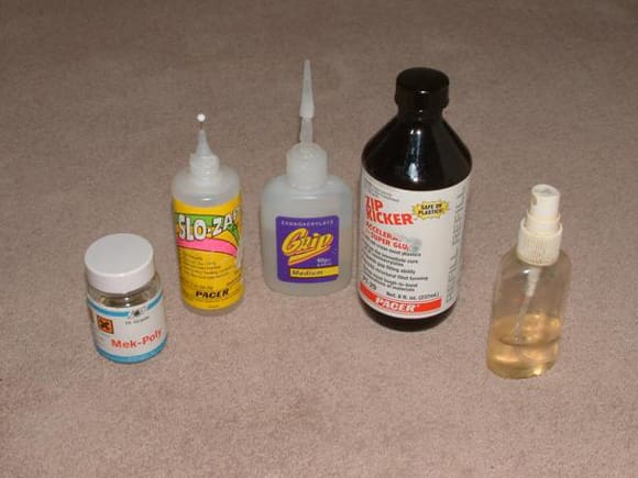
Before progressing with the build I would like to mention the types of glues, which I used in the construction of the model, Photo 1.
Epoxy adhesive. Commonly known as Araldite or by another brand name. I used Bond It Epoxy Adhesive, because it only cost £1.99 at a local market. Why pay more? You’re not going to swing on the joint. Cyano or Superglue. I use two makes – Pacer and Grip. I use Pacer Slo-Zap for jobs where I don’t want instant grip. This product is a very slow cure cyano, which lets you move the parts about for some time before it sets. It’s the only product I know which allows you to do this. I also use Pacer Kicker, which is an accelerant that when sprayed lightly onto any make of cyano glue, bonds it instantly. The chemical reaction produces a tremendous amount of heat so it must be used sparingly and not at all on very thin plasticard as it will melt and destroy it! It will also inflict a very painful chemical burn on the skin if any cyano is on it and is near the spray when applied. (True – and if you then plunge the affected area into water to cool things, it only makes it worse. Personal experience – Editor!) Another cyano that I use is Grip, which comes in three types, thin, medium and thick grades, because for an equal quantity it’s cheaper than Pacer. Mek Poly is a solvent used to join plasticard to plasticard. It welds the surfaces together and is applied with a small brush. If used carefully it can also unweld surfaces if you have made a mistake. It is both highly flammable and harmful if inhaled and should only be used in a well-ventilated area, with no means of ignition present. The warning about well-ventilated spaces applies equally to the use of the cyano glues.
First stage of the build
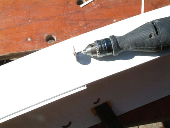
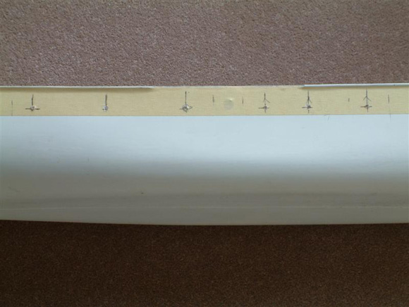
The build started with the initial preparation of the Metcalf Mouldings hull. This was a very good quality white coloured fibreglass hull, although there were a few breaks in the moulding around the top which were easily filled. I washed the hull surface in warm water with a touch of washing-up liquid and gave the surface a rub down with 600 grade wet-and-dry abrasive paper, to gently break the surface of the gel coat to create a key for the paint. The hull, as supplied, has about 3/16ins of surplus fibreglass above the top edge of the hull bulwark, which is defined by a ridge running around the hull, Photo 2. This surplus was cut off using a Minicraft power tool and cutting discs. I say discs, because I used quite a number. They frequently shattered due to flexing of the surplus material, making it an expensive operation. I decided that the next stage would be to drill all the openings in the hull, for the paddle shaft bearings and the portholes. The most important holes to be drilled were for the paddle shaft bearings. While the portholes could be a few millimetres out of position lengthwise without causing a problem, the paddle shaft bearings had to be absolutely accurate.
Paddle shaft bearings
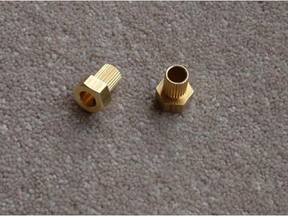
The bearings in the hull for the paddle-shaft consist of the brass inserts, which are used at each end of the Dyco universal couplings that are fitted between the drive motor and propeller shaft in propeller driven models, Photo 3.
Paddle shaft position
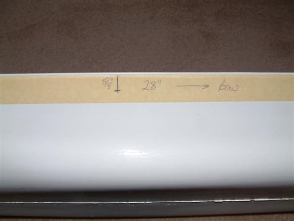
During the build of Talisman I had spent a considerable amount of time trying out various paddle shaft positions and paddle sponson heights above the water. If the bottom of the paddle sponsons are too close to the surface of the water and the paddles cavitate (travel too fast for the speed of the model and cause froth and bubbles), then the bottom of the sponson sticks to the water, slowing down the model. I found that the most suitable position for the paddle shaft on Talisman was 3ins above the bottom of the hull. This gave about an inch of freeboard between the bottom of the sponsons and the water. This gave me a good starting point in positioning the paddle shafts on the Albion/Glen Rosa. After taking a fair amount of time to decide, I settled on a position 2 3/4ins above the bottom of the hull, and 27 1/4ins back from the bow. The bottom edge of the paddle sponsons would be 2 1/2ins above the bottom of the hull, Photo 4.
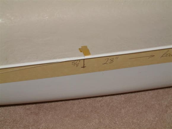
To scale, the water level on the drawing of the prototype at a 6ft draught was 5/8ins below the sponson. Maintaining that distance on the model, with the 5/8ins increased depth of the hull, would give me a draught of up to 1 7/8ins, with a fair amount of the waterline still showing. This should be more than adequate for what will be in the hull and I imagine that a fair bit of ballast will be required. Remember that you can always add weight into a hull after all the components such as batteries, speed controllers and radio gear are installed. If you have no reserve of buoyancy after these items are installed, you’re in trouble!
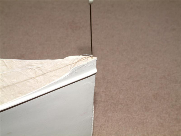
Using much the same method as when building Talisman, I measured this distance back from the bow using a flexible tape measure. After the position was marked I projected it up to the top of the hull. I then drilled a small diameter hole at the bow, into which was inserted a pin, Photo 5. I attached a length of thread to this pin and led it back to the paddle shaft position on the left side of the hull. I attached a piece of masking tape to the thread where it passed over the projected paddle shaft position, Photo 6. I then moved the thread across to the other side of the hull and found that the piece of masking tape passed over the paddle shaft position on that side of the hull, confirming the accuracy of my measurements. This check ensured that the paddle shaft was at right angles to the centreline of the hull, and that the paddles when fitted would be running absolutely parallel to the sides of the hull.
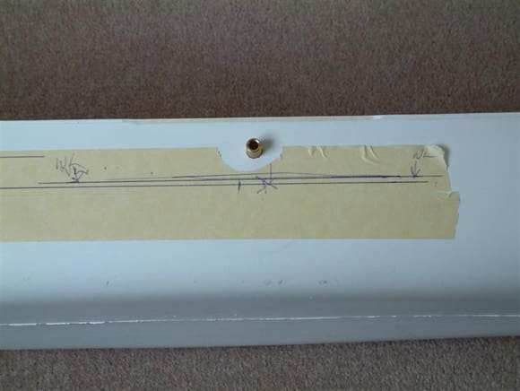
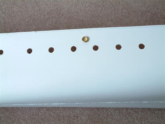
A pilot hole was then drilled at this location on each side of the hull and then enlarged to 8mm diameter to take the brass bearing. When enlarging the hole, take care to ensure that its centre remains at the correct location. Photo 7 shows the shaft bearing in position on the hull. The bearing is inserted in the hole from the inside of the hull with the splined part facing outwards. Make sure that the hole for the grub screw is at the top, as with the grub screw removed it is an excellent oil pot! The bearing at this stage is only held in place by a tack of cyano! Do not glue it firmly in position until the hull frame is in position and the paddle shaft is inserted, or the alignment of the bearings and the shaft will most definitely be out of true. The picture also shows that the rim, which runs around the top of the hull, has been sanded down flush with the side of the hull at the position of the paddle box.
Porthole openings
Note that the positions of the portholes in the pictures of my hull don’t correspond with those on the Albion/Glen Rosa plans because they are positioned according to the plan for the Marchioness of Breadalbane. I did consider filling them in and starting again, but as they will not be obviously wrong to anyone but me, I decided to take the easy course and leave them as they were. Consulting the plans you will see that there are five portholes under the aft end of the paddle sponson. I would recommend that they be omitted from the model as they will not be visible and, as they are only 1/4in above the waterline they could be the source of leakage of water into the hull in the disturbed water behind the paddles. This leaves five portholes aft of the sponson and ten forward of it. There are also a number of brackets under the sponson, which are quite unnecessary on the model and they should also be omitted.
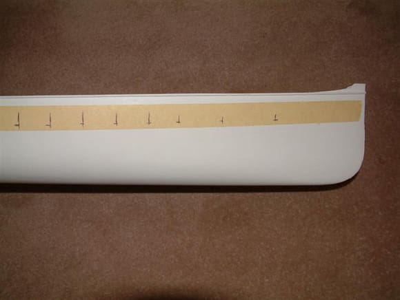
When drilling the portholes, their positions should be marked on to the hull on top of strips of masking tape. This makes it easier to mark the position of the holes and also helps to ensure that the small bit used to drill the pilot hole doesn’t wander from the correct position, Photo 8. After the pilot holes were drilled, the masking tape was removed, and the holes enlarged using a 1/4in diameter drill, before being filed out to their final size of 8mm. Photo 9 shows one of the portholes which was used to check the size of the holes in the hull. If you try to take a shortcut and drill the holes out to their final diameter using an 8mm drill, then you will find that the fibreglass hull around the hole will be damaged. You will also probably find that one or more of the holes will be out of line.
Graupner paddle units
The Graupner paddle units that I used are the only reasonably priced ones available on the market. In saying that, they still cost around £50.00, which is a lot of money for a few pieces of plastic, brass rod and pins. You would think that at that price Graupner would include a reasonably detailed instruction sheet. Wrong – they include a schematic drawing and leave you to figure out the rest. The main omission and a very important one, is that they don’t give the position of the pin that controls the paddle feathering gear. Get the position of this pin wrong and the feathering paddles won’t work correctly. When building Talisman I had to phone around numerous model shops until I found one that had a Graupner Glasgow kit and it was kind enough to give me the position from the instructions in the kit. According to the Graupner instructions the position of the pin is 1/4in forward of the paddle shaft and 1/4in above it. They are made apparently to the scale 1:40, so when used on a model at 1:48 scale, larger than scale paddle boxes are usually required. This was indeed the case with Albion/Glen Rosa. After making several enlarged photocopies of the paddle boxes in the plans, I decided to make the sides of the boxes 125% larger than those in the plans. However I found that the width of the paddle boxes in the plans was such that the Graupner paddles would fit into them without any increase in the width of the boxes or the sponsons.
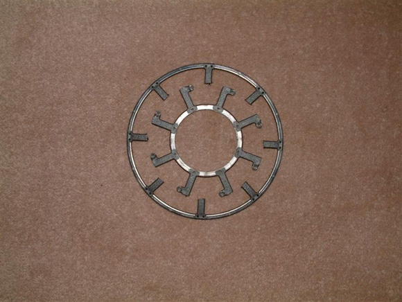
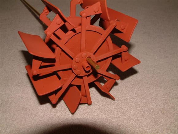
This increase in size meant that later in the build some compromise would have to be made to the details of the sponson housings and other details in front of and behind the paddle boxes. The first stage was to cut off the outer rings of the frames just above attachment points for the paddle blades, Photo 10. The paddles were then put together following the illustration leaflet supplied with the kit.
Before starting, you must remember that the paddles are handed, and that you are making one port and starboard unit. Be careful not to make two identical units. Following the instruction illustrations, part two the gear rims with the outer ring removed, were fixed on to part one which is described as the nut. Small spots of cyano were then applied to the locating pins and along the inside edge of the gear rims to secure them in place. The paddle blades were then fixed onto the gear rims using the small plastic rivet type parts called king pins. There is nothing in the instructions to give any indication as to how these pins will be kept in place. They are a good tight push fit and shouldn’t work free. However, as in the assembling of the Talisman paddles, I put spots of thick cyano on the inside edges of them where they fitted through the black coloured gear rims, and immediately applied a thin spray of kicker to each pin. Don’t use thin cyano for this job as it will probably seep past the pin and glue the paddle blade solidly onto the gear rim. However don’t apply any cyano to these pins until the assemblies are completed and you have checked them for accuracy.
Feathering assembly
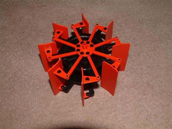
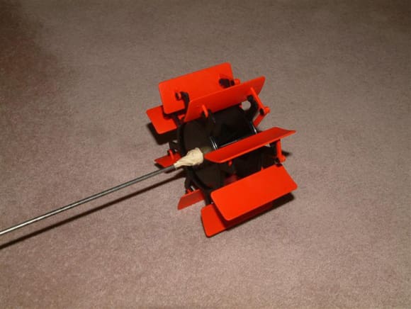
Before assembling this part, go forward to the paragraph headed ‘Paddle shaft construction’. After I had finished fitting the paddle blades I built the feathering assembly, part five in the schematic drawing. The pushing rods, part four in the drawing, were fitted to the control disc and the other ends to the paddle blades. As before, the plastic rivets were secured with spots of thick cyano, Photo 11. The completed paddle assemblies were then attached to lengths of scrap rod, Photo 12 and sprayed with several thin coats of red oxide acrylic primer purchased from the local auto shop, Photo 13. I know that the paddle blades would have been made of wood and you can paint the individual blades if you wish, but I didn’t bother as they wouldn’t be seen.
As I stated at the beginning of the article in the paragraph entitled ‘Access to parts within the model’, I make sure that I have easy access to any parts which may have to be replaced or repaired after damage. This also applies to the paddle assemblies, which are all too susceptible to damage from objects in the water. There will come a time sooner or later when one of the paddle assemblies will have to be either repaired in situ, or removed from the model. Turning a large model upside down, with a lot of easily damaged fittings such as lifeboats and deck rails, is a bit of a nightmare. With this in mind, when I built the Talisman I made the paddle sponsons to which the paddle boxes were attached, removable. While this method of construction had the advantage of giving easy access to the paddle assemblies, it also had its problems. I therefore decided to fix the paddle sponsons on the Albion/Glen Rosa to the hull, and make the paddle boxes easily removable. This will be relatively simple, as you will see as the build progresses. Additionally, the drive between the motor and the paddle shaft is transmitted through a rubber drive belt, which could obviously have to be replaced from time to time. My initial thoughts were that the only way that this could be achieved, without cutting and re-joining the belt, was to have a paddle shaft that could be easily taken apart, and reassembled.
My initial idea was to make the paddle shaft in three pieces, using brass rod and tube of various diameters. The idea being that the rod and tube would telescope into each other within the hull, allowing the paddles to drop down out of the sponsons, and also allow the drive belt to be replaced. However it began to get a bit too complicated and I had to rethink the whole idea. The problem was how to remove the paddle shaft from the paddle assemblies, and the hull. After thinking about the problem for about a week while I proceeded with other parts of the model, I decided to see if a one-piece shaft could be removed through the paddle assemblies. I found that it could, but unfortunately I had by this time already built the paddle assemblies.
I found that if I drilled a suitable sized hole in the control disc of the feathering gear, I could push the paddle shaft out through it. This greatly simplified the construction of the paddle shaft as it could be built as one piece. There was only one place on the control disc where this hole could be situated and that was where the one rigid pushing rod was attached to the disc.
As I hadn’t tried this before, I approached the operation with some trepidation, considering the cost of the Graupner paddle assemblies. Additionally I didn’t know if I could obtain a replacement part if the operation went badly wrong. I started with a 1/16ins dia. pilot hole in line with the centre-line of the pushing rod and also in line with the holes for the plastic rivets. The operation was complicated by the fact that the paddle assemblies were finished. It would of course be much simpler if the hole were drilled before the control disc was attached to the paddles. Using progressively larger drill bits, the hole was enlarged until it was about 5.5mm diameter, just large enough to allow the 5mm diameter paddle shaft to pass through freely. I found no problem with this operation, even with the paddles assembled. However I must emphasise that the operation must be done with some care, allowing the drill bit to work, without forcing it, Photo 13 again.
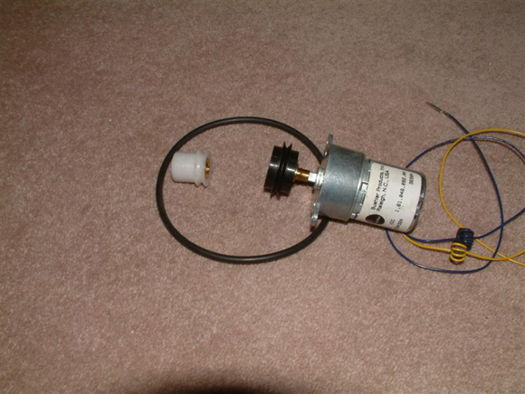
Drive system
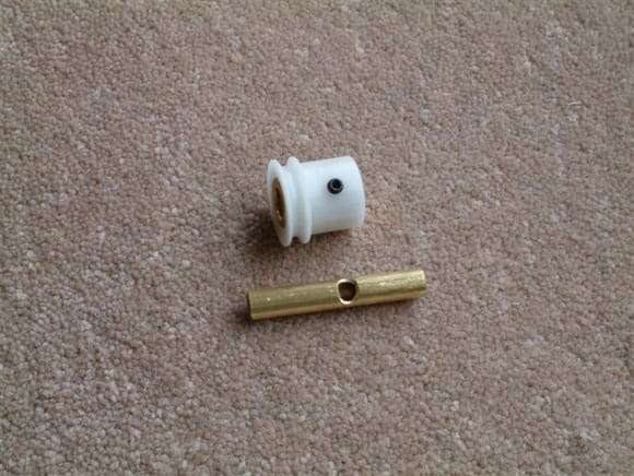
My first choice of drive motor for this model was the Model Motors Direct PPB1 (M), 12v motor, which is supplied with two pulleys and rubber drive belt to reduce the final drive speed to 60-110rpm, Photo 14. In later test sailings of the model I found that the smooth drive belt had a tendency to slip, so I would recommend the optional chain drive. The larger, black coloured pulley is attached to the drive motor and is a tight push fit on the shaft, which is about 5mm diameter and has a flat machined onto it. It is recommended that this pulley be epoxied to the shaft. The smaller white coloured pulley has an internal diameter of 6.5mm and requires to be bushed down to fit the paddle shaft. Photo 15 shows the drive pulley and the bush, which was required to reduce its inside diameter from 6.5mm to the 5mm diameter of the drive shaft. So a 1 1/2in length of 5.5mm brass tube was cut and fitted on to a long piece of 5mm tube, which was held in a vice to make the assembly easier to work on. A hole was filed through both tubes, using a round file, to allow the grub screw on the drive pulley to pass through both tubes and engage in the flat filed on the paddle shaft. Once this was completed, the 5mm tube was also cut to a length of 1 1/2ins.
Alternative Drive System
For modellers who may find difficulty in obtaining the above PPB1 motor and pulleys I can recommend an alternative. Looking through my spares box I found a 3:1 reduction gearbox marketed by Model Flight Accessories (MFA). I mated a MFA/Como Drills 6v to 15v motor, Part No. 457-RE385, to the gearbox and transmitted the drive to the paddle shaft using a toothed belt and pulley system. The toothed belt and pulleys, which were both the same diameters, were obtained from Model Motors Direct, but any suitable pulleys can be used. For comments on sailing the model with both drive systems, I an afraid you will have to wait until a little later in the series.
Paddle Shaft construction
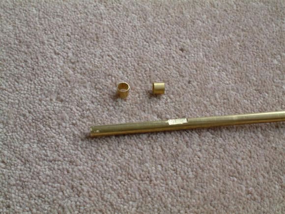
I made mine from 5mm diameter brass rod, a size readily available at most model shops. The rod was cut to a length of 11ins and two 5/16ins flats were filed, with their outside edges 1 3/8ins from each end of the shaft. These flats were for the grub screws on the brass bushes on the inside of the paddle assemblies. Another flat, 1/2ins wide for the grub screw on the drive pulley, was filed with its outside edge 4ins from one end of the shaft. This flat is not in the centre of the shaft because the drive pulley is offset to the starboard side of the shaft to keep the centreline of the motor in the centre of the hull. Two 3/16ins long pieces of 5mm inside diameter tube were also cut, to be used as spacers between the brass bushes on the inside of the paddle assemblies and the outside ends of the paddle shaft bushes. These spacers would be the small but vital parts which would hold the paddle shaft in its correct location in the paddle box, Photo 16.
Motor mount and hull baseboard
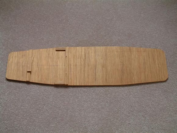
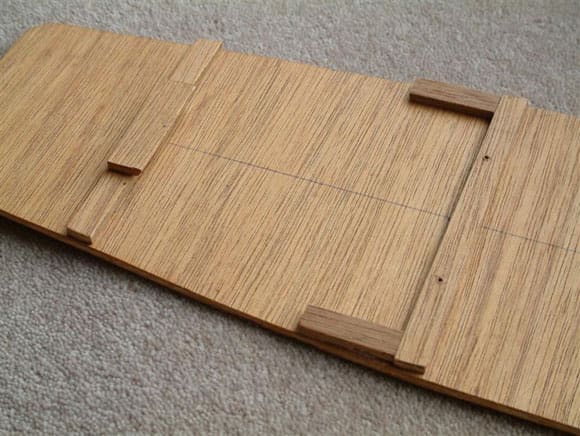
The next parts to be constructed were the motor mount and a baseboard for the bottom of the hull. Both parts were made from ordinary 4mm plywood, admittedly not of top quality. I used this because it was snowing heavily at the time and very cold, so I didn’t relish a trip to the model shop for better quality wood. It was in any case perfectly adequate for the purpose. The base, which will hold the motor mount, drive battery, speed controller and other accessories was cut to fit the shape of the bottom of the hull, Photo 17.
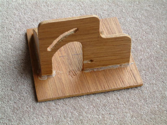
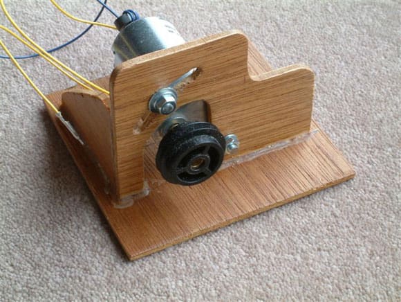
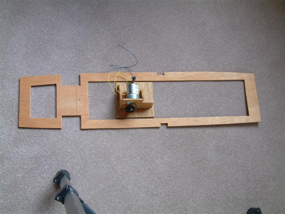
Photo 18 shows the motor mount, the base of which measures 4ins square. It consists of four parts glued together with cyano. One of the motor mounting bolts is fitted into a hole at the bottom of the mount, while the other is fitted into a slot cut into the mount to allow a range of adjustment for drive belt tension. Photo 19 shows the mount with the motor fitted.
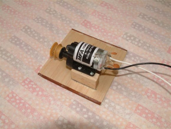
Photo 19a shows the alternative drive motor that I mentioned earlier, again mounted on a 4ins x 4ins base which makes it interchangeable with the PPB1 motor. As you can see, at this stage the motor mount was made from scrap balsa etc., mainly to ascertain if the drive system would work satisfactorily.
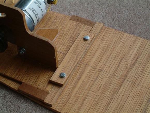
Not wishing to have the motor mount glued firmly onto the hull baseboard, a simple mounting bracket was made from 3/8in wide strips of scrap ply and glued in position, Photo 20. The position of the motor mount depends upon the length of the drive belt supplied. The drive belt should be taut, otherwise it will slip and fail to transmit the drive. It must not however be strained, or it will cause the motor to demand a high current, reducing the running time and the life of the motor.
A piece of 1/2ins wide ply about 1 1/2ins long was glued to the rear of the mounting bracket to hold the back end of the motor mount in position. Another piece, 5/8ins wide x 3ins long was cut to fix the front end of the motor mount to the bracket, allowing the motor mount to be easily removed and replaced, Photo 21. On completion, the baseboard and motor mount were sealed from moisture with a couple of coats of varnish.
Hull width (beam)
The width of the hull supplied by Dave Metcalf should have been 6 1/2ins, but it was in fact around 7ins at its widest point. It isn’t unusual for this to occur in a fibreglass hull after it is removed from the mould.
In his construction booklet, Dave recommends that if the hull is too wide then string tourniquets should be placed around it, twisted until the hull is narrower than needed and then it should be left in the sun for a couple of days. This with the aid of the heat from the sun should pull the hull in. I was working in Scotland in the middle of winter, when we try to remember what the sun looks like, so this was not too practicable for me!
It was obvious that the hull would have to be returned to a width of 6 1/2ins along its amidships length, where the paddle sponsons would be attached. The addition of bulwarks across the hull was not the answer, because as stated earlier, I wanted as much unobstructed area as possible to site my batteries etc.
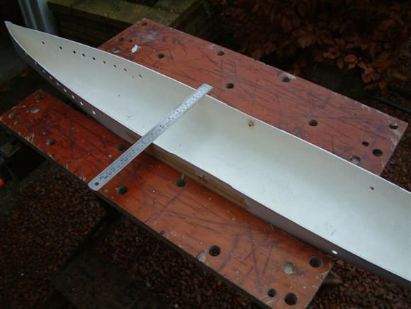
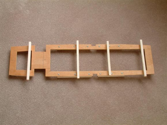
Additionally, bulwarks glued to the fibreglass hull at various points along its length would only draw the hull in to the correct beam in the vicinity of their immediate location, and the hull would tend to balloon out between the bulkheads. What was required was a plywood frame within the hull, along a substantial part of its length, to keep its width to the correct beam of 6 1/2ins. Again I used the same 4mm plywood from which I had made the motor mount and hull baseboard. I decided to use my well used workbench to hold the hull into its correct beam width, while I traced the outline of the hull onto the plywood. I placed the hull between the open sides of the bench and brought them slowly together until the beam of the hull amidships measured the required 6 1/2ins, Photo 22. The fact that the hull was flat bottomed over most of the amidships section helped to ensure that it didn’t warp during this operation.
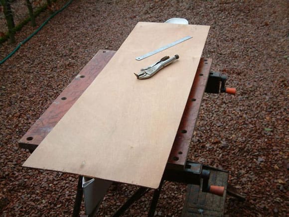
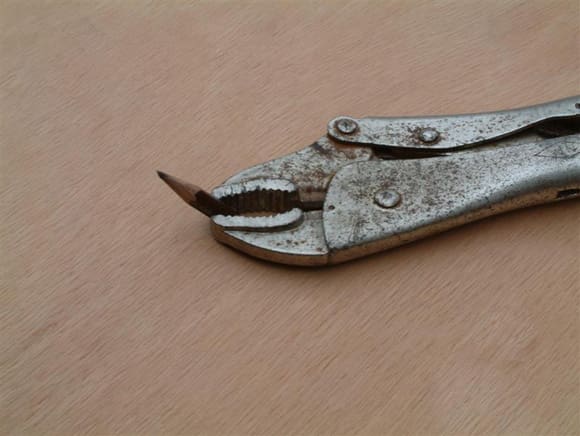
When I was satisfied with the hull width, I placed the sheet of plywood that I was using on top of the hull, and traced its outline on the underside, Photo 23. Due to the restricted space between the plywood and the top of the workbench, I had to use a piece of cut-down pencil held in a pair of footprint grips, Photo 24.
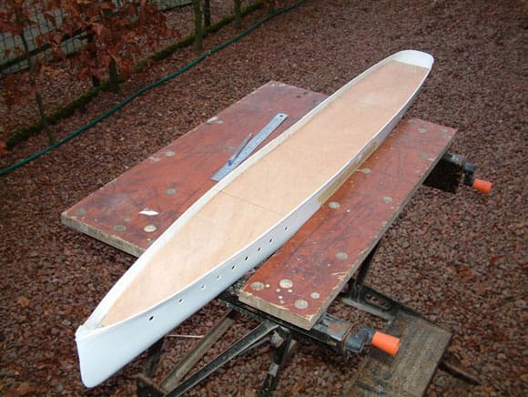
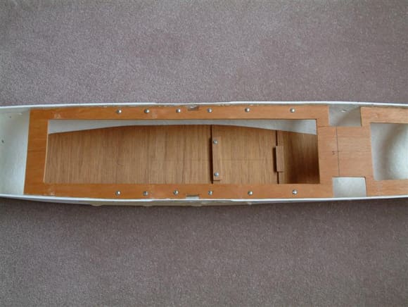
I then cut the ply, about 1/8in inside of the outline, to allow for the hull thickness, with a power jigsaw. After some trimming and sanding the piece that I had cut out was able to be dropped into the hull, and fitted snugly without distorting it, Photo 25. I then cut the ply into two pieces at a point 17ins back from the bow and the front piece was laid aside for possible use later in the build. The larger rear piece was cut to the shape shown in Photo 26. The two cut-outs near the stern were to allow access to the portholes in the hull at this location for the Marchioness of Breadalbane. They are not needed in the present model, so can be omitted. The picture shows the frame with the motor mount being used to check that it would indeed be able to be removed!
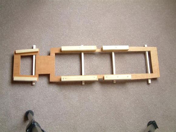
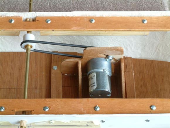
It was obvious that the frame should be positioned as near to the top of the hull as possible and I decided to place it 1/4in below the top of the hull. I was certain that the surface area of the 4mm plywood would not be sufficient to ensure a good bond to the hull so I added pieces of 3/4in square softwood, glued and screwed to the underside of the frame, Photo 27. Pieces of 1/2in square balsa were glued to the remainder of the underside of the frame. To assist the accurate positioning of the frame, I tack glued strips of 1/4in square balsa across the width of its topside. These had further strips of scrap balsa glued on top of them so that the frame could be suspended within the hull as work progressed, Photo 28. Although the completed frame would be glued in place with two part epoxy glue, I also decided to use screws through the sides of the hull. They would be behind the paddle boxes and wouldn’t be visible on the finished model. This may seem to be a bit excessive to some, but I consider it to be good practice. The last thing you want is the model coming apart after a couple of years! Photo 29 shows the location of the screw holes in the hull. After pilot holes had been drilled through the hull into the 3/4in softwood on the bottom of the hull frame, the masking tape was removed and the holes drilled out to slightly over the screw diameter. The next stage was to glue and screw the completed frame into the hull, which was a relatively straightforward job, Photo 30. I then glued the hull baseboard in position after checking that it was level by measuring down from the hull frame at both sides of each end. The paddle shaft bearings were placed in the hull, and with the paddle shaft inserted between them to ensure accurate alignment, glued in position. Photo 31 shows the motor and drive train installed in the hull.
This concludes Part One of the build. I know that my description of some of the stages of the build will probably be a bit long winded for some readers, but they are for the benefit of relatively inexperienced modeler.
Parts List
Parts beginning J are from Graupner
Parts beginning J-RB are from Robbe
Portholes J-RB1428
Narrow Companionway J-RB 1328
Wide Companionway J-RB 1327
Running Lights J-0687/25
Wheel (Corel) R123
Ships Bell (Jotika) B29
Bollards 18mm J-0301/2
Anchor J-0341/4
Bow Capstan and Chain Pipe are from Waverley Models, 20B Moor Lane, Clevedon, Somerset, BS21 6ES. Phone 01275 546772 daytime and 01275 791522 evening. Waverley Models can also supply more accurate period scale fittings for the model for scale specialists.
Handrail Stanchions are from James Lane (Display Models), 30 Broadway, Blyth, Northumberland, NE24 2PP Tel. 01670 352051.
Hull is from Metcalf Mouldings, 1 Wentworth Cottages, Haultwick, Dane End, Nr. Ware, Herts, SG11 1JG Tel: 01920 438686.
Cowl Vents – Small P-04, Large P-03 are from Reade Plastics, tel. 01606 871170. Email address www.readebusiness.com.
Lifeboats and buoyancy seats from Quaycraft, 73 Chambercombe Road, Ilfracombe, N Devon, EX34 9PH.
Drive motor system from Model Motors Direct, Keepers Cottage, Home Farm, Irwerne Minster, Dorset, DT11 8LB.
Alternative drive motor System – MFA Mini Olympus Gearbox, Part No. 1091/2. MFA Como Drills motor, Part No 456-RE385.
Evergreen plastic strip, can be purchased from most railway model shops in various sizes.
Small parts used later in the build will be fully described in the next few issues. Series to be continued next month!

