TONY DALTON converts this Italeri kit to radio control
The challenge
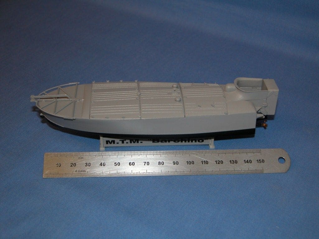
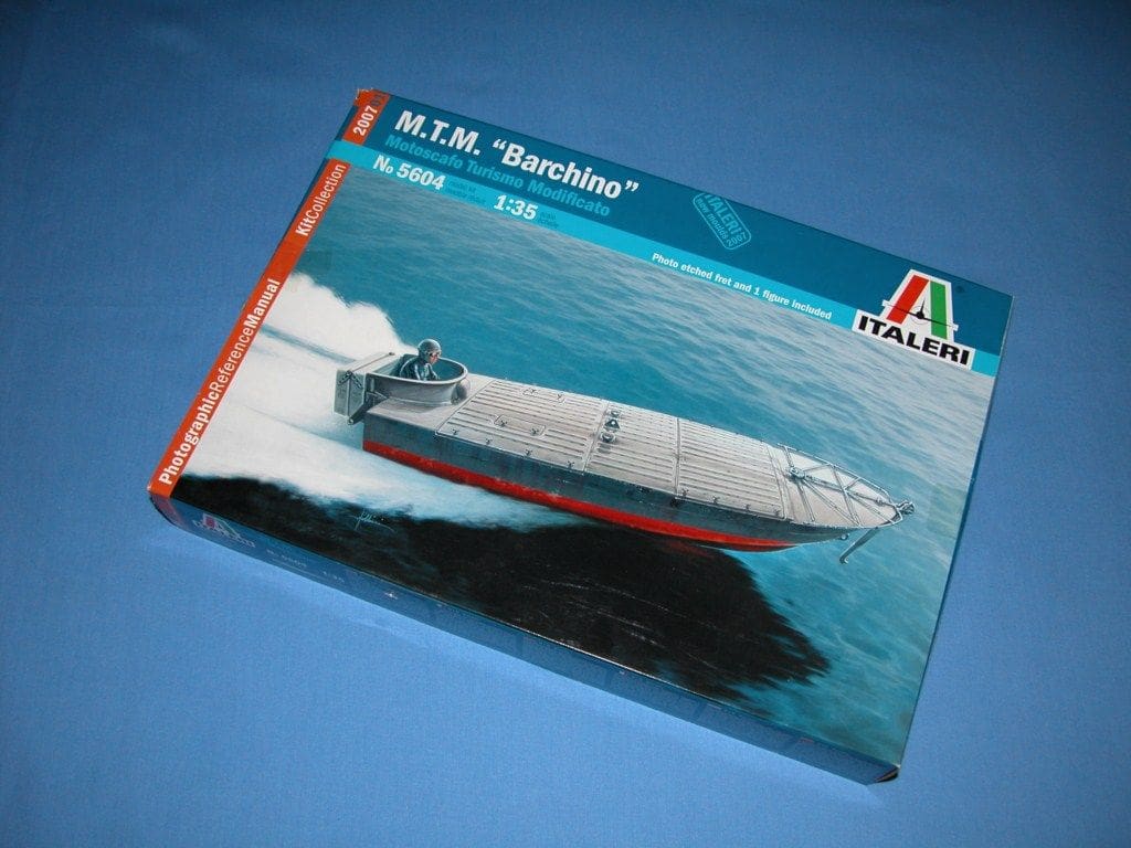
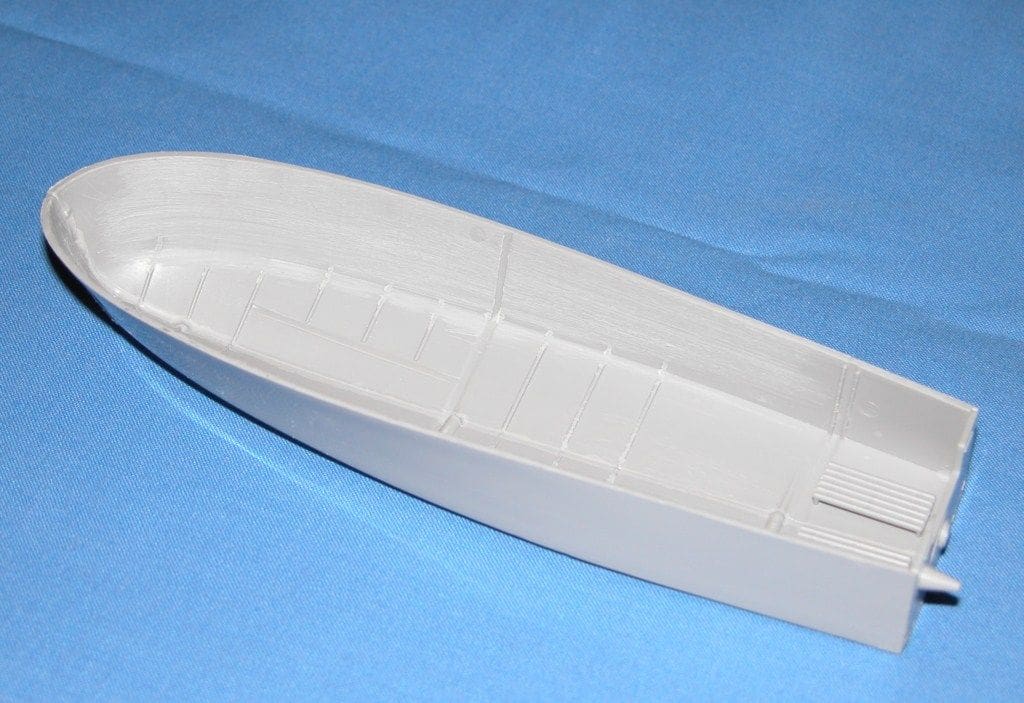
I won this Italeri kit in a 2008 Christmas raffle, Photo 1, and the completed 1:35 scale model is not much over 6 inches (150mm) long. In the process of picking up the prize, a colleague jokingly suggested that I should adapt the kit for radio control. To me that sounded like a challenge and so this article traces the story behind the design and build of my radio controlled version of MTM Barchino.
Enjoy more Model Boats Magazine reading.
Click here to subscribe & save.
A bit of history
MTM Barchino is a modified Italian tourist speed boat, conceived between 1936 and 1942. In theory the pilot would aim his craft, loaded with explosives and travelling at maximum speed, at an enemy ship. The pilot would then eject backwards into the water onto a life raft about 100 metres from the point of impact, allowing the vessel to carry on, hit the target, detonate and all with no injury to himself!
The kit
This comprises a moulded frame containing 44 grey detailed plastic parts, a figure (the pilot) and a brass photo etched sheet containing 40 parts, 30 of which are tiny butterfly wing nuts. The box also contains a reference manual with some MTM historical photos, assembly instructions and a large printed card of the box art.
The radio control design
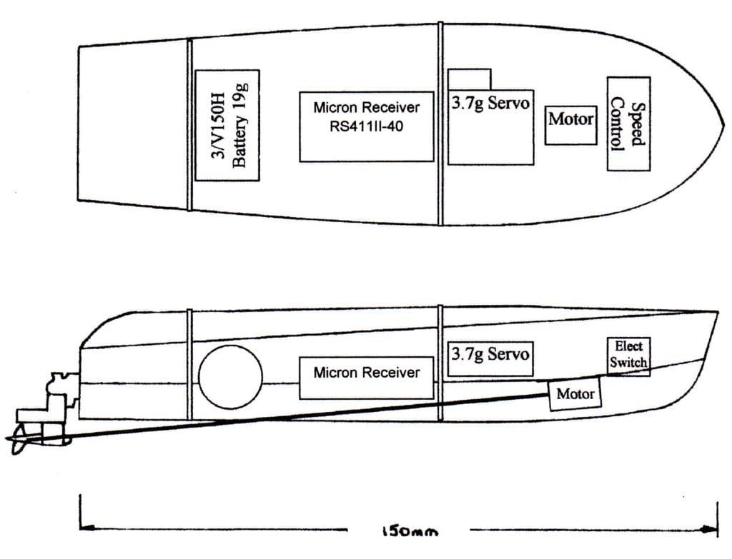
The initial task was to find suitable r/c items that were not only small, but light and reasonably priced. After browsing the Internet and discussing the requirements with friends, I eventually created a drawing of the boat which shows the outline of the selected r/c parts within it, Photo 2.
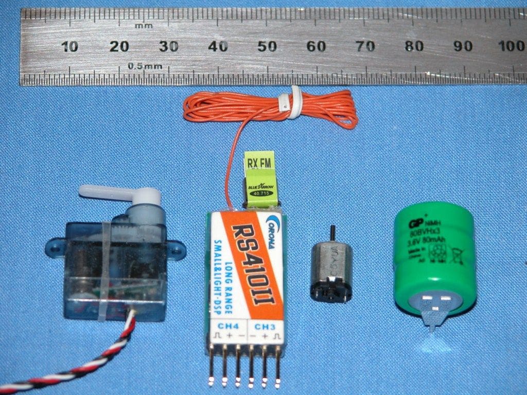
Details of the parts are listed here and some are also shown in Photo 3.
Receiver: 40MHz Corona RS410II (Micron Radio Control).
Rudder servo: Micro Servo 3.7gm (Steve Webb).
Motor: 10mm Micro DC Motor 108-101 (Precision Micro Drives).
Speed control: Home build electronic switch (forwards only).
Power source: 3.6v 80mAH Type GB80BVH (Budget Batteries).
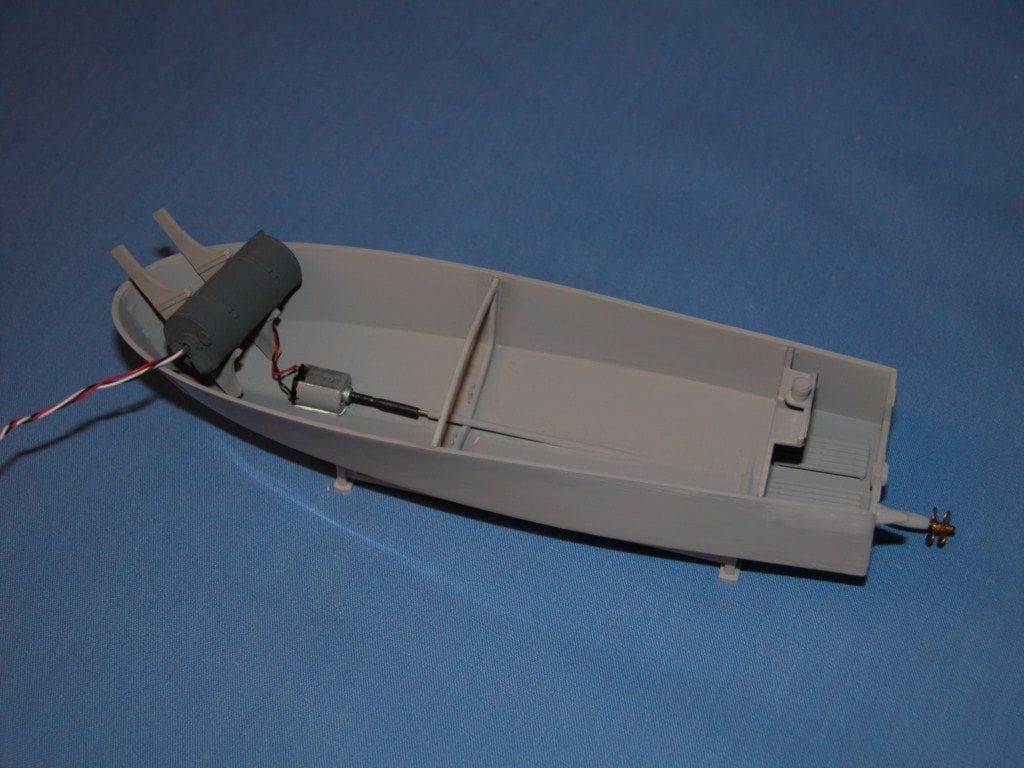
Hull layout and displacement
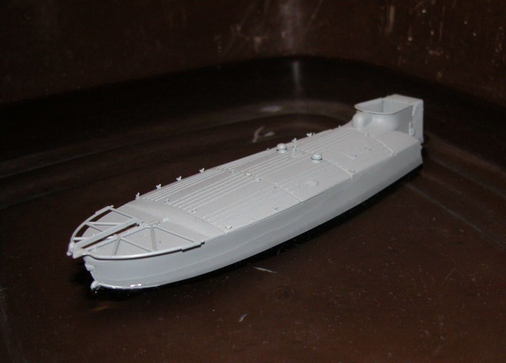
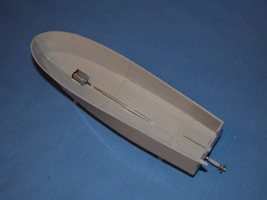
To determine the internal layout of the r/c parts within the hull it was necessary to assemble and bond the two halves and stern mouldings of the hull. Then, in order to make the hull as light as possible the inside was sanded down to remove the internal ribs. Photo 4 shows this process partly completed. The two bulkheads were then fitted and held in place by small pieces of masking tape. The r/c items were then placed into the hull and the complete assembly placed into a bowl of water, in other words the ‘test tank’. After adjusting the position of the parts, a satisfactory arrangement was determined without the model sinking. However, although it was floating in the water okay, it was deeper than its intended waterline, Photo 5.
Receiver and servo weight reduction changes
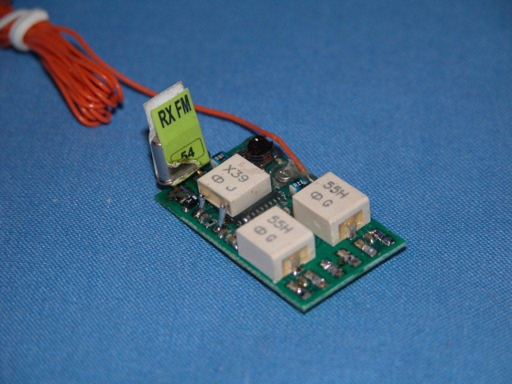
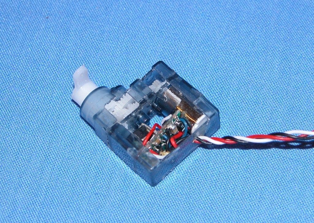
Looking at the receiver it was evident that by removing the covering sleeve and the Xtal and servo connectors, the unit could be reduced in weight as the Xtal, servo and switch would be wired directly to the receiver. These changes were implemented and reduced the weight of the receiver, Photo 6, from 4.8 to 4.0 grams, a magnificent 17% reduction!
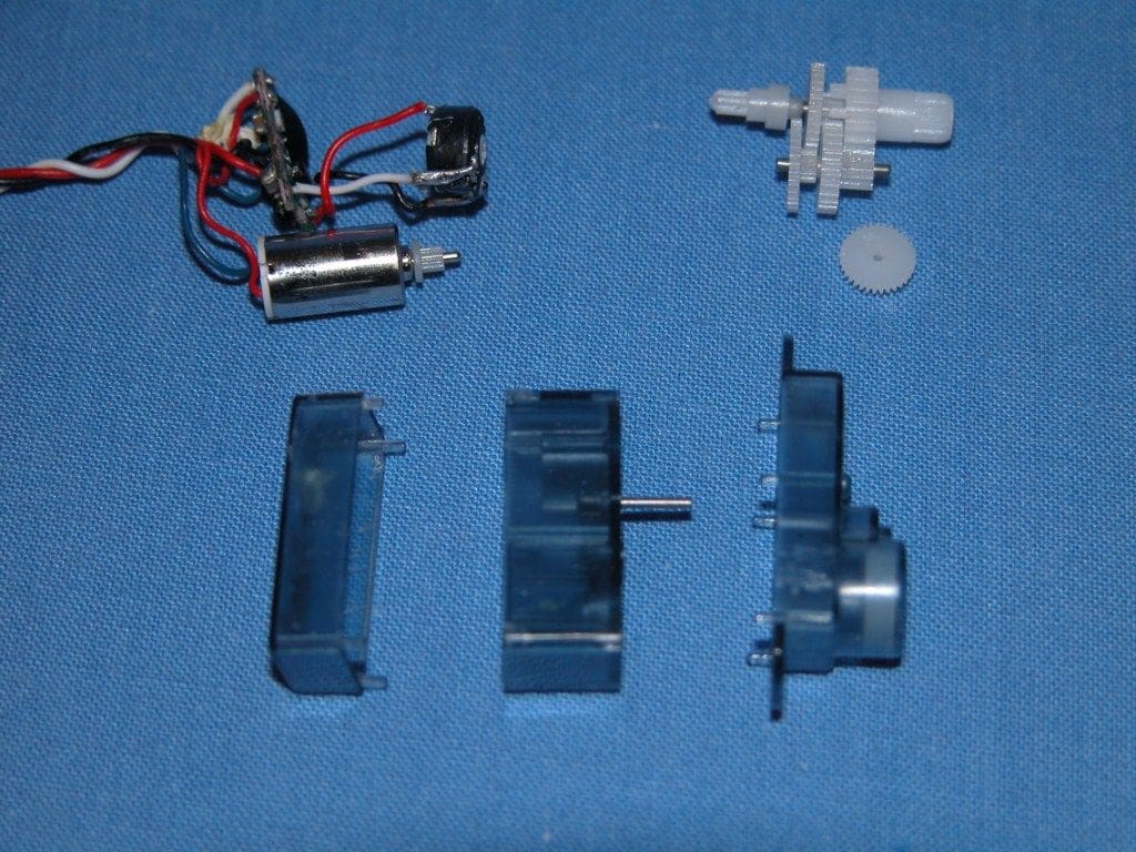
The servo modifications were more difficult as this entailed machining away part of the servo casing. Photo 7 shows the servo stripped down, awaiting modification. After cutting away the servo case and shortening the servo horn, the gearbox and motor were reassembled, Photo 8, all of which reduced the weight from 3.7 to 3.2 grams (a 13% reduction).
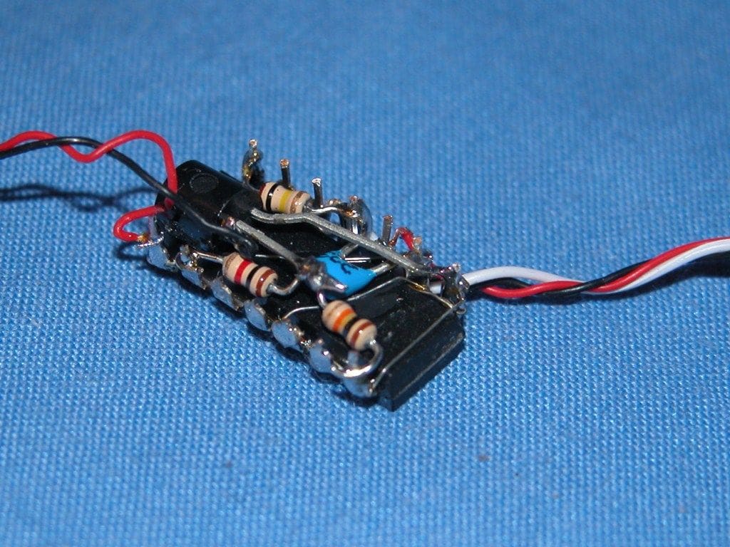
Electronic switch
An electronic switch was to be used to control the power to the motor for ahead direction only. It comprises an integrated circuit, transistor and four other small components. Normally all these components would be mounted on a printed circuit board, but this would have added additional weight, so it was therefore decided to build the switch with all its components mounted across the integrated circuit pins. Photo 9 shows the completed switch.
Propulsion system
The real boat is driven by a six cylinder internal combustion engine driving two contra rotating propellers via an outboard Z-drive unit which would be a bit tricky to replicate on this model! I therefore considered three options:
1) Jet drive system.
2) Propshaft with the propeller set behind the outboard Z-drive.
3) Propshaft driving the bottom half of the Z-drive, using the propellers supplied with the kit.
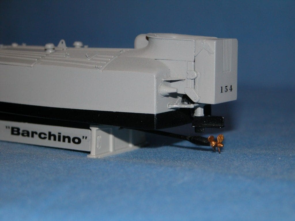
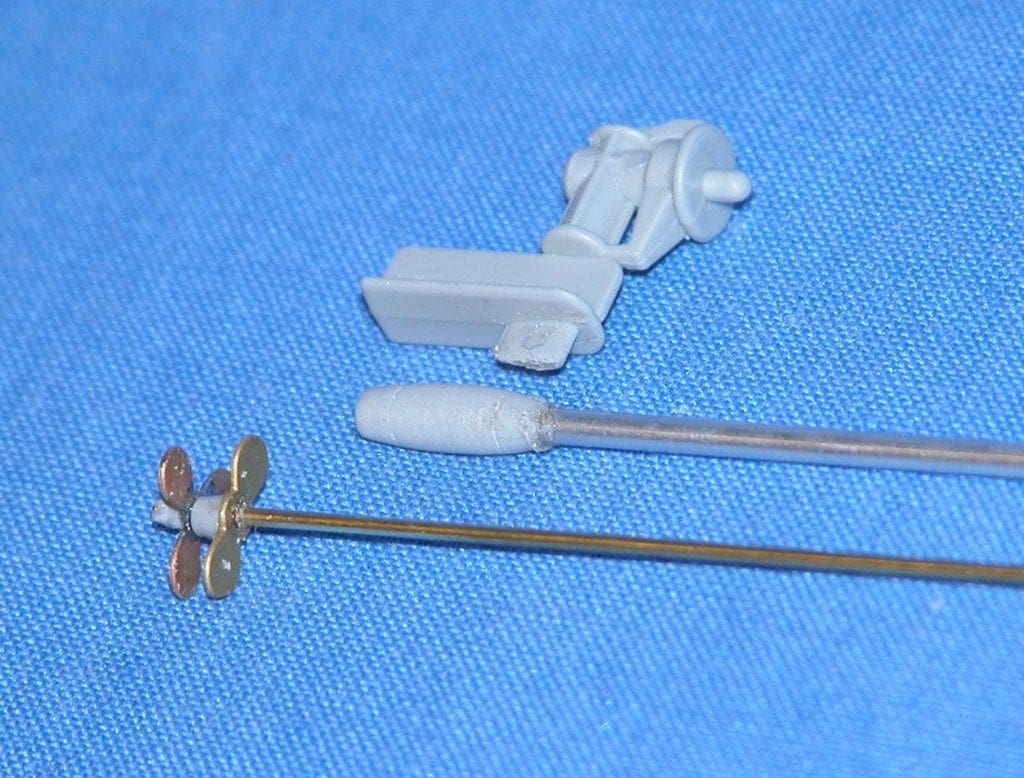
After some consideration I selected the third option. To achieve this, it was necessary to remove the bottom section of the Z-drive casing from the moulding and drill it out to accept the propshaft tube, which was to be a length of 1/16 inch diameter aluminium tube. A piece of 0.8mm diameter brass rod was used for the propshaft itself. The propellers, as supplied with the kit, were soldered/bonded directly to one end of the shaft, Photo 10. It will be observed that no pitch has been applied to the propellers at this stage.
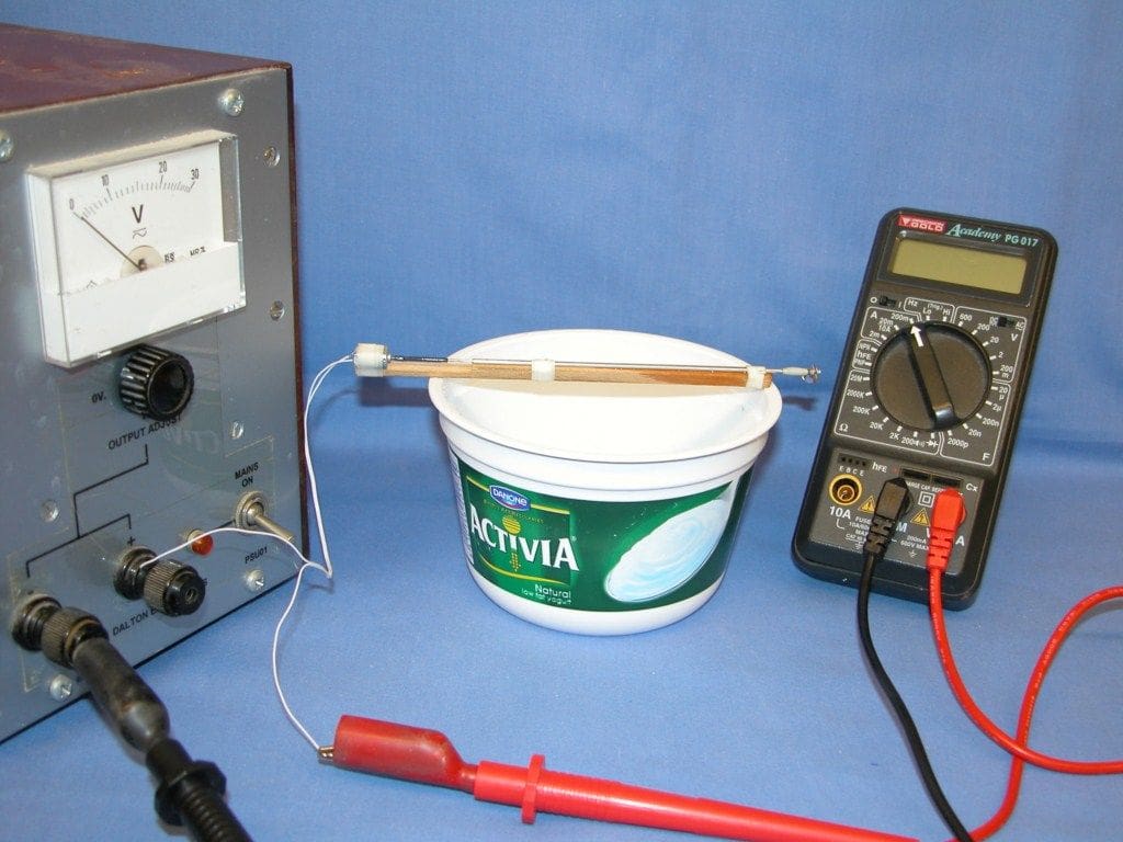
Before fitting it in the hull, I decided to test the motor and propshaft combination to ensure that the motor was of sufficient power to drive the propellers. A piece of wood was used as a jig to which it was all strapped. The propeller blades were bent to give a pitch of about 45 degrees and then, using a piece of heat shrink tubing for the coupling, power was applied to the motor, whilst immersing the propellers in water. The motor current was monitored during this operation, Photo 11, and there was no indication that the motor was overloaded and the current was found to be about 140mA which I considered to be very acceptable.
The hull was drilled to accept the propshaft tube and the bottom of the hull was lightly sanded to remove any glue lines and blemishes before bonding the tube into position. The propellers at the end of the shaft were aligned with the Z-drive moulding (which had been temporarily fitted to the stern) and the motor placed (but not yet fixed) on to a styrene mounting plate which had previously been bonded to the bottom of the hull and aligned with the propshaft, Photo 12.
Rudder system assembly
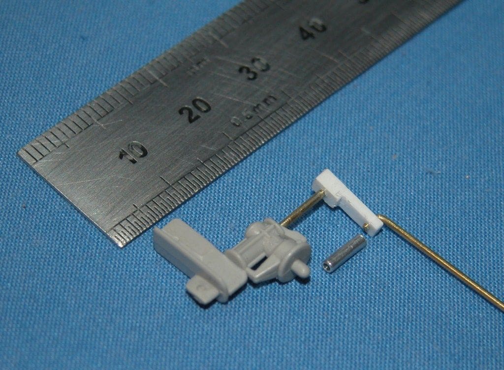
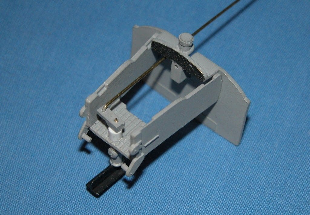
Steering is achieved by rotating the upper section (the rudder) of the Z-drive unit in a small arc. To accomplish this, the drive was modified to allow it to pivot about its axis. The moulding (Part No. 21) was held vertically in a vice, then drilled and tapped 1.0mm to a depth of about 5mm through the centre of its axis. A rudder shaft was made from a piece of 1.0mm diameter brass rod and 9mm long, which was threaded at both ends and screwed into the rudder assembly. The drive boss was then separated from the Z-drive and bonded in position on the stern of the hull. A short piece of 1/16in aluminium tube was drilled out to 1.0mm to act as a rudder shaft guide (bearing). This bearing together with a small support spacer was fitted into a hole that had been drilled in the rear cockpit seat (Part No.16) in line with the rudder shaft axis and bonded into position. The rudder shaft was then inserted into the aluminium tube and a small plastic tiller arm bonded to the top of the protruding shaft. A link from this arm passes above the floor of the cockpit and through the bulkhead (below the control panel) to the servo within the hull. The individual components are shown in Photo 13 and the trial assembly of the steering system is shown in Photo 14 prior to being fitted to the hull. The plastic steering linkage as supplied with the kit was then bonded into place on the stern bulkhead in a fixed position, but was not attached to the Z-drive.
Explosive canister assembly
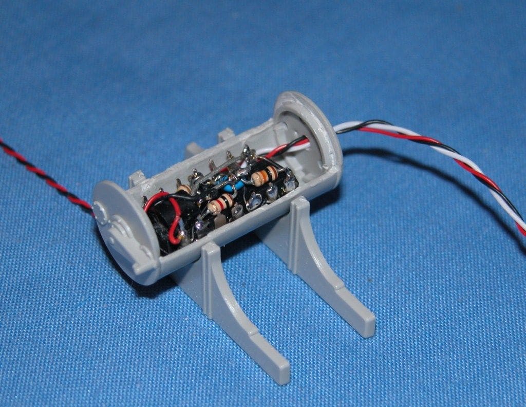
The explosive canister comprises two supports, two barrel halves and two ends. First, the two ends were glued to the lower barrel section, then small holes were drilled into the bottom and one end to allow the connection wires of the electronic switch to pass through it. The switch was then placed inside the bottom half of the assembled barrel, Photo 15. The top half of the barrel was then glued into position and the barrel painted (Tamiya XF-24). Once dry, it was bonded to its two base supports.
Painting the hull interior
Before finally fitting the r/c parts into the hull, the interior and bulkheads were all painted. The colour chosen was Sky Grey (Tamiya XF-19) similar to that shown in the booklet supplied with the kit, although the kit instructions call for a wood finish. The forward bulkhead was then glued into the hull. The wires from the explosive barrel were connected to the motor and the motor was now secured into position on its plasticard base, using a very small amount of water based sealant. A short length of heat shrink sleeving was used as a flexible coupling between the motor and the propshaft, Photo 16. The foredeck was then bonded into position on the hull.
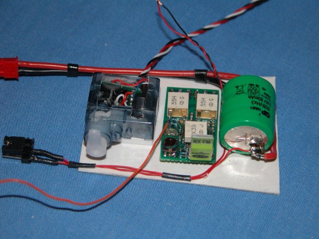
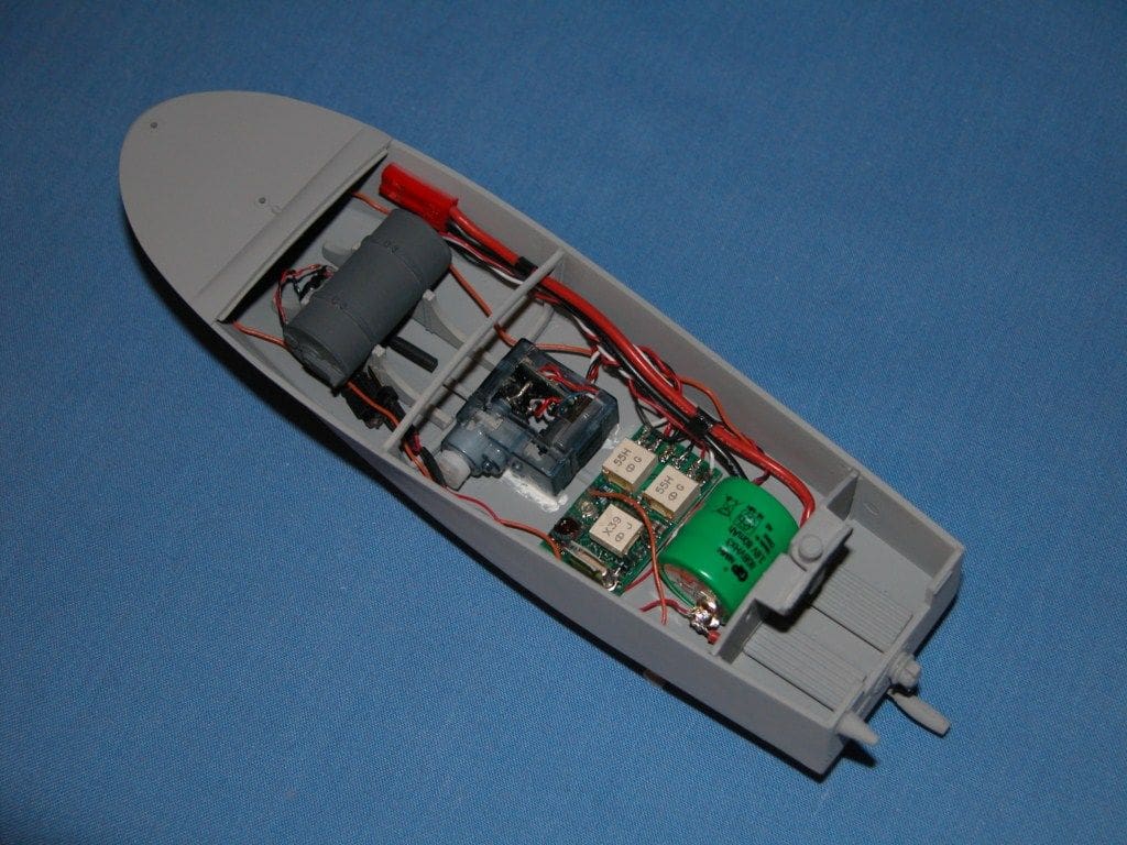
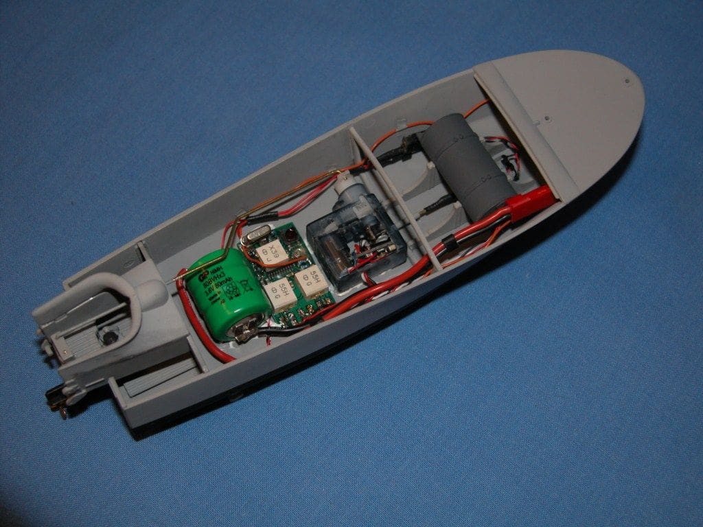
Final r/c fitting and wiring
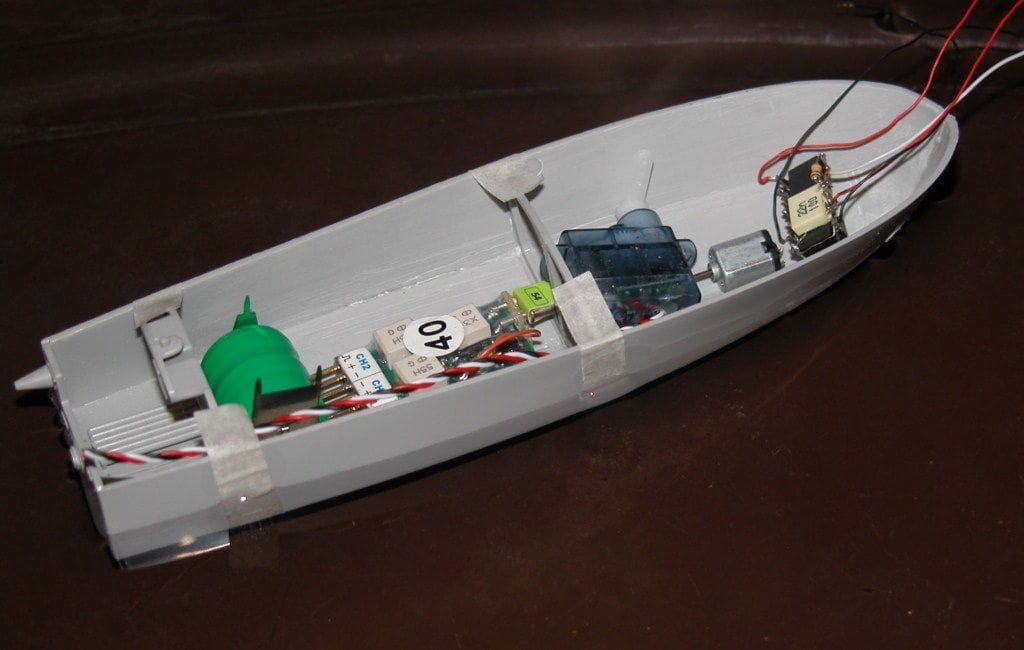
The servo was mounted on two spacers so that it could be positioned above the propshaft assembly, then in order to avoid damaging the plastic hull whilst using a soldering iron for the wiring, a simple jig was constructed using cardboard and double sided adhesive tape. The battery, radio receiver and servo were placed in their respective positions on the jig which held them in place during the wiring operation, Photo 17. Having wired all the items together, including an on/off jumper connection and a charging lead for the battery, all the items were removed from the jig and placed in the hull being secured in position using a water based sealant, Photo 18. With everything wired together and in place, it was time to put the electronics to the test. Switching on the transmitter and receiver and joy-of-joys, everything worked!
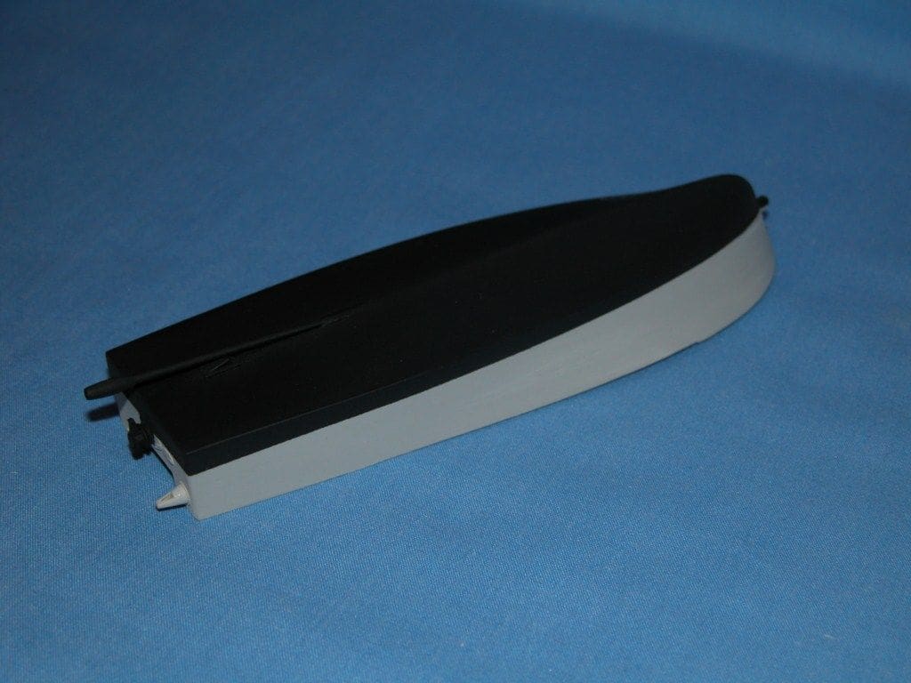
Painting the hull
It was decided to paint the hull at this point in time, as it would be difficult to gain access to the stern area once the cockpit and rudder assembly had been finally fitted. The inside of the hull was masked to prevent paint ingress and the hull painted Sky Grey all over. The upper part of the hull was then masked and the lower half below the waterline painted black (Tamiya XF-1), Photo 19.
Final assembly
The next step was to build the cockpit. The sides and base were bonded together and fitted to the aft bulkhead together with the gearbox drive moulding. The rudder actuator and push rod was fitted, having drilled a small hole in the bulkhead for the push rod to pass through. The complete assembly was trial fitted to the hull and the push rod formed into its final shape to connect the servo horn. The servo to rudder linkage was checked to ensure it functioned correctly and then the whole assembly was bonded to the hull, Photo 20.
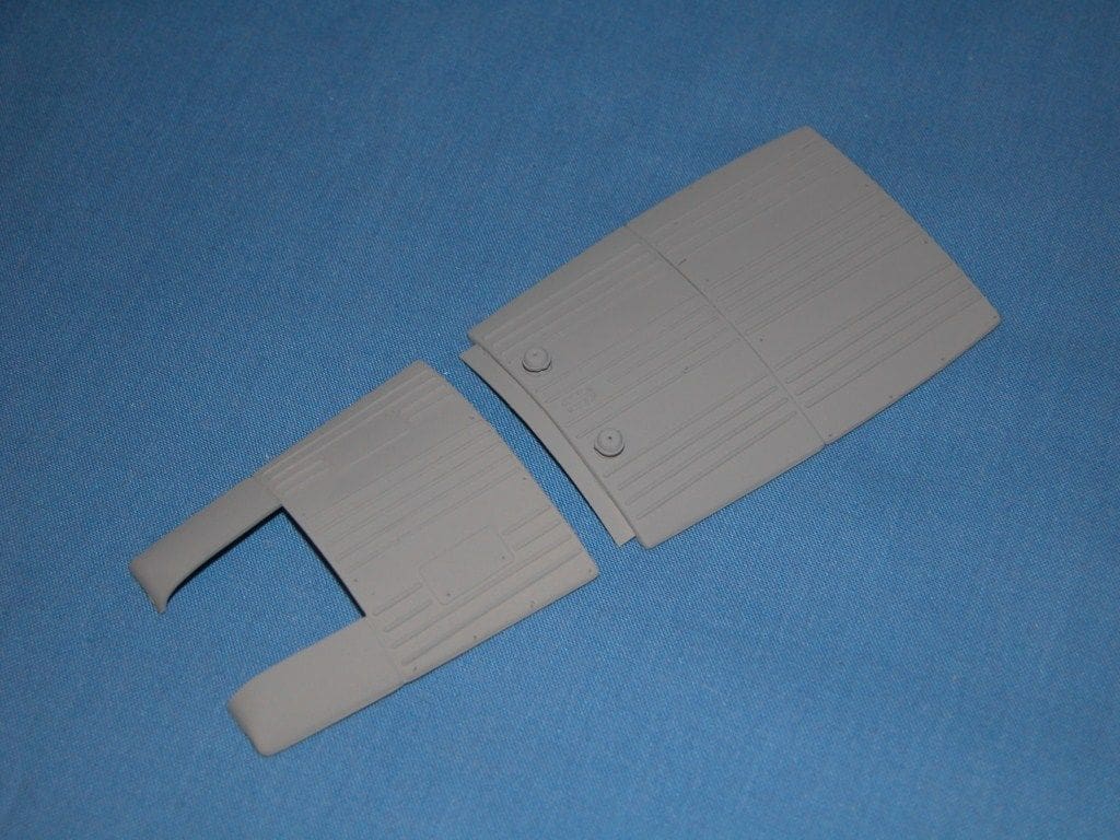
In order to allow greater access to the r/c installation, the aft deck was modified by cutting it at the joint line between the deck and rear cockpit section and a small lip from thin styrene card added to the joint area. The front hatch and cut-away rear deck were then bonded together to form one large access hatch, Photo 21, which had a retaining screw added in its centre by bonding a small piece of styrene card to the top of the centre bulkhead which together with the hatch was drilled and tapped 12BA with a cheesehead screw inserted to retain the hatch in position.
A lifting eye and all the butterfly nuts were glued to the deck and after painting, the rear deck section and cockpit sides were also glued into the hull.
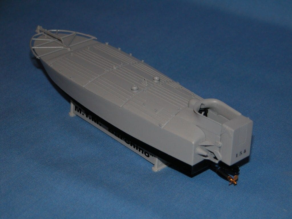
Final painting
The complete model was masked below the waterline and around the cockpit area and a final coat of Sky Grey paint was applied to the complete upper deck. The flotation cushion with etched brass fittings, steering wheel, palmola and baffo were all painted and fixed into position. Decals where added as appropriate thus completing the model which has an all up weight of just 57 grammes, Photo 22.
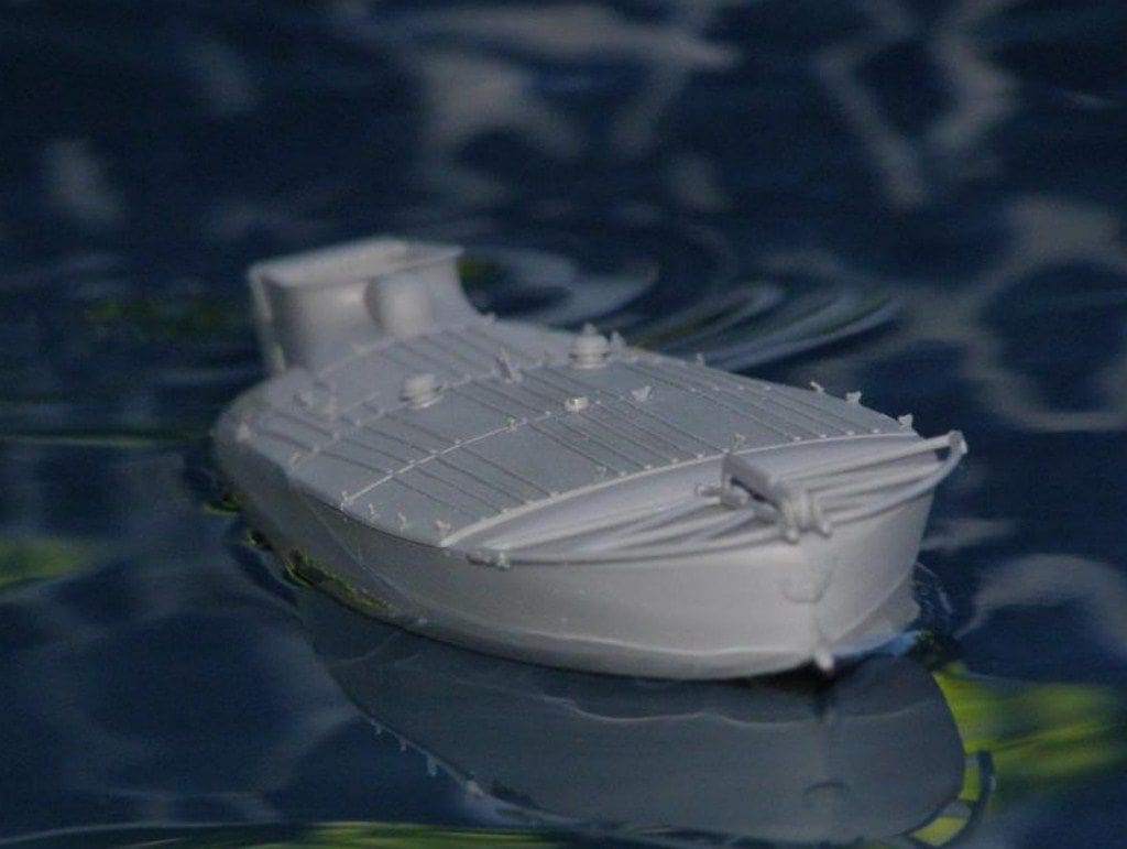
Testing
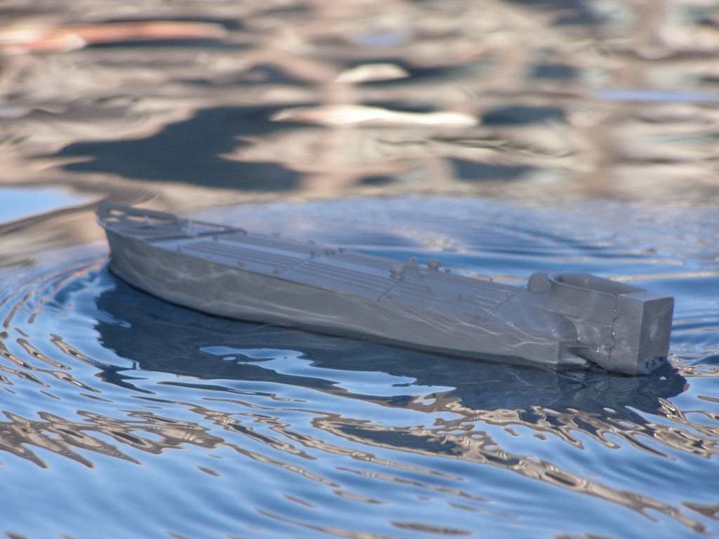
It was now completed, except for the pilot, which was a pity as he was moulded as a standing figure and would have looked better sitting in the cockpit. However I may use him later on, should I decide to create a diorama for display purposes. So the first proper on the water test was on the small pool at the September 2010 St Albans Model Engineering Show, Photo 23.

Conclusion
It took me almost two years before I sat down to seriously consider what needed to be done to build this as an r/c controlled model. I found it an enjoyable challenge that stimulated the mind as I resolved the problems encountered during the design and construction of this model. It is not the sort of model that one takes down the local lake on a regular basis (if at all!) but it does attract attention and stimulates conversation regarding its design and construction.
(Addendum: The motor listed in this article is no longer available from Precision Microdrives except in bulk quantities (1000+). A suggested alternative is P/N 110-101)