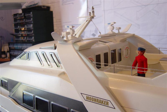
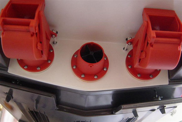
Pic 01: Cabin deck detail. Pic 02: Underside of hull just painted. The original vessel was completed in 1992 and its top speed of 124 km/h made it, at the time, the fastest Mega Yacht in the world. The yacht was designed by Frank Mulder of the Mulder Design Studio, based in Holland, who specialise in high quality motor yachts. She was built at the Ulstein Elkefjord Marine Yard in Norway and cost more than 15 million DM to build. She has a total engine power of 11,560 BHP. Enjoy more Model Boats Magazine reading. Click here to subscribe & save. Kit specificationsOverall length: 1470 mm I have outlined the kit specs. first to give an impression of the size of the task in hand should you decide to build the very impressive Moonraker from Graupner.
|
|
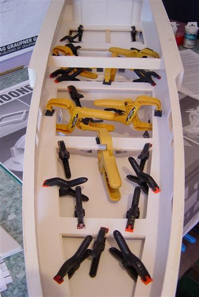
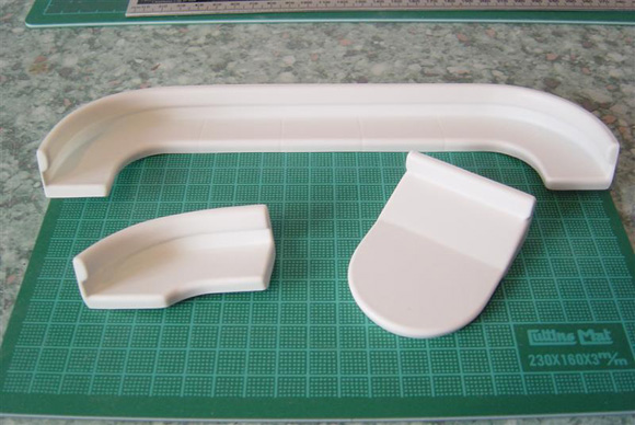
Pic 03: ‘Handy clamps’ put to good use. Initial impressionsOn the arrival of the kit the first thing that hit me was the size of the box and a certain knowledge that this project was going to be nothing but impressive, judging by the large photo on the kit box lid and the large amount of parts crammed inside. It would be easy to think that due to the numerous vac-moulded parts that the build would be quite quick but as I commenced I found this not to be the case. This is certainly not a kit for the beginner. In addition to the kit contents, as with a lot of the Graupner models, the modeller needs to purchase additional parts to complete the project, which in this case are three jet propulsion units, three motors, fittings kit, bow thruster, auxiliary and drive batteries, speed controllers, plus paints and adhesives and a few ‘bits’ (wiring, motor suppressors, etc.,) which makes a big hole in one’s, pocket but in my opinion well worth it when you see the finished vessel – very, very impressive! As with all projects it is a good idea to read the enclosed instructions and study the plans thoroughly before commencement. With Moonraker I read through everything two or three times to really get a feel of the task in hand.
|
|
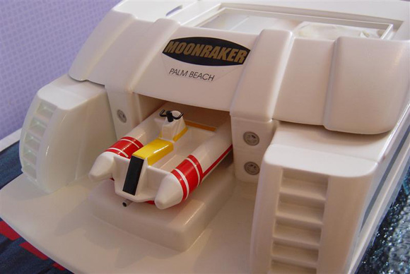
Pic 04: Aft detail showing the inflatable boat. Pic 05: Inflatable boat showing good use of ‘Trimline’. Pic 06: Rear cabin detail. Pic 07: Side view. Pic 08: View from above showing the roll over mast detail. HullThe hull is supplied as a one piece moulding with the three inlets for the jet drives pre-cut. The first job is to assemble the aft step and transom ready for the jet drive bulkheads. This assembly is then attached to the hull using two part resin, paying special attention to ensure a water tight joint/seal. The apertures for the bow thruster are also pre-cut, making the fitting of the thrusters quite straightforward.
|
|
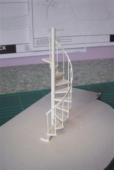
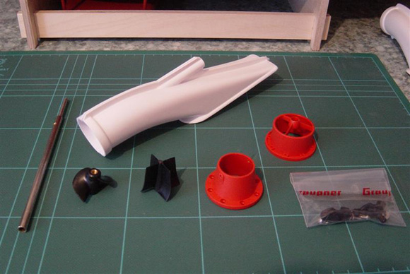
Pic 09: Spiral staircase assembled and ready for fitting. Pic 10: Close up of spiral staircase and table and chairs. Jet Propulsion UnitsThere are three of these to construct. They come with their own set of instructions and are a relatively straightforward process to put together. They work on the principle of an impellor assembly that draws in water from the inlets on the underside of the hull and propelling it through outlets on the transom underneath the rear step, so causing forward motion. Reverse motion is brought about by actuating the bucket assemblies which divert the thrust and also rotate to steer the vessel – really neat! Once initial work on the aft section of the hull is completed there came what I found to be one of the most important and crucial parts of the build – the installation of the units into the hull. It is very important to follow the instructions carefully at this stage with regard to the fitting of the impeller shafts so they do not bind, and critically pay attention to the sealing of the units to the hull inside and out. I rubbed down the areas for adhesion with silicon carbide finishing paper (my choice of abrasive available from B&Q). This is imperative to key the ABS plastic prior to gluing with two-part resin (again my choice is Stablit Express which I have found to be very reliable when a good bond is required). On the underside of the hull, once the propulsion units have been installed, I used Humbrol Model Filler to seal and tidy up the join. Only then were the inlet guard rails affixed. These stop debris – leaves, small twigs, etc., entering the units and ‘clogging up’ the system when underway.
|
|
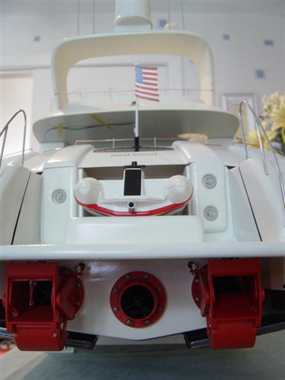
Pic 11: Business end showing the outlets and reversing mechanisms. Pic 12: Trim tab assemblies. Pics 13 & 14: Internal view showing the motors, servos and linkage assemblies. Pic 15: Alas the Captain could not find any bikini-clad beauties aboard so he drowned his sorrows in a couple of crates of beer! Pic 16: Superbly detailed aft section. Motor installationGraupner recommend fitting their Speed 700 BB motors which give adequate power on the water, but should a little more power be required they now have available the slightly more expensive Neodyme 700 series – again down to the choice of the modeller. Fitting of the motors is by way of plywood motor mounts/cradles which line up in the hull. A dry run of lining these up prior to fixing is again recommended to ensure the free running of the impellor shafts and straightness of the motor couplings. Once the shafts have been lined with grease through the lubrication tubes via bearing supports attached to the shaft tubes, and with the lower aft step of the hull complete, then it was time to submerse the rear of the boat in a shallow amount of H2O in the domestic test tank (Moonraker just fits in the bath – just!) to check if she is watertight. I would definitely do this prior to the deck being fitted as it would be very difficult to gain access to and around the jet units once the aft deck is in situ. The two reversing buckets are attached to the jet propulsion unit bulkheads later in the build.
|
|
Bow thrusterAgain straightforward as the aperture for the bow thrusters tubes are pre-cut in the hull. Once the tubes were inserted a watertight seal was achieved with my old friend Stablit Express two-part resin. The bow thruster’s motor and main drive motors are then suppressed (main drive motors are removable from the motor cradles for this purpose).
|
|
Pic 17: Overview of the aft end of the vessel. Pic 18: Close up of the upper deck. Please excuse the ‘sozzled’ Captain! Next job is the fixing of the servo tray and servos, along with the connecting rods and couplings for attachment to the reversing bucket mechanisms. The centre servo is for steering the boat, with the two outside servos actuating the reversing process. The connecting rods are sheathed in plastic tubing akin to a Bowden cable – with special attention being paid to the sealing of the holes in the transom area again with resin to ensure a water tight seal. There are quite a number of ways water could enter the hull at the rear so ‘belt and braces’ on this job. The reversing buckets (two of them) are fixed at a later stage to the two outside inlet bulkheads/manifolds on the transom underneath the rear step. They have separate assembly instructions which need to be closely followed, especially when fitting the actuating levers, but with a little care there should be no problem. Once the buckets are assembled and fixed to the manifolds the actuating rods from the servos are attached via small connectors, enabling the steering and reversing of the vessel.
|
|
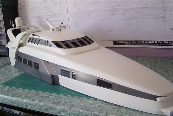
Pic 19: Vac-formed benches for the upper deck. Pic 20: Main superstructure prior to painting. Pic 21: Vac-formings at the rear prior to painting. Pic 22: Bow thruster assembly, motor wired and suppressed. Sealed in the hull with Stablit Express resin. Pic 23: Moonraker prior to painting. Pic 24: Jet propulsion outlets, trim tabs and water inlets with guard wires to stop debris entering the propulsion system. Pic 25: Double glazed doors. Main deckThe main deck is a vac-formed part which I found to be quite a snug fit when placed on the hull. Before fixing, the main deck balsa wood fillers are attached along both sides of the hull. These give sturdiness and rigidity when the deck is finally attached. One way of fixing the deck to the hull would be to use two-part resin which gives the modeller a few minutes to adjust the deck position before clamping the whole assembly while the resin cures. Alternatively, if you are really clever and confident, put the deck in place and run ‘thin’ Cyano (Superglue) around the underside of the deck, but you need to be quick as curing time is greatly reduced – if in doubt take the first option. The deck rests on a plywood frame support attached inside the hull prior to the deck being put in place. Where the deck overlaps the hull work is required to tidy up the join using filler and then sanding smooth for a nice finish. The hawse ports are then cut out and tidied up in a similar way. It is well worth putting the time in on this part of the build. Next is to fix the vac-moulded parts at the aft of the boat, rear deck walls, steps and access doors which again need filling and sanding at the joins prior to painting.
|
|
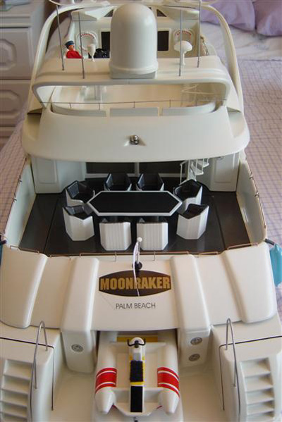
Pic 26: Main superstructure. Pics 27 to 29: Mega-Yacht complete. SuperstructureThe superstructure consists of a number of vac-formed parts with the cabin windows pre-cut, saving a lot of time and effort. Although there is only minimum internal bracing the whole assembly is quite rigid. A simple affair of putting these together was made only slightly more difficult by the cutting out of the roll over mast from vac-formed parts and affixing these to the main superstructure. I found it important to pencil mark the cut lines on these vac-mouldings, cutting back to just before the marked line and then sanding back when satisfied all is well. The upper deck also makes good use of vac-formings for the seating arrangements, sun bed and tables on this luxurious vessel. PaintingAt this point of the build I took to painting the vessel using the trusty Halfords’ car spray aerosols. A base coat of white primer to the whole of the vessel, using Alpine White gloss and Gun Metal Grey for the top coats. Personally I spend a lot of time on the preparation for painting, lightly keying the areas with a light grade silicon carbide paper, rubbing down with ‘tack cloth’ and painstakingly masking off the various areas due to receive the paint. With much patience a good result can be achieved. I use Tamiya masking tape, which gives very little ‘bleed through’, on the essential areas and normal masking tape when covering the appropriate areas with paper. Don’t use newspaper as the print will come off onto your pride and joy – use plain white paper to keep everything clean. Once the extensive paint job had been completed I applied two coats of Halfords’ lacquer and then left everything for a few days to dry and harden. After this the numerous glazed parts can be fixed, using in this case Revell polystyrene cement sparingly to fix to the cabin and superstructure. Using cyano (Superglue) causes the glazing material to ‘frost-up’ during curing and should not be used. I know this has been mentioned many times during countless reviews but do not under any circumstance mix brands of paint – grown men have been reduced to tears at the sight of the ugly marbling effect caused by mixing different brands! Fittings and fixturesOnce painting is complete the fittings can be attached and also work can be started on the small boat which is attached to the rear step. In this case the boat was first painted and then trim line used to ‘decorate’ it. For the seat I used a ‘fluffy’ strip of Velcro. At the aft end of Moonraker is a small access hatch (vac-moulding) which has a table and eight chairs attached to it. I spent quite a long time masking off these parts and spray painting them, but the effort is worthwhile. At the same time I affixed the two large glazing pieces for the sliding doors – nice part of the boat this. Other fittings such as lifebelts are placed as indicated by the plan and instructions. The railings can also be attached at this stage. I went slightly my own way with the railings and instead of soldering them together as per the instructions I used cut down brass stanchions drilled out to 1mm and then threaded 1mm brass wire through and applied a coat of lacquer – I think they look pretty good. The mast was also assembled, painted and fixed – remembering to drill the small holes in the mast base and upper cabin roof to run the wiring through for the mast lights should you wish to provide illumination. It was decided at this stage to fit two working radars. Two mini-geared motors were purchased and fixed on the underside of the upper deck superstructure directly under the radar housings – modellers’ license on this as to which way they are attached as everyone seems to have their own method. Small holes were drilled in the radar antenna and a small length of 1mm brass rod was attached to which a small length of rubber tube was pushed onto the rod and in turn pushed on the motor shaft. The radars were powered by a 6v lead acid battery which also provided the ‘juice’ for the mast lights.
|
|
Pic 30: Water jet propulsion system. Pic 31: Motors and jet units in place. ElectricsFor the bow thruster I chose to fit a small MTroniks 15 ESC powered by a 6v ‘stick pack’ type battery and three Electronize forwards only speed controllers for each main drive motor in order that each can run independently. The motors operate on 12 volts using two 6v lead acids wired in series (same amps but double the voltage). It was also decided to add a diesel sound module at this stage; a Robbe module was used and sounds pretty good. Internal hull lighting was provided by a 12v ‘courtesy light bulb’, the ones used in cars and purchased from Halfords. This was wired into the main circuit which gives a useful reminder after a session at the lake; if the lights are on you haven’t switched the power off prior to setting off back to base! Sea trialsAs always expectation is high when one has put many months into a project – and additionally a maiden voyage is always excitement tinged with a bit of nervousness – well for me anyway. There was no need to worry, Moonraker was brilliant. I set her down into the water and was immediately struck by her stability. I knew this was going to be good! I taxied her out for a few metres, using the centre motor only, and then slowly opened the throttle on the two outside motors (F14 handset with ‘twin stick’). She smoothly accelerated away with grace and speed – totally brilliant and probably the most satisfying maiden voyage for me ever. One thing though, you do need ‘acres’ of space to sail her and watch out for any weed which could be sucked in to the underside inlet ports, but only minor concerns really. ConclusionsMoonraker is a big project with a big pocket required should you wish to go the whole hog, but if Mega Yachts are your particular vice, then she is definitely the one to go for. I have since built a couple of smaller similar vessels, but nothing in my opinion quite matches the magnificent Moonraker! Till the next time – ‘Calm Seas’ to all. The kit is advertised from a number of our advertisers. Ours came through ‘A Model World’ on Tel: 01606 76513 or www.amodelworld.co.uk. Current price is around £300 for the basic kit.
|
Moonraker
Enjoy more Model Boats Magazine reading every month. Click here to subscribe.
Article Tags:

