RICHARD SIMPSON with Part Five of his six short articles on steam
Introduction
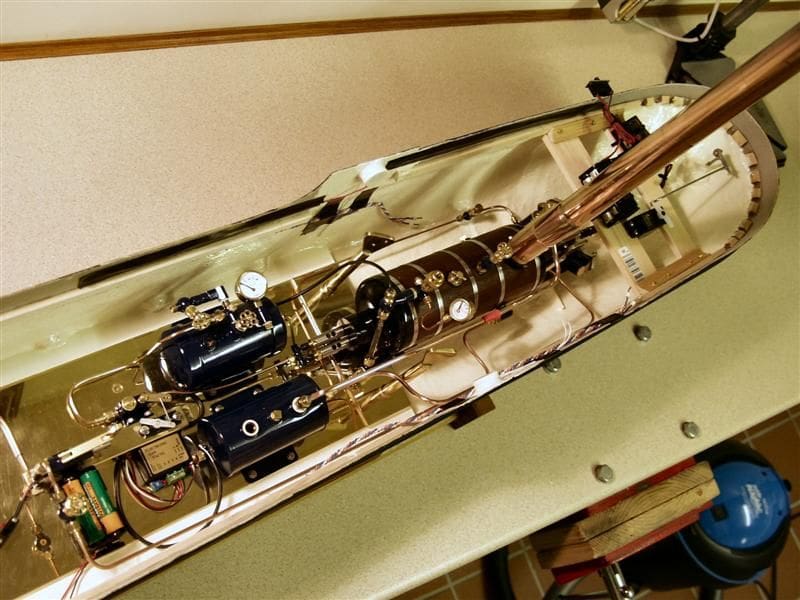
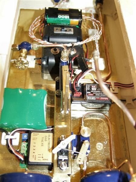
Having now had a good look at the various individual parts of the steam plant, and assuming we know into which model it will be fitted, it is time to turn our minds towards how we are going to squeeze the bits into the hull. It would be so easy to get the design wrong and end up with a part built boat that cannot be completed the way it was originally envisaged, if at all! I cannot emphasis enough the requirement to put as much time and effort as you can into how you want the plant to work, how you want the components to sit in the model, how you want to operate the plant and how you intend maintaining it. There is nothing more guaranteed to put you off steam for life that getting this wrong and ending up with something with which you are completely disheartened. Take your time, think about it, play around with the bits, change your mind, move things around and think of all the consequences before committing to a plan. Even then you will get it wrong or change your mind, but at least you will have given yourself a solid foundation to work from and changes should consequently be minimised and be only of a minor nature, Photo 1.
Enjoy more Model Boats Magazine reading.
Click here to subscribe & save.
First select the components
We are going to start off by deciding just what you want to incorporate into your model and to do that you have to make some decisions regarding how you want to operate it, what you want to do at the side of the pond and how frequently. Now you need to decide whether you want an automatically filling boiler, a manual feed from an onboard tank, a manual feed from an outside tank or a one shot boiler. Do you want to use an on board gas tank or use the tanks as purchased from the camping shops? What gas control do you want to use, if any, and what electronics do you want to incorporate such as lighting and sound systems.
Just to give you an idea of my own project, these are the decisions I made right from the start before any item was placed in the hull and before a number of them were even purchased.
1) I wanted to fill the boiler under pressure, but I did not want automatic level control. This meant the inclusion of a manual feed pump and an on board feed water tank (in the bows), Photo 2.
2) I had to use a manufactured gas tank because the purchased tanks from the camping shop would not go through the opening in the decks.
3) I was going to use a separator tank.
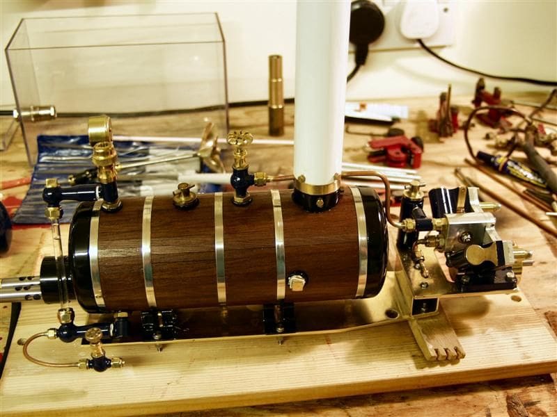
4) I needed to get the plant as far back in the hull as possible to try to get the boiler flue as close as possible to be in line with the models funnel. This meant a Vee Twin Oscillator Engine with a horizontal boiler fitted with a flue at the aft end of the boiler, Photo 3.
5) I was going to incorporate lighting around the model.
6) I expected to come into the pondside approximately every half an hour to empty the separator tank, fill up the boiler, top up the lubricator and fill up the gas tank.
Once these decisions have been made and you are happy that you are reasonably sure you are not going to change your mind, then we can progress to the next stage of the design phase.
Arranging the components
Now you need to get your hull to a reasonably completed stage. If you are building a kit and have a ready made GRP hull then you are there already virtually there, but if you are scratch building or making a plank on frame kit you need to have the hull completed. It would also be easier if you had the main decks available, but not attached, so you can see what height limitations you will have to work with as well as get a feel for your access possibilities. You should have the steam plant base in the hull, which in my case was a brass plate mounted on wooden bearers and covering steel plates which were the main bulk of the ballast.
Then, simply play around with the arrangement of the components you have decided to fit. Take your time with this because even when you are finally happy you will still think of things that you had missed and want to make adjustments. Think of how the components relate to each other, how they can be accessed, how they can be removed, how they can be operated in the boat and whether there is likely to be any effect on each other from heat or moisture. Remember that once the decks are secured in place there is considerably less opportunity to move items around, so make the most of this, Photo 4.
Once again, using my own project, these are the decisions I came to as regards the location of the main items and arrangements of the plant:
1) I wanted to put the feed tank into the bow, thereby using up less of the important amidships space.
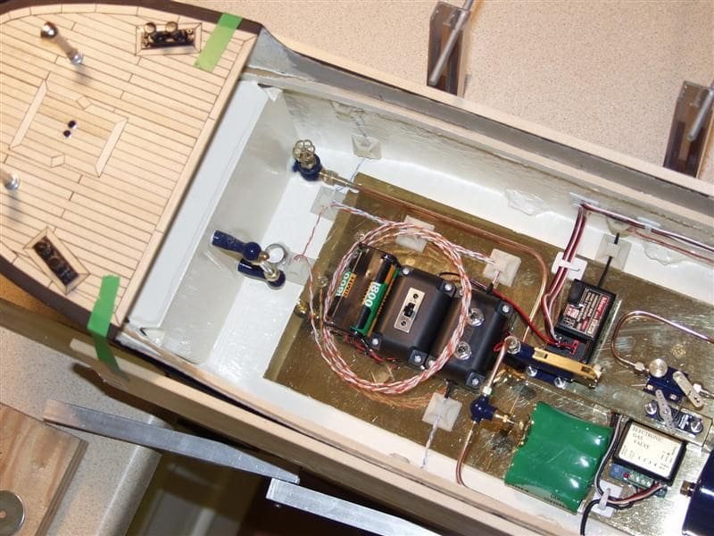
2) I wanted to place the electrics and electronics at the opposite end from the steam plant so the receiver, batteries, switches etc. were all placed in the forward hatch area.
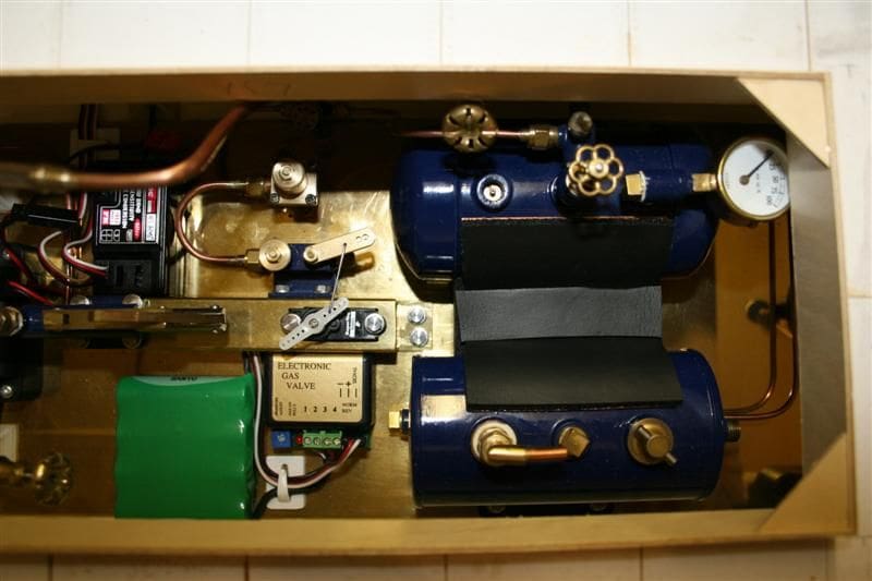
3) The water pump had to be very accessible so it was mounted on a brass square section tube bearer in the middle of the main hatch where it is easily operable with a handle extension. The brass tube bearer was then also used to mount the gas control valve and servo, Photo 5.
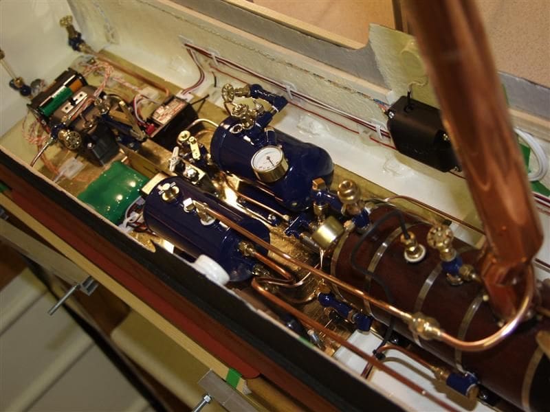
4) The separator tank and the gas tank needed to be near each other to allow for a heat transfer arrangement to be fitted between the two, so they were mounted either side of the main hatch at the aft end, Photo 6.
5) The boiler and engine assembly would fit through the aft deck access but to get it into place would prove to be extremely difficult. The best way around this was to modify the model and have the bridge assembly removable. The design of this would be finalised when the two decks were fitted.
6) The engine servo and the rudder servo would be located in the aft access hatch on a tray incorporating protection from the heat and moisture of the engine.
Once you are reasonably confident that your design is as you want it, you can then progress to putting some of the thoughts into practice.
Installing the components
At last the time has come to start to install some of the larger items into the hull. Starting with the items with very limited flexibility, the boiler and engine assembly are obviously the first. Mine are mounted on another independent brass base to make removal as easy as possible, but I had to come up with a method of fixing the base that could be released externally and secured when the unit was in place. I decided to embed machine screws into a resin floor that could then have nuts simply fitted to them when the plate was in place, Photo 7.
The gas tank, separator tank and brass square tube were all fixed to the main forward brass plate and the water pump attached to the top of it all with stainless steel machine screws. Then the arrangement of all the smaller items such as the batteries, switches, receivers and servos was finalised and they were installed, with most of these being held in place with a blob of silicone sealant, making removal relatively simple in the future.
At the end of the day I was quite pleased with the way all the items went in and the relationship with each other. The gas tank is next to the gas valve which in turn is very close to the boiler burner, so that all goes together well. The separator tank is close enough to the gas tank to enable the fitting of a copper heat sink bridge to be relatively easy and most things are easily accessible and easily removable. Your own plant will be very different to this installation, but the chances of a successful and reliable model will be greatly improved if you follow the same steps that I did. It will be almost impossible to make major changes to the installation after the decks are all fitted, so make the most of this time and be completely satisfied before you progress further.
Connecting them all together
The design stage has not yet finished as all the items placed into the model so far have all got to be connected together by either cables or copper pipework. This may seem like a simple final process, but the same care and attention must still be put into this because you still need to think of accessibility and removal of the parts. It is no good running a water feed line over the top of the boiler to then discover you cannot remove the boiler any more. All the pipes must be designed and fitted in such a manner as to allow no interference with any of the other parts and allow you to operate and maintain the model as you originally envisaged. Once again take your time, plan the pipe runs carefully and bear in mind those connections that are going to have to be broken to enable the boiler to be removed. It may look accessible until you try to get that BA spanner onto the gas connection that is now below the gas valve. Eventually it will all come together and the plant will be seated in your model, hopefully looking neat and tidy, ready to be put to its first test.
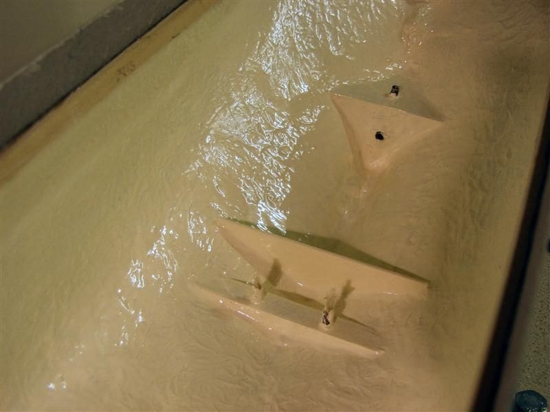
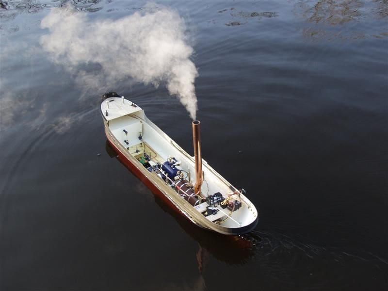
Sea trials
As with any vessel being built, the sea trials are an important part of its development, Photo 8. Not only does it prove to the owner that the model performs within the design criteria, but it also allows the builder the opportunity to make any adjustments relatively easily. With your model it is your first chance to test out the design under normal conditions and get a feel for how it operates. My first time on the water was with no decks fitted, so obviously a calm day was required, so this gave me the opportunity to see how easy it would be to operate. Could I easily access the separator tank to empty it, could I get to the engine lubricator to top it up, could I operate the boiler feed pump easily? These were all the questions for which I wanted an answer when I still had the opportunity to make modifications, before the decks were laid and the accessibility greatly reduced.
My own steam plant revealed a couple of things that could be improved, which were subsequently modified, before adding the main deck and testing the model on the water again. To give you an idea of one concern that I had, was that when I first opened up the boiler stop valve to the engine I got a slug of water through that had to go through the engine before steam would flow. This invariably leaked out from the control valve and the cylinder port faces and had the potential to damage the engine. Also the boiler was fitted with a vacuum breaker valve which was designed to prevent the boiler going into a vacuum when it cooled down, potentially drawing oily water back into it. Unfortunately the ball in the vacuum breaker seemed to stick and not work, so I decided to fit a vent line in the discharge pipe to the engine. This allows the line to be vented outside the hull before putting the engine on line and it allows the boiler to vent during cooling. Simple modifications such as this were possible as a result of the sea trials and allowed a more reliable and user friendly plant to be designed.

