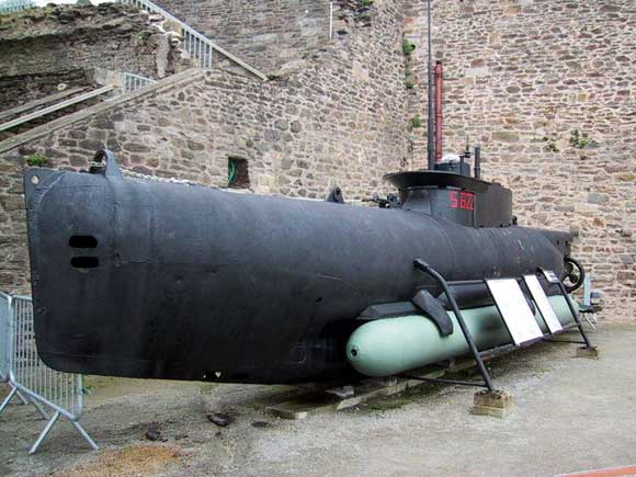
IntroductionThe Polish company GPM have recently produced four card model kits of German mini U-boats, of which the latest two are the two-man Seehund and one-man Biber submarines, each armed with two torpedoes. Both these kits were supplied for review by Marcle Models who advertise regularly in this magazine. The Biber design was based on the British submarine Welman W46 captured in Bergen in 1943. The prototype was finished in March 1944 and eventually 324 boats were delivered by two shipyards Klockner Jumbolt Deutz and the Ansaldo Shipyard Facility in Italy. The Seehund, Photo 1, was a two-man midget submarine with a relatively long range, designed by Kort Fischer and Otto Girm, and built by Howaldswerke dockyard in 1944. 285 were delivered by three dockyards, and they were the most successful of the small U-boats. Both models were built, each being constructed in a similar manner and both in a similar time of 20 25 hours. For the purpose of this review, I shall describe the construction of the Seehund, which being larger was easier to photograph, Photo 2. The kitThis card model by GPM is printed on four sheets of A4 card to a scale of 1:25 and results in a model 36cm long. There are very good easy to follow construction diagrams which are of more use than the brief English text. The bulkheads for the boat and its two torpedoes are printed on thin card which has to be thickened to 1mm. However, GPM now produce a laser cut card sheet, of the correct thickness for these parts, which can be purchased as an extra at low cost. For this review they were used and proved to be very accurate and well worth that little extra cost, Photo 3. Enjoy more Model Boats Magazine reading. Click here to subscribe & save. Tools and gluesAll cutting was done with X-Acto modelling knives which with their rigid blades, I find to be very controllable. A 60cm steel rule, a variety of rigid rods of various diameters including cocktail sticks, a sharp bradawl together with a self healing cutting mat make up the basic tool kit required. Glues used are Loctite All Purpose for the majority of the construction, Resin W, a white woodworking glue that dries clear, used sparingly so as not to over wet the card and superglue where parts had to be made rigid and for fitting very small items, i.e. propeller blades, Photo 4.
|
|
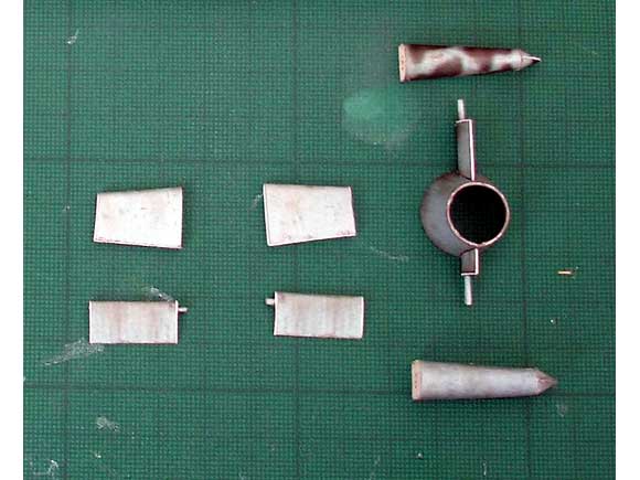
The hullIt is suggested in the instructions that the torpedoes are built first and if the builder has little experience of building aircraft and other tubular structures in card, then this is probably a good idea as it gives practice in such construction before moving on to the more difficult hull. However, the natural sequence for building this model is to construct the hull first, so I am describing that now, but there is no reason why you cannot make the torpedoes before the hull, if you so wish. Starting with the vessel, I noticed that each hull section had only one bulkhead, and that being at the aft end. For these I used the laser cut ones, but I also made up to 1mm those from the kit, and was able to use these to seal the other end of the sections, using the aft end of the adjacent section in the forward end of the next. This gave each hull section support at each end which made the sections stronger and easier to join together, Photo 5. The five bow sections were assembled and glued together to make one unit. The three centre sections were built the same way and the aft cone was built, again with a circular bulkhead at its forward end. These were then glued together and the upper and lower sections added to the tail cone, Photos 6 and 7. At this stage I added the docking keel (Part 94), which was strengthened internally with an 8.5mm strip of thick card cut from the edge of the laser cut card sheet. I also built the stand at this time so that the hull would have somewhere safe to sit. Here, the stand as printed does not look like the construction diagram, but it is quite easy to work out how it should be built. Some of the tabs have to be cut off in order for the card to follow a curve, and four of them have to be re-shaped as they are too big. It is easy to work out what you have to do, but be aware that you have to do it, Photo 8. Back to the hull: We have to build the kort nozzle, rudder and hydro-planes. The instructions indicate that you glue the inner surface of the kort to the outer surface, cut out the shape then form it into a tapered tube. On a tight curvature like this, that is hard to achieve, as the inner surface tends to ruckle up. I found it easier to cut out the two pieces together, but did not immediately join them. Then shape and glue together the outer section to the correct form. The inner section is then rolled to form a tube and then slid inside the outer section. A dry run will show it is too long and the ends overlap, but these can be trimmed off and when all is correct, the inner part glued inside the outer one. The rudder sections are formed and added to the top and bottom of the nozzle. The pivot pins for the rudder and hydro-planes are formed from card, but wire or wood could be used instead, Photo 9. Before assembling the control surfaces to the rear of the hull, it is necessary to make and fit the propeller. The boss is formed around the pointed end of a cocktail stick and the three blades glued on where marked. With the propeller in place, the nozzle can be slid over it and its two supporting arms glued to the top and bottom of the rear hull, Photo 10. The horizontal control surfaces can now be made up and fitted, firstly the fixed surfaces and then the moveable ones, with the pivot bar passing between the two through the rear hull, Photo 11. Now we come to the conning tower. Part 95 is cut out and shaped before gluing together at its after end. I now chose to fit a thin strip of card around its upper edge just below the rim. This gave a slight ledge for Part 99 to sit on and formed a stronger joint. Part 98 is formed into a square and glued to Part 97 to form a tray. Parts 120 to 126 are formed into a cylindrical chamber with a clear dome on the top which is glued on to this tray and then to the underside of Part 99. For the review, the dome was formed of card as supplied but a clear dome will be made and fitted later. Parts 100, 101 and 101a are cut and fitted to the front of the conning tower, Photo 12. Before fitting other details, glue the tower to the hull in the marked place and the front fillet, Part 96 is also applied, Photo 13. At this time I also fitted the torpedo supports (Parts 127 to 131, L&R) before fitting the periscope and antennae to the top of the tower. Finally the landing hooks are fitted to the top of the hull to complete the U-boat itself, Photo 14. TorpedoesTwo of these were carried by these boats and are supplied in this kit. The laser-cut card supplies one bulkhead for each section, but where required ones from the kit can be made up to 1mm thick and used in addition, Photo 15. Take time to form the long centre section, rolling around thinner and thinner rods until a dry run gives a perfect tube. Only then apply the glue and fit the bulkheads. The shorter units will form more easily and when all have been formed, can be glued together, Photo 16. To form the nose of the torpedo, I made a dowel rod the same diameter of bulkhead four and rounded one end to the same shape as the torpedo nose. Part 3 was then cut out and the fourteen blades rolled around a rod so that the tips bend over. The rod is then rolled along its rear edge to form it into a circle. Glue is then applied and the nose section formed around the wooden former, taking care not to glue it to the wood! The arming propeller boss (Parts 1 and 2) can be made the same way using a rod of the same diameter as Part 2. When all is dry, fit a piece of shaped wood into the nose of Part 1, Photo 17. All sections are joined together to form the main body of the torpedo. The four tail fins are made up, as is the boss of the propeller, and these are fitted to the tail cone. Finally the propeller blades for both the drive prop and the arming prop are cut out and fitted using superglue, Photo 18. Because I was also building the Biber U-boat by GPM to this scale at the same time, and both are fitted with the same type of torpedo, I had four to make and so set up a small production line which I found does save time overall. One torpedo is hung each side of the hull to complete the model, Photos 19 and 20. Final finishingAny cut card edges which show once the model is completed are touched in with Humbrol matt paints, or if there is no glue on them, by artists watercolour paint. ConclusionsAs stated earlier, GPM have produced four mini U-boats in this scale which should be very popular with submarine fans. Both Biber and Seehund have a medium difficulty rating, but I would argue that the Bibers hull is trickier to build, due to its smaller size and the way the hull is built. However, if you build Seehund first, there should be no difficulty with Biber. The GPM laser-cut parts and kits were supplied by Marcle Models, who advertise in this magazine, have a good website and can supply all the GPM U-boat kits from their comprehensive catalogue. These models are of unusual prototypes, attractive and to a relatively large scale, but small enough to be displayed easily. Price of the basic Seehund kit is £7.95 plus p/p. The laser cut parts are extra. A delight to build and something different from my usual fare of card ships and watercolour painting.
|
Mini U-Boats of the German Kriegsmarine
Enjoy more Model Boats Magazine reading every month. Click here to subscribe.
Article Tags:

