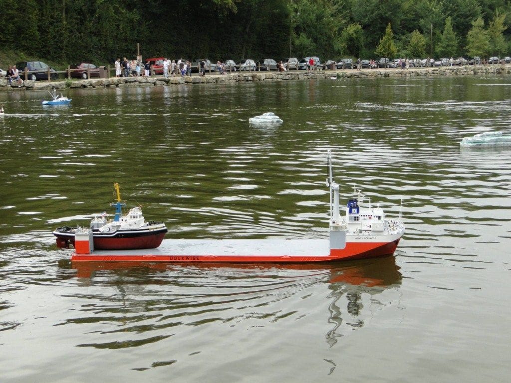
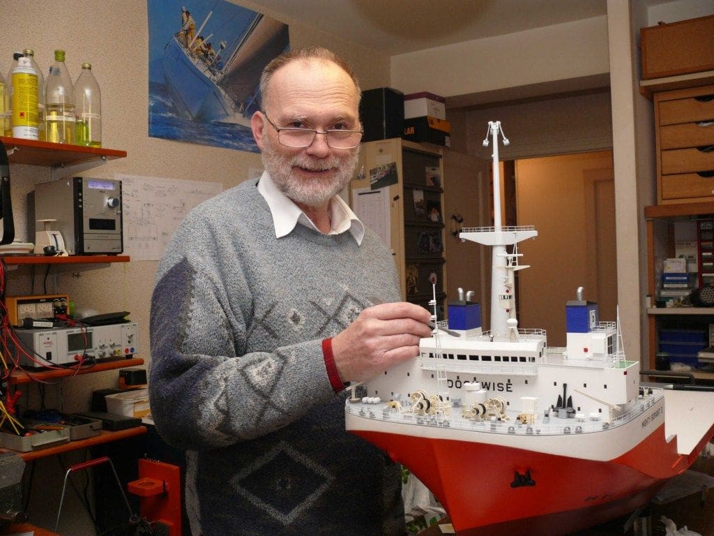
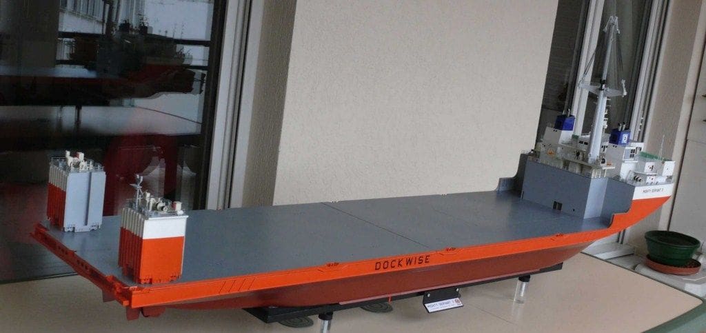
JEAN-PIERRE COURVOISIER scratch builds an amazing 1:100 scale model

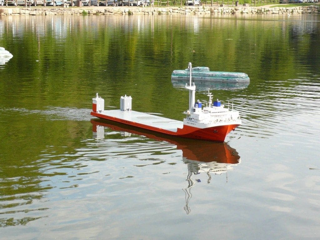
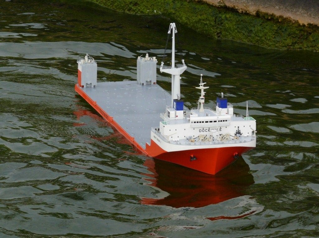
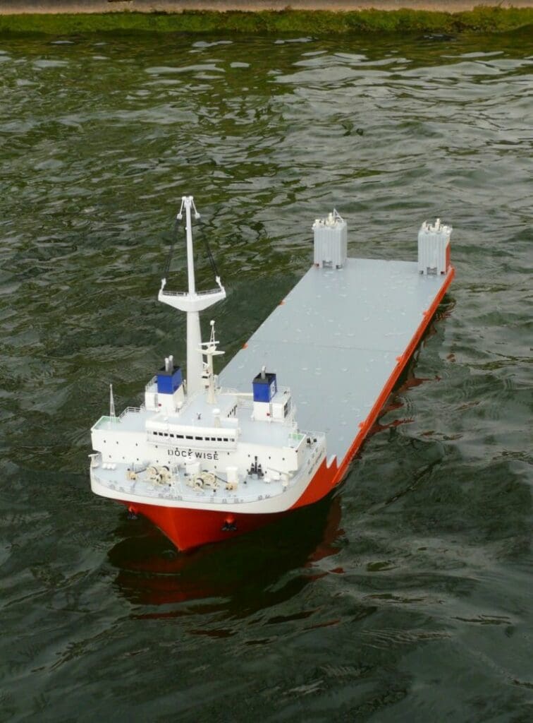
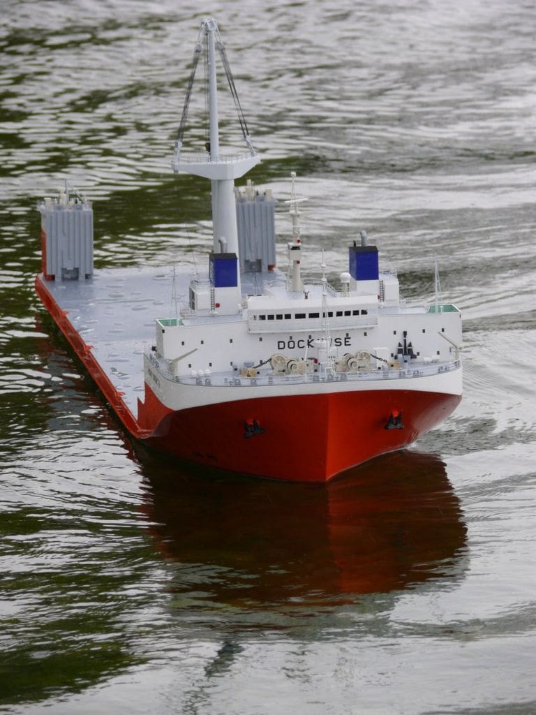
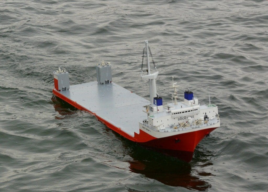
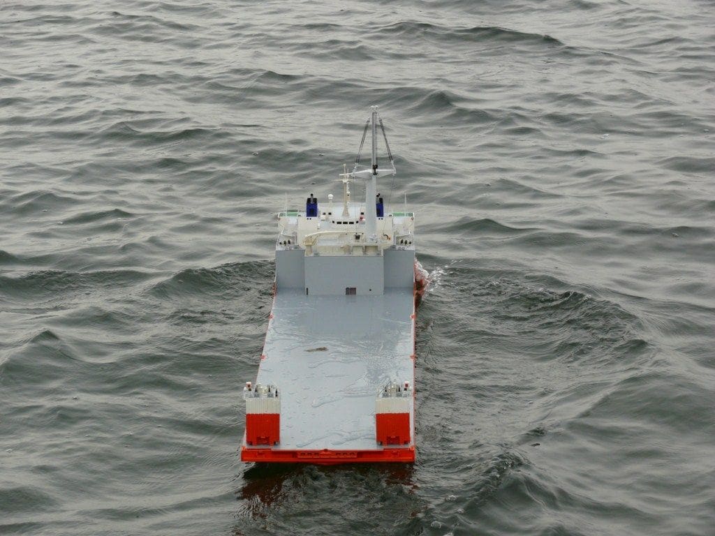
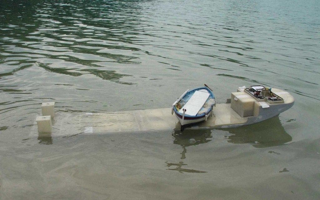
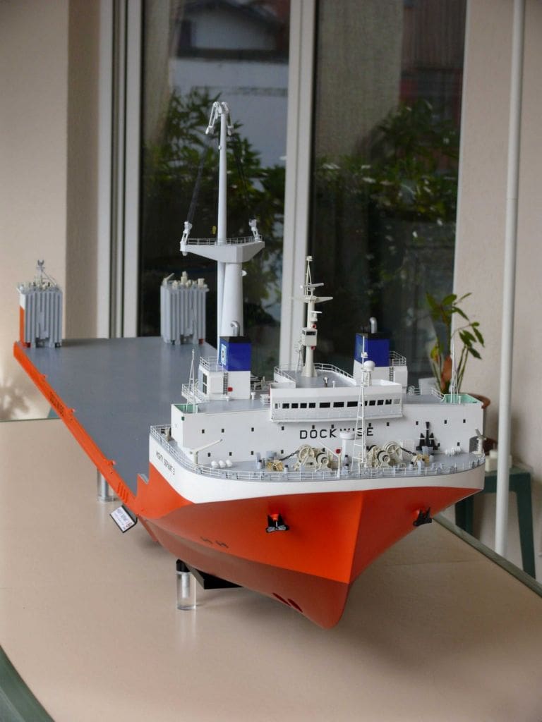
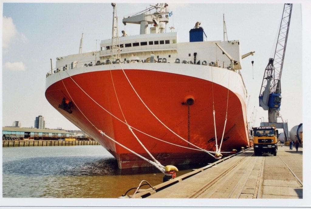
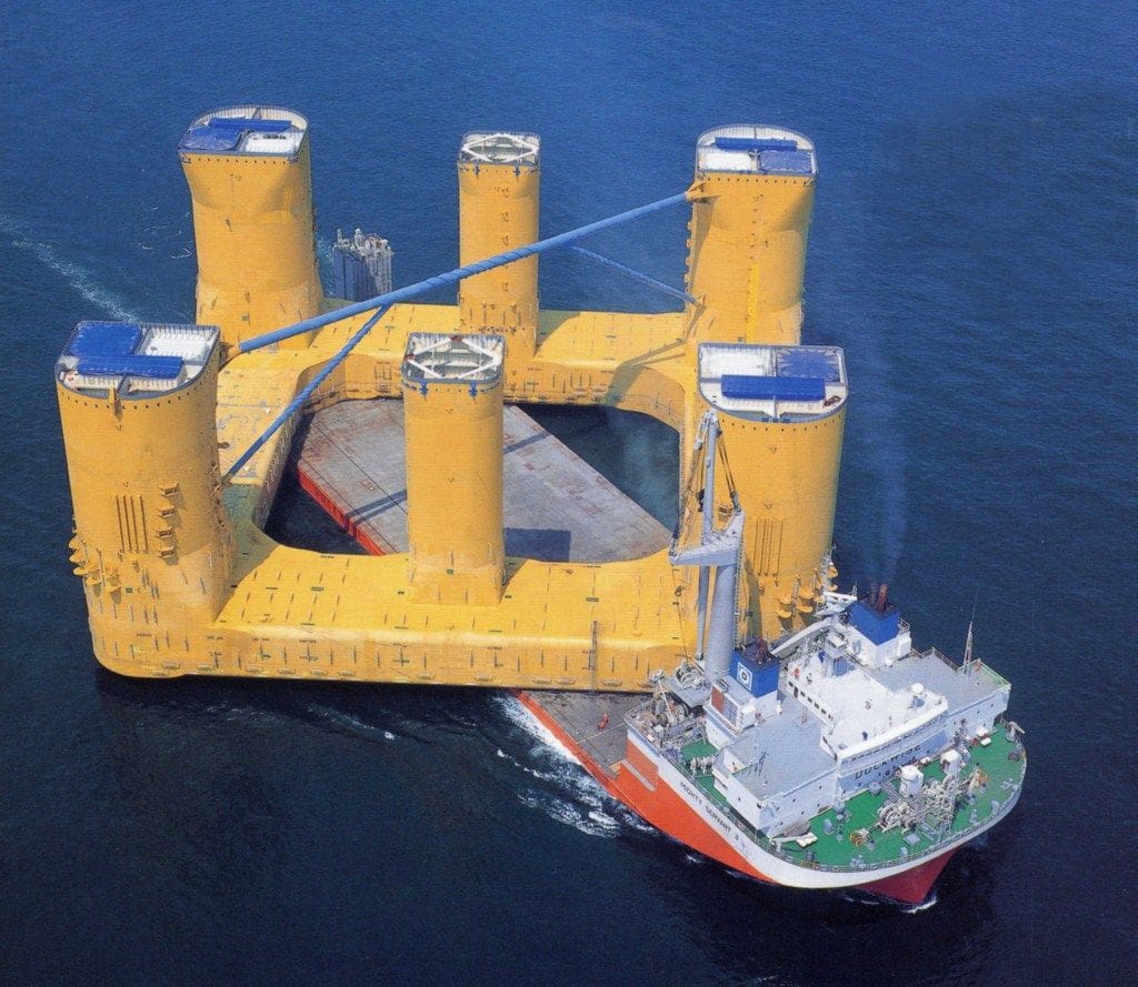
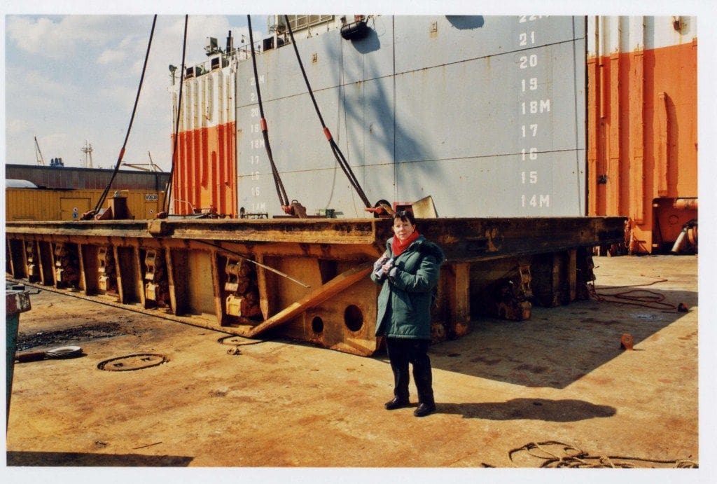
Her name is indicative of her function. ‘Mighty’ means she is impressive and ‘Servant’ means to serve! Her role is as a heavy transport vessel and she is actually a semi-submersible ship designed to transport objects or structures which cannot be transported in the usual maritime way. The bow looks like that of an aircraft carrier and there is a slim (in depth terms) underwater hull with a wide upper deck offering as much load carrying space as possible.
The forward superstructure and hull section includes the engines and generators etc., and occupies less than 20% of the total 181 metre length of the vessel.
Enjoy more Model Boats Magazine reading.
Click here to subscribe & save.
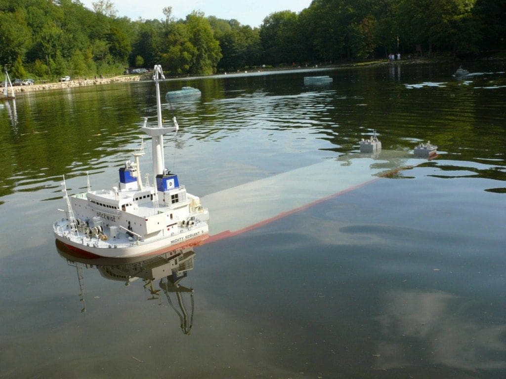
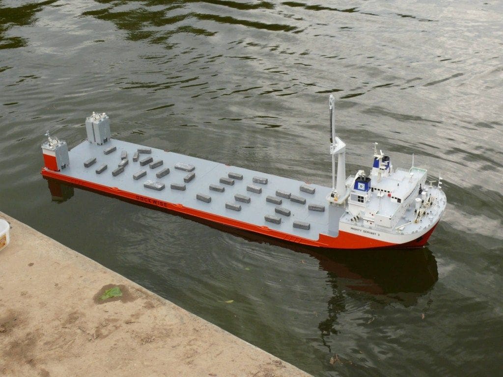
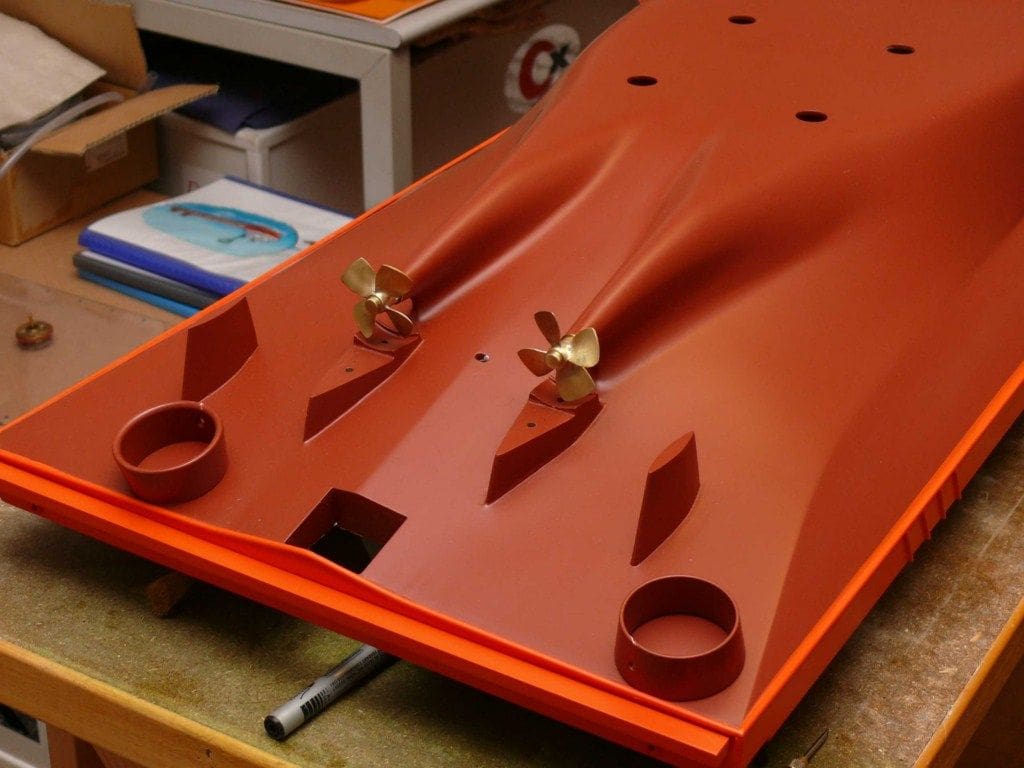
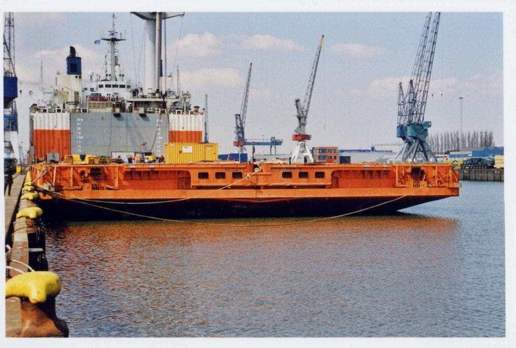
The rear of this superstructure is a vertical 12 metre wall dropping down to the loading deck. This is 140 metres long, 40 metres wide amd as flat as a football pitch. At the stern, two buoyancy casings help to stabilise the vessel when she immerses.
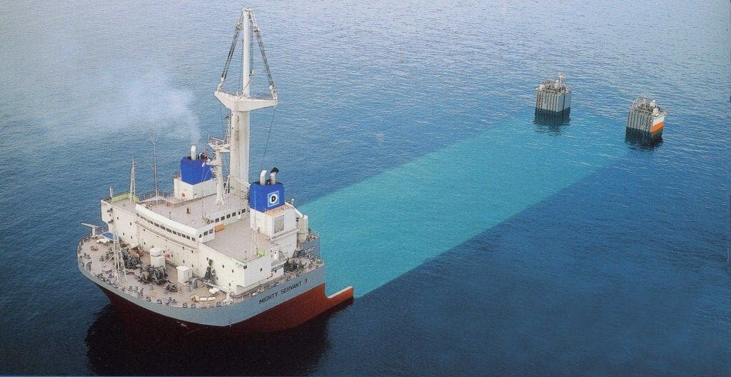
It takes eight hours for the deck which is normally just three metres above the sea’s surface, to change to 10 metres below and the converse absorbs a similar time span.
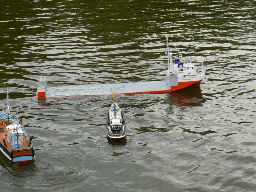
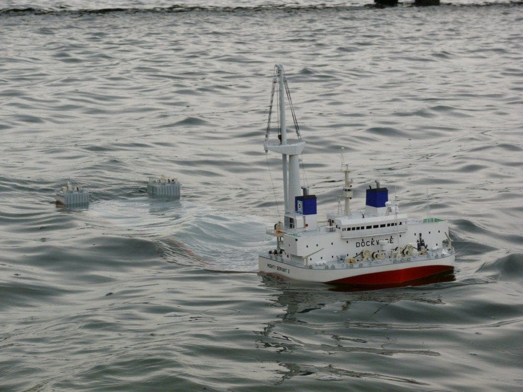
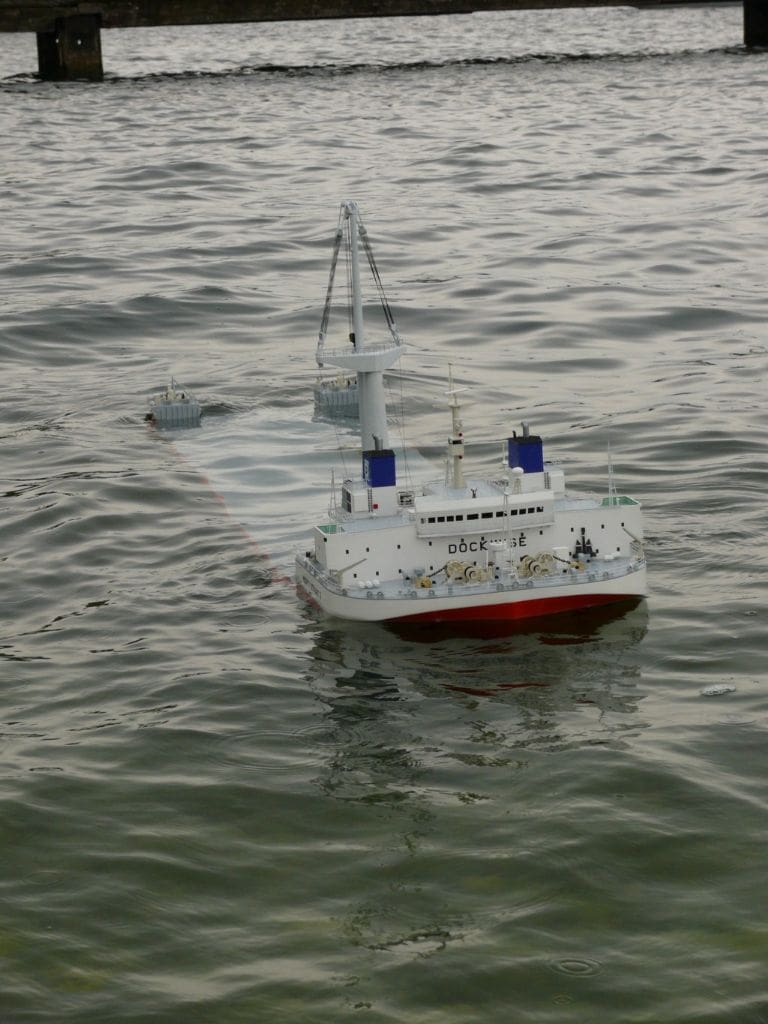
Thus a structure (another ship, oil rig, bridge parts etc.) positioned above the temporarily submerged deck can be slowly lifted clear of the water. The load capacity of Mighty Servant 3 is over 25000 tons. The position of the load has to be set to a variance of no more than a centimetre, the filling and the emptying of the ballast tanks following a precise programmed sequence in accordance with the load.
The stern buoyancy casings stabilise the vessel when she is ballasted down. Since they may get in the way of the cargo, one or both of them, can be easily unbolted and removed. Since Mighty Servant 3 cannot function without them, removable rails are fitted to the deck and these casings then self-winched to a convenient vacant space on deck.
Mighty Servant 3 also has another unique design feature. At the stern, she has a ballast-bar which is as wide as the vessel. This counterweight is approximately 230 tons and is the cause of the shape of the stern. At sea, it is firmly fixed to the hull, but it comes into use when the vessel is ‘sinking’ (usually in shallow waters). The counterweight is lowered (and raised) by two winches to and from the sea bed. This enables the safe immersion of the stern as the ballast tanks are filled or emptied.
There is also a 250 ton capacity crane at the rear of the forecastle which can manoeuvre objects on the deck and it can also remove or replace the four close fitting (and sealable) covers giving access to a conventional hold which is 100 x 16 x 7.5 metres in size. This can be used to carry cargo in much the same way as a normal vessel, but it can also be flooded when Mighty Servant 3 is transporting deck cargo.
Principle characteristics of Mighty Servant 3
181 metres long
40 metres beam
9 metres draft in normal conditions
15000kw total power
Two variable pitch propellers mounted inside nozzles
Two 500kw bow thrusters
Why such a vessel?
An oil rig or a ship being towed may only have a speed of four or five knots, but Mighty Servant 3 can easily achieve 14 knots. I first read about these vessels in 1988 in the French journal ‘Le Chasse Marée’. The Mighty Servant series were built in the mid-1980’s to meet a demand for such load-carrying vessels.
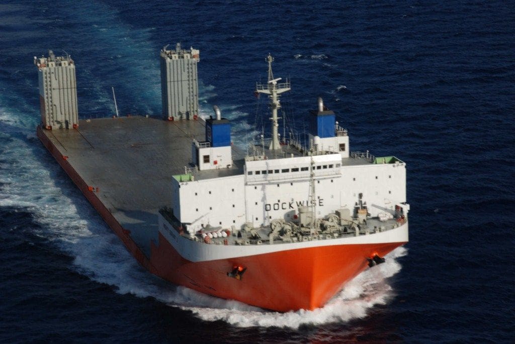
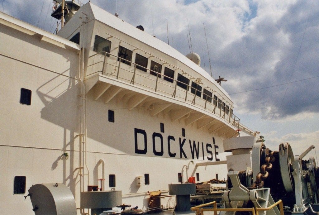
The shipowner was Wijsmuller, but is now known as Dockwise following the merger of Dock Express Shipping and Wijsmuller.
Mighty Servant 1 was the first and smallest vessel, followed by Mighty Servant 2 which was bit bigger and lastly by Mighty Servant 3, the biggest and longest. The three vessels looked very much alike, the major difference being in the length of the parallel body loading part. However, the vessels have all met different fates.
In 1999, Mighty Servant 1 was stretched and thus became the longest of the three, but in early November 1999, Mighty Servant 2 capsized off Singapore and was lost.
Mighty Servant 3 continued to serve normally until December 2006. Then whilst immersing (sinking!) off the coast of Angola whilst unloading a drilling platform, she continued to sink, and then totally! She lay down on the sea bed more than 60 metres down with just the crane jib poking above the surface. She lay this way for six months, before being raised in May 2007. At the end of January 2008, Mighty Servant 3 finally arrived at Grand Bahamas Shipyard, where she was repaired and renovated.
In 2009, Dockwise recommenced service with this vessel. Her silhouette had however been changed although the hull was still the same size. Visible modifications were:
The 250 tons crane was removed.
The front superstructure was raised.
The aft buoyancy casings were built higher.
The 5 ton crane was changed.
Dockwise currently is a shipowner with a fleet of about 20 semi-submersible vessels and is planning one with a 100000 ton capacity!
Their website: www.dockwise.com will give you more information.
Plans?
I have been able to build my model thanks to Dockwise, who provided me with a few basic plans of their vessel which were essential as a basis for preparing the model plans. They also allowed me to visit Mighty Servant 1 and Mighty Servant 3, but this was however pre-digital age (at least for me), so I took relatively few pictures.
The plans that were prepared matched the vessel as she was in 2003, that is to say they include the crane. The model ended up being 1.8 metres long and 0.4 metres wide. The drawn plans covered five square metres, so a lot of wall space was required for them.
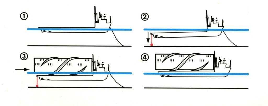
How to immerse?
The model had to immerse just like the full size version, otherwise the project was pointless. Similar to a model submarine (my other hobby if you hadn’t already guessed it), water would have to fill the ballast tanks, but not so much that the model would totally sink to the pond bottom. Indeed, it would still have parts of its superstructure above water, rather like a submarine running with its hull submerged and its conning tower exposed. A semi-submersible is in fact not half a ship or half a submarine, she is a unique vessel with specific engineering problems to be overcome. I suppose the nearest equivalent is a floating dock, and a look at the history of these, including British Admiralty ones, notes a number of disasters with a dock structures collapsing, bending in the middle or simply sinking when they shouldn’t.
Mighty Servant 3 immerses only whilst stationary and with her aft section lowering first. She must then stabilise at a very shallow depth, but as deep as possible, yet that depth is limited by the vertical space between the load carrying deck and the surface. She must be perfectly stable when commencing the lift, hence the rear casings. Thus the difficulty, is that on the surface she is stable and when submerged she can also be stable, but the problem occurs when changing from one to the other.
Water ballast is of course needed, whether a model or full-size, but the volume required is much greater than that inside a scale submarine and the model should at the very least be able to lift some sort of load, otherwise what’s the point? The model should also remain as horizontal as possible even if the load is not perfectly centred on the deck, which meant that a number of controllable ballast tanks would be needed, both port and starboard and forward and aft to enable proper balancing. So, this meant that a minimum of four (and actually six in the end) such tanks would be required for any degree of functioning realism.
Filling and emptying the ballast tanks?
The solution was is to let the water enter, not by opening a tap in the hull bottom but by opening an air valve at the top allowing air to escape as water enters via the permanent openings in the hull bottom. Pressurised air would therefore be used to empty the tanks.
Basic physics indicated that the air pressure required was not going to be particularly high. A pressure of around 20cms or about 8 inches of water height was all that was going to be needed. Expressed in bars (Kilogram per square centimetre), this represented only 0.02 bar or 0.3psi, so a small centrifugal compressor would be adequate for the task. The variety that can be found on a small battery driven vacuum cleaner could thus be readily adapted to the new role.
Speed of immersion
The immersion of a semi-submersible vessel is rather slow, but for a model? If the time scale was to be truly respected, then the model would need to immerse ten times faster than the original (square root of the scale of 1:100) which would require roughly 45 minutes, but in practice it should be only a few minutes otherwise boredom would soon set in! Therefore, the water had to enter or exit quickly enough for the model to be clearly seen to be changing mode.
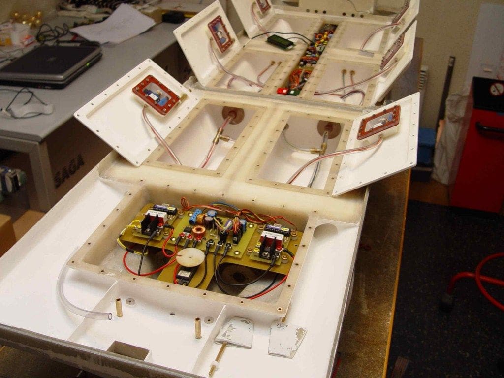
Also, the model structure must be quite light so as to be easily transportable, but stout enough to withstand the volume and weight of water when afloat (or barely afloat!) So quite a conundrum all things considered. The volume and therefore the weight of water ballast is considerable, much of which would be within the model, even when floating normally. Also, when submerged, the loading deck is actually free of the load waiting to be lifted. In the end, the model was designed with six self flooding ballast tanks and three watertight compartments for the motors, r/c equipment and the batteries etc.
Stability is enabled by the aft stern casings and non-visible lateral floats under the front deck. The role of the latter is similar to that of the aft casings, namely to retain stability as the model sinks or swims!
Everything considered, I realised that this model would not perform identically to the original, but would at least go up and down in some semblance of good order, or at least that was the plan! Don’t forget that to a scale of 1:100, in theory the model should be able to lift 25kgs clear of the water which would be no mean feat.
Design considerations
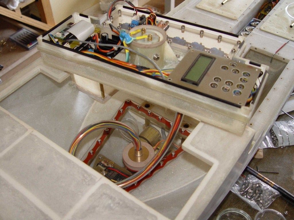
Ideally, the whole sinking and surfacing process on the model would be automatic, once the r/c signal to sink (or float) had been given and this is where I made the first technical choices and my first mistakes and an initial compromise turned out to be unsatisfactory.
On the real ship, most of the equipment is in the forward part of the hull. I attempted to put ALL the control functions in a box located under the forward superstructure. In this box were placed the receiver: a handmade small d.c. compressor and the servos operating the air valves for each of the six water ballast tanks. The batteries were to be at the bottom of the hull and the motors in a watertight compartment located in the rear part of the hull. At this stage, the ballast tank air valves were all connected to the air compressor via a common distribution manifold.
To sink, the plan was that the valves would open and the air escape freely via the compressor which at that time would not be working and be just an open airway. Thus, hopefully water would enters the ballast tanks and one or several of the valves could be closed while others were left open to ensure the model remained balanced and stable.
To rise, the compressor when operating would put positive pressure into the common distribution tank and if an air valve to a ballast tank was opened, water would be forced out of that tank. If the valve was then closed, even though that ballast tank was still open to the water, no more would enter because the air could not be displaced. At least, that was the theory!
First trials
Jumping ahead a bit to an uncompleted model, the initial trials were a partial success, but I was apprehensive about the model’s inherent instability during the immersion phase, and I was right!
On the surface, the model was stable and it was also stable when immersed, but the step between was very delicate to perform. It would I reasoned be fairly easy to revise the software programme for the six air valves, but the module containing all the electronics etc., weighed 1.4kgs and was on the top deck and still without the ‘proper’ superstructure fitted. This module was linked to sensors by an umbilical vinyl electrical cable and six pipes to the air valves. It was clear that this was all too complicated. So, I decided to start again as regards the internal layout, r/c gear etc. Anyway, back into a proper sequence now as I briefly describe the hull.
The hull
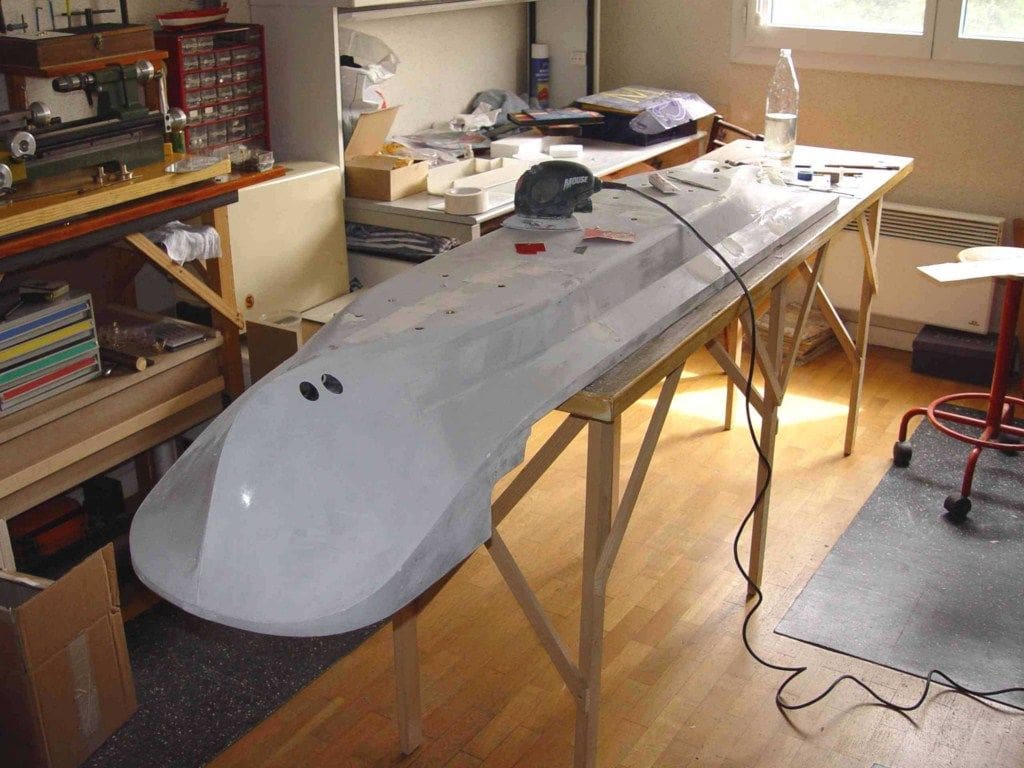
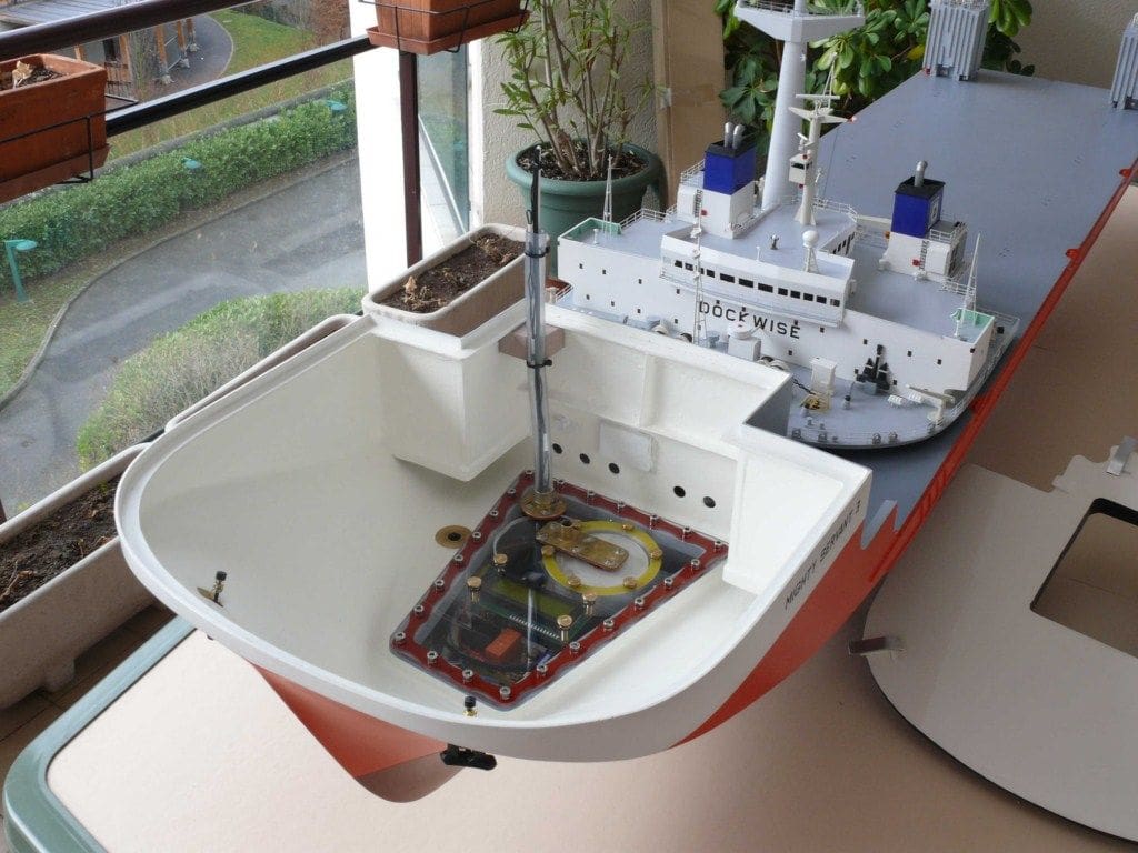
This was in two halves. Why? Well, yes it is only 1.8 metres long in total, but it is very cumbersome and awkward being 0.4 metre wide. So, being in two halves meant that it would be easier to transport and manage.
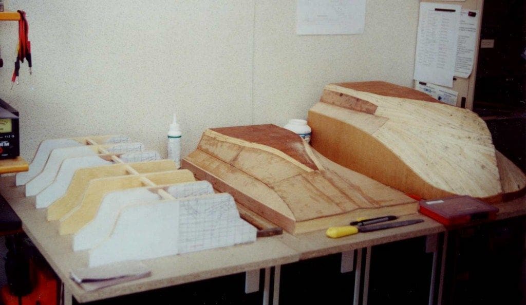
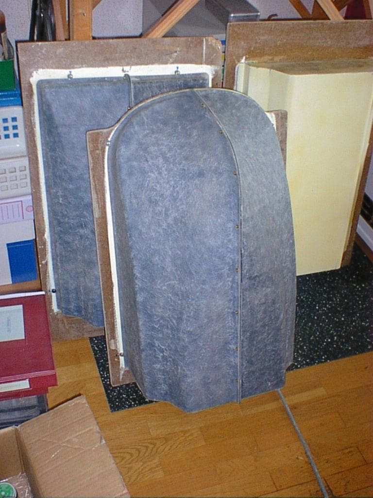
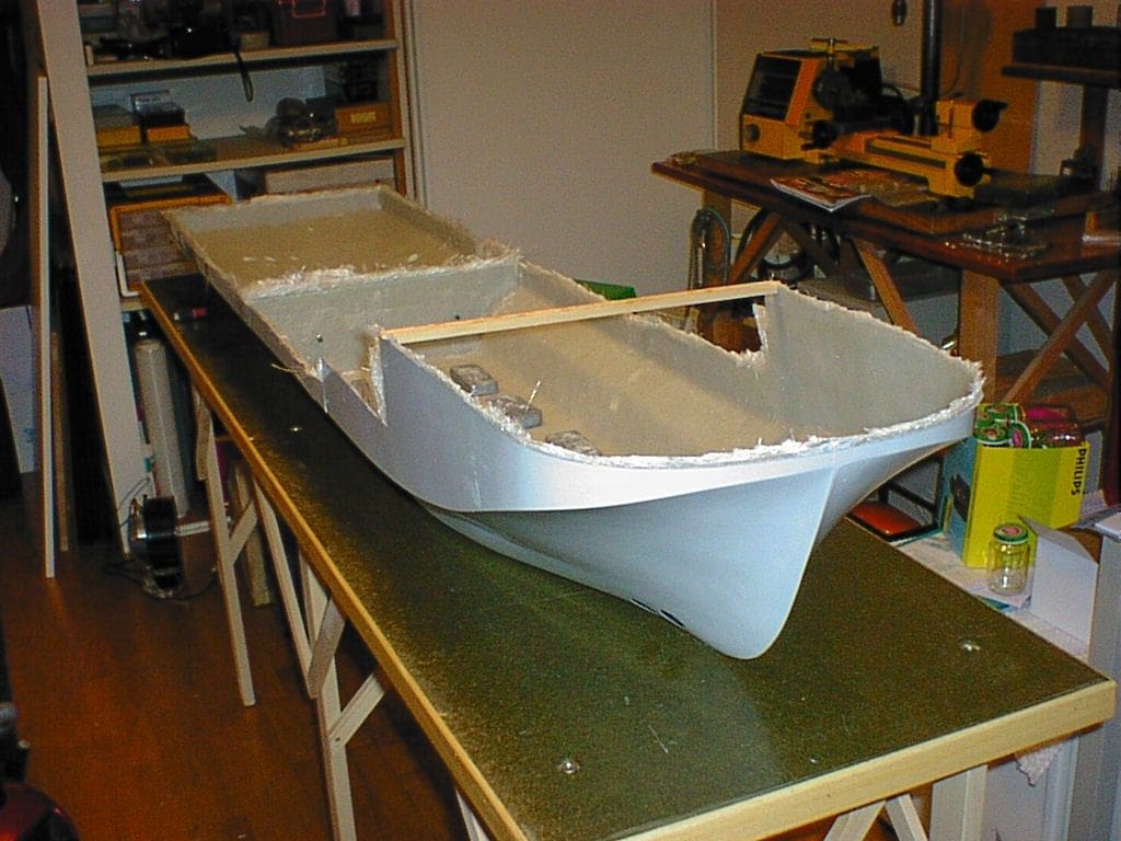
The hull is of GRP, laid-up in moulds prepared from masters of the forward section; the parallel central part and the stern section and its two propshaft fairings.
Using GRP takes time, but it’s worth the effort as the actual hull parts are then strong and unencumbered by internal ribbing. It is of course also possible to make more hulls from the original mould if required. A slight drawback was that the three GRP sections had to match up to each other perfectly and two permanently joined to each other, so some fettling on the GRP mouldings was inevitably required. I prefer standard polyester resin, even though it has an odour that some find is distinctly unpleasant. An alternative is a specialist epoxy resin, but that it is more expensive and will usually cure more slowly unless in a vacuum tent or similar.
The bottom of the hull was ‘laid up’ quite thick (about 2.5mm), with the sides thinning a bit for the upper hull parts.
Bow thruster
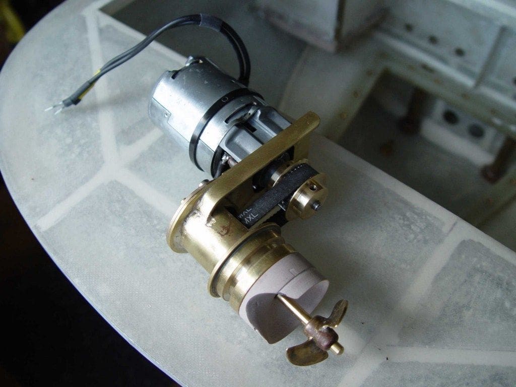
On the original there are two, but I compromised by just having one. The water actually flows in an ‘S’ shaped circuit. The first opening is at the front of the port side, entering a tube on the longitudinal axis of the model and exiting on the starboard side further back. The motor and impeller are therefore parallel to the longitudinal axis of the model.
The internal diameter of the main tube is bigger than the entrance and exit openings, thus it is more efficient than having the same diameter tube throughout. Dummy bow thruster openings on the direct opposite sides of the hull to the ‘real’ openings complete the illusion of there being two separate bow thruster drives.
Ballast tanks
The deck on which the water ballast valves etc. are set is located slightly below the load carrying deck, but above the normal operating waterline. In the forward part of the hull just inside the bows, there is a totally watertight compartment whose upper part is also just above the waterline. Behind this compartment, there is another narrow lengthways watertight compartment up to a bulkhead and between two side ballast tanks. Behind this are two more main ballast tanks.
In the rear hull section, there is a watertight compartment for the motors and rudder servo etc. at the stern plus two large ballast tanks forward of this. Any other open sections of the model are free flooding.
To allow and assist water entering and exiting freely, there are numerous pipes between the bottom of the boat and the upper sections of the hull. A total of six in the forward part and four in the stern section. The exterior openings are all in the hull bottom and thus cannot be normally seen.
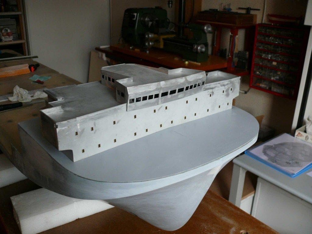
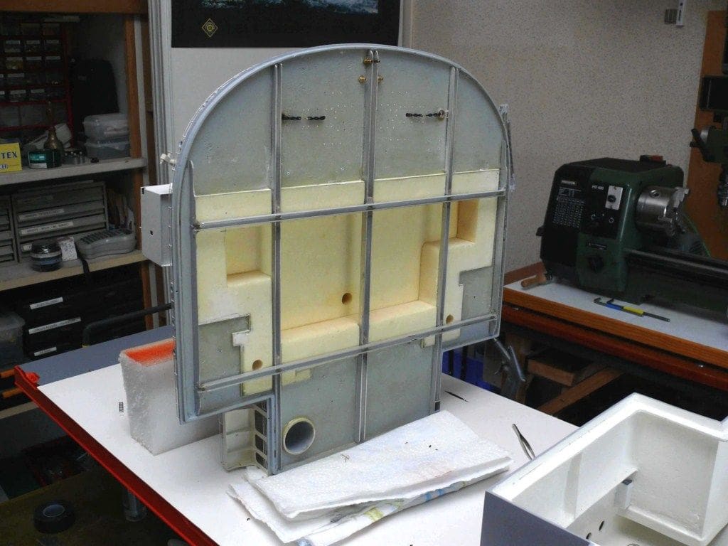
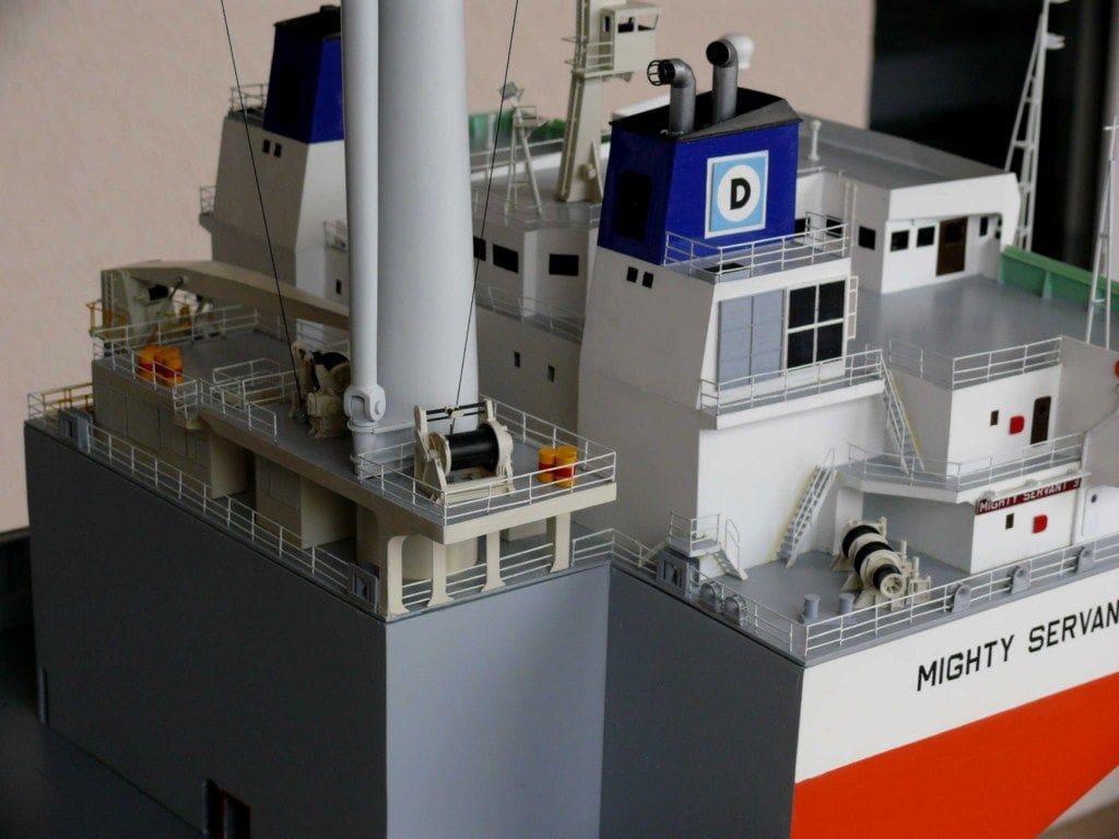
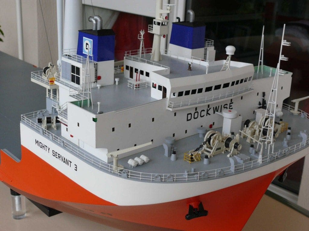
Main Superstructure
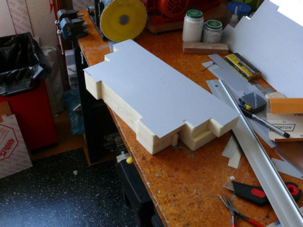
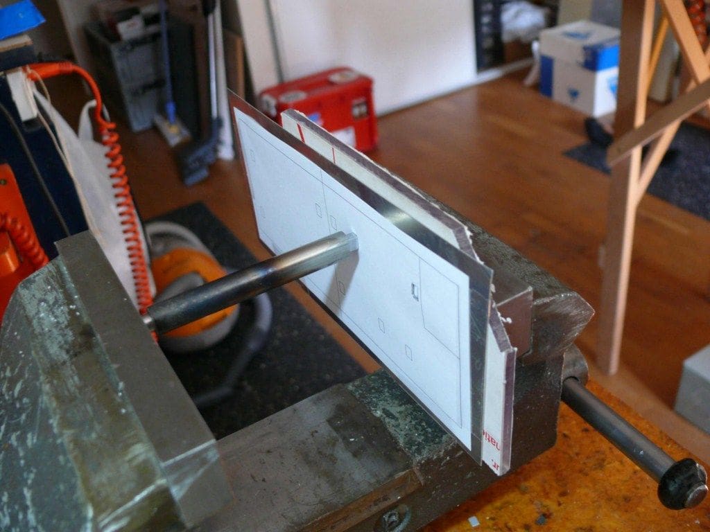
This is all on the forward part of the hull. As it had to be as light as possible, I thought I would make it of litho plate (which is very similar to aluminium) and is used in the offset printing business. One of my friends at the club was such a printer and had numerous redundant sheets suitable for my purposes. Trouble was, that it had to be glued as soldering was out of the question. You can create superb shapes with litho plate by scoring and folding it, but it is still quite fragile and is very prone to denting.
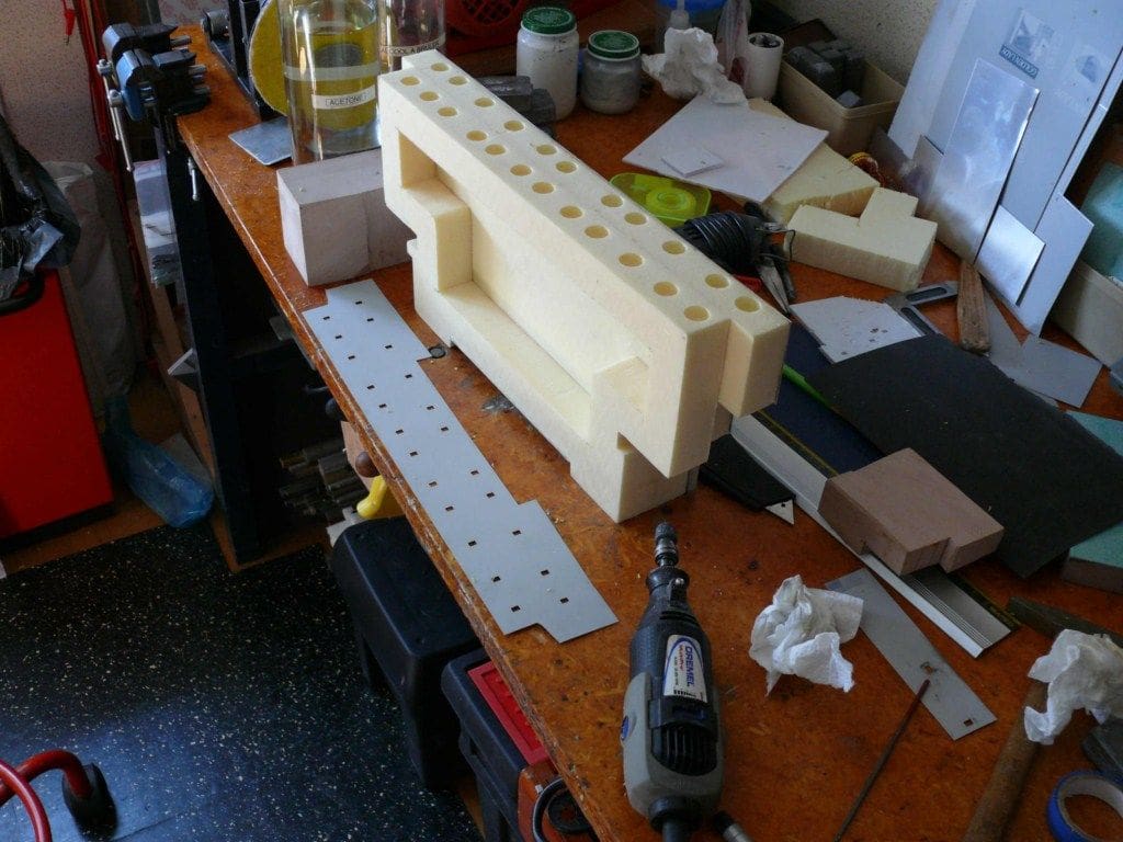
So, the whole superstructure was built around a hard polyurethane foam core, of the type used to insulate houses. Slow setting epoxy was the adhesive of choice and it worked well, the result being a very light, hard and smooth skin over a foam core, which meant it would also float.
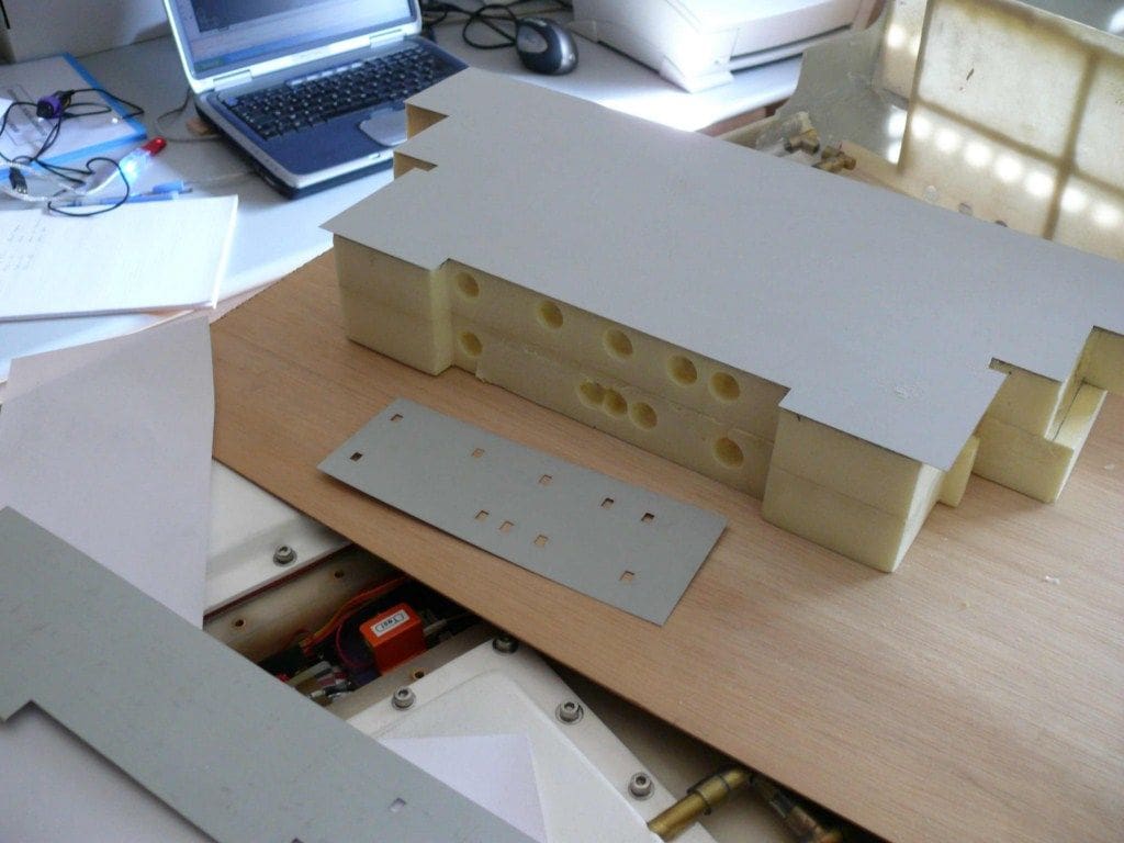
At each point corresponding to a window or porthole, a small indent was machined into the foam to give some depth to the opening.
Making the window openings in the litho plate wasn’t easy, but an especially prepared punch pushed into the litho plate (which was supported by a polycarbonate backing piece) did the trick.
To achieve neat and properly aligned cut-outs, a template was generated on a computer, printed and temporarily held by Sellotape over the litho plate. There is no doubt that using dense polyurethane foam as the backing for the superstructure outer skins and decks, worked well.
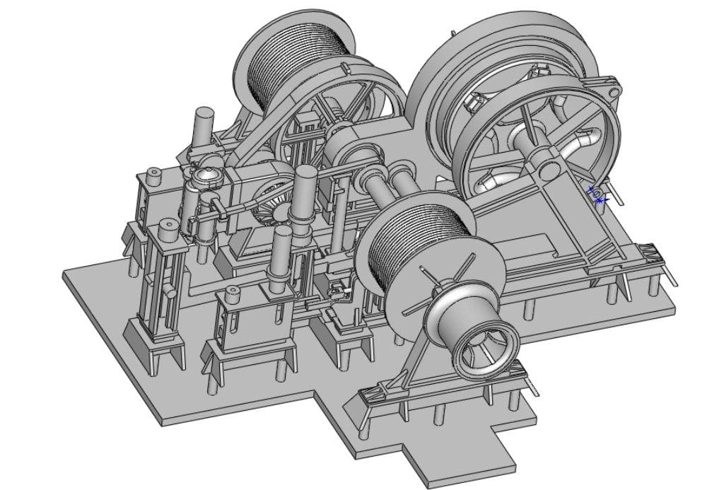
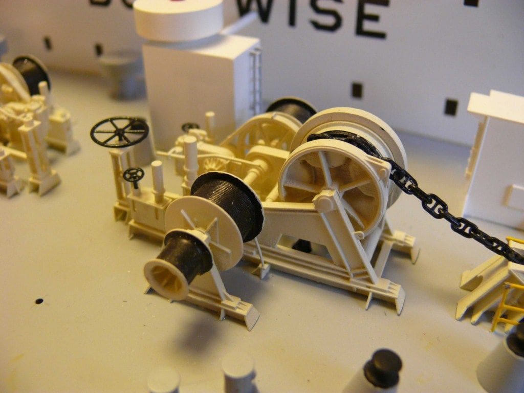
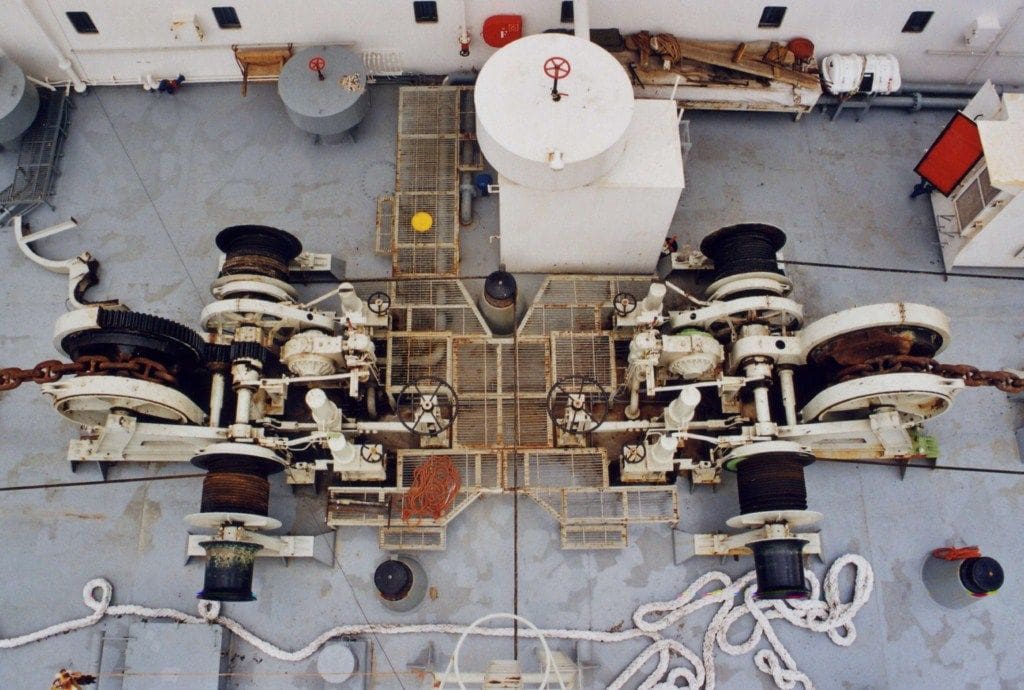
Winches
There are nine, some of which are identical to one another. For these I used an industrial technique usually known as 3D Printing or Fast Prototyping. 3D Printing is a form of additive manufacturing technology where a three dimensional object is created by laying down successive layers of material. There are several different programmes to create models directly from a computer file and some can even create a part in several colours.
For me, the machines which produced the fittings for this model used a transparent or blue coloured resin which permitted detail work of up to a 0.02mm accuracy. The machines are used in industry to create prototypes and are also used in dental practice to produce tooth moulds from a 3D scan of a tooth, but of course there are some drawbacks……
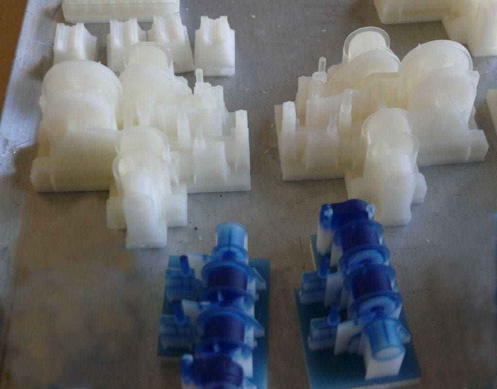
The manufacturing technique is very expensive and items are priced according to their volume in cubic millimetres. Roughly speaking, the machine will make something 6mm high in about an hour, so 30mm will require five hours. You will need to locate a business with such machines and fortunately for me I have a friend with this capability. The most important thing is that the 3D files have to be created first and that is the big headache. That is what took the time, many evenings and weekends to be truthful, with a simple winch becoming quite an intellectual nightmare to recreate in a 3D programme for the machine to understand.
The manufacturing process uses resin and wax, this second product being used as support when a complex item is created. The ‘unwaxing’ of the machined item is a difficult task and the best method was to dip the pieces into heated thinners, whilst controlling the temperature at around 50 degrees C.
On the pictures, you can see that the pieces when unwaxed have two colours. This shows particularly when the resin is blue. The blue/whitish parts were the surfaces in contact with the wax; those which remained translucent were not covered with wax. I have to admit this is not a process readily available to most model makers and I was fortunate in knowing ‘someone in the trade’ as they say.

Watertight?
Sections of the model have to be perfectly watertight, so the removable panels and the seals though the bulkheads for cabling etc., all have to be just right. For example, with a ballast tank cover, if there is a fault on the perimeter seal the tank may slowly fill thus altering the model’s depth in the water. In summary: ‘It is difficult for water to enter a watertight system, but once inside, it will never get out’!
So, great care was taken to ensure that the ballast tanks were indeed watertight and any cabling or piping entering them was also properly sealed at their entrance and exit points.
Motors
The two drive motors are located in the watertight compartment at the rear of the after part of the hull. They are secondhand 24v d.c. motors running at slightly above 3000rpm on 24v. Small, specially made, lipped rotary seals on the propshafts guarantee that the ‘engine room’ is indeed totally watertight.
The electronics for the stern part of the model, including the speed controllers, micro-controllers, rudder servo and the servo operated air valves for the after ballast tanks are all mounted above the motors in this compartment. The r/c instructions are actually sent via an optical link from the receiver in the bow section to the after section.
In the forward section, the bow compartment has a snorkel which rises above the water surface as the model sinks and it is concealed within the crane. Also inside this forward section is the bow thruster motor; its dedicated speed controller; magnetic ON/OFF switches and the air compressor.
There is a further compartment behind this bow section, containing the battery pack, receiver and the main electronic printed circuit board (PCB). At the rear of this compartment, there is a further small PCB interface for the forward air valve operating servos etc.
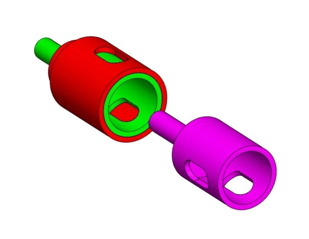
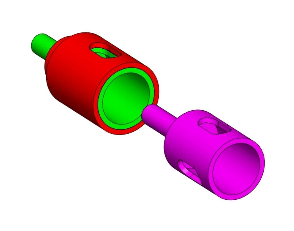
Joining the hull sections?
The plan was for two separate hulls which could be assembled and disassembled within a few seconds. Also, once locked together, no further electrical connections would need to be made.
Unusually, securing the two sections together is not done by hand, but by two geared motors within their own watertight compartments within the ballast tanks. They operate worm-driven threaded brass bolts that engage with matching threaded inserts in the other hull section. These bolts also carry the electrical supply to the other section, so these bolts serve a dual purpose.
However, this left the problem of transmitting r/c instructions between the two hull sections and as mentioned earlier, this is done optically.
On one side of a hull section is a powerful LED. On the other, a photo transistor and vice-versa, with a very small gap between both. In the forward hull section a coding circuit collects the information from the receiver and the main control PCB and sends them to the stern in the form of multiplex light pulses. This means that instructions are sent in very quick succession, one after the other. A micro-controller sorted all of this out! This is a programmable component, whose programme can be amended at will, thus allowing flexibility to amend the ballast tank filling and emptying parameters as desired. Nowadays, these types of component are very common and specialised electronic magazines are as a good a place as any to start learning about them. I used micro-controllers produced by the Korean Comfile Technology manufacturer.
Sinking?
The radio control instruction is issued from the Tx to the Rx in the model and then passed to the micro-controller on board the model which commences the flooding sequence, or the converse. This cycle can be cancelled at any time.
A two axis acceleration transducer measures the tilt and the pitch angles and thus the micro-controller reacts as need be by instructing the relevant servo to open or close its related air valve. An optical transducer can tell when the model is back to her normal waterline.
At the bottom of each ballast tank, optical transducers check whether they are empty or not and there are in fact several micro-controllers, each with different tasks.
The prime micro-controller is a Pic Basic 2H which manages the whole model, and others (Pic Basic 3B) are used as speed controllers, servo air valve controllers etc. Each of the drive motor speed controllers were designed by myself around a micro-controller with a conventional relay for changing from forward to reverse
Using computer software, it has been possible to programme the speed controllers to give superb slow speed performance. So in summary, don’t be afraid of electronics as they are easy to master if you have the inclination!
Air valves
Each is controlled by a servo, located inside the ballast tanks and underneath the covers. Small umbilical hoses, inside of which are the servo leads, connect them to the main control section, except over the break in the hull where the optical connections are made.
These valves have three distinct operating positions.
1) Closed: Air trapped in the ballast tanks prevents water from entering.
2) Open: Air escapes freely and water fills the tank(s) from the bottom.
3) Emptying: Air coming from the compressor forces water out of the ballast tanks.
The controlled sinking and surfacing are managed by the main PCB board which intelligently diagnoses the messages being relayed to it from the sensors. When ‘sinking’ and the forward section of deck starts going beneath the surface, this is when stability goes ‘critical’. The downwards ‘sinking’ stops when the floating foam block under the forward deck exerts pressure on the water. There are also two similar foam side ‘wings’ which help stabilise the model.
The compressor draws in air via the snorkel to create the positive pressure in the ballast tanks to expel the water. The r/c antenna wire and a small flexible pipe also pass through the snorkel. What is the pipe for? Well, because the batteries are all inside a sealed compartment, there is a possibility of gas being given off and accumulated in that sealed compartment when they are being charged.
Injecting some compressed air through this small pipe forces out any possible inflammable or explosive gases via the snorkel.
The air outlet of the compressor is split in a ‘Y’ such that one arm of the ‘Y’ feeds three port side ballast tank air valves and likewise for starboard. The air valves were carefully mounted to be normally just above the waterline. Thus, should a malfunction occur to any one of them such that it couldn’t close or open properly, water would not rise too high to permanently sink the model. Without this precaution of an inverted siphon arrangement, there would be a distinct possibility of an unintended and terminal sinking.
Transparent polycarbonate covers
These cover the ballast tanks and 2mm thick silicone seals ensure they are watertight, but care has to be taken when cutting the seals. The benefit of the covers being clear is that internal equipment in any compartment can be readily viewed, plus of course if water is where it shouldn’t be, then that is also obvious. However, they also create a problem that if rubbed to keep them clean, then static electricity can occur which might (and has from bitter experience) caused delicate electronic components to malfunction. This did occur previously with one of my submarines, which of course gives you yet another clue as to my interest in Mighty Servant 3.
The r/c system is 41MHz FM system (okay for use in France). Interference can be a problem, but it does work underwater, whereas 2.4GHz doesn’t because the higher the frequency, the more the water will stop the electromagnetic transmission. So, one is between the devil and deep blue sea. Another problem looming is that manufacturers are in many cases now producing only 2.4GHz sets which will mean a growing problem for submarine model makers in years to come.
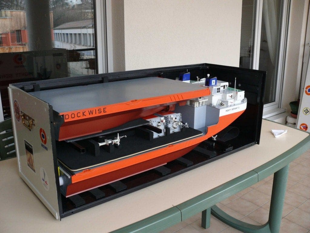
Transport and storage boxes
I make my transport and storage boxes using hollow steel profiles and plywood. Because Mighty Servant 3 is in two halves, the transport box is actually just 1.2m in length; 43cm high, and 46cm wide. The crane, masts and rear casings are also easily removed for convenience and are be stored in a special dedicated shaped foam tray.
Summary and conclusion
The model works and does what is intended in a controlled fashion. The six ballast tanks fill naturally and water can be expelled by compressed air which enables the model to lift a cargo, be it an oil rig, another model boat, or some other large object. The micro-controllers enable the flooding and expelling of water to be controlled such that the model does not capsize or dive to the pond bottom!
Should you choose to build a working Mighty Servant 3 or similar, then it will a challenge, but you will end up with a unique model that will stretch your model making skills into electronics, physics and all the other technical aspects of such a model. When operating the model, its unique capabilities will repay all that midnight head scratching and sleepless nights.
However, one thing is very certain: With its bright orange colour scheme you shouldn’t lose sight of it either on or below the water!
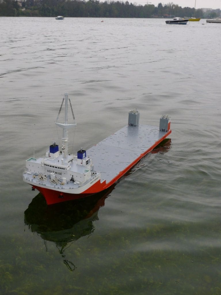
The photos below show the model in operation in various degrees of flooding down