CARL A. LLOYD presents a novel leak proof method for model boat drivelines
I have long had a fascination for model boats and in particular, tugboats. Perhaps this is due to my career as a mechanical engineer and my interest in all things mechanical, or my exposure to tugs on the Erie Canal in New York State which is very close to my home. In any case, tugs are an interesting mix of machine and art, and I am always on the lookout for tugs to photograph or paint when we are in harbour towns or ports.
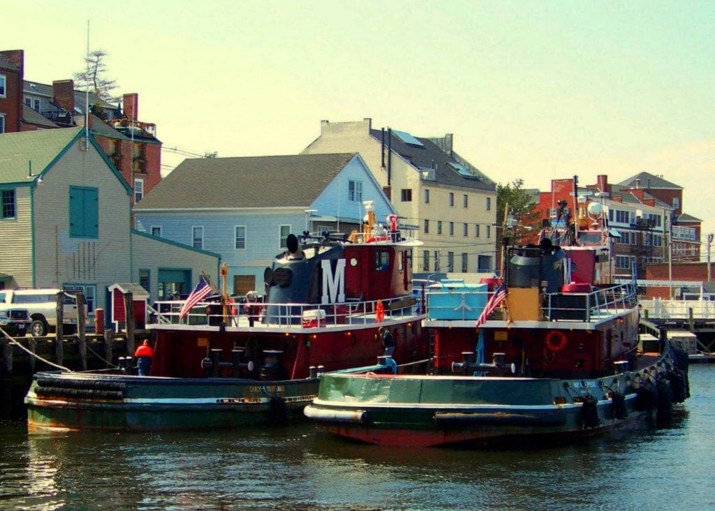
About two years ago, I purchased a model boat kit when on vacation in Portsmouth, New Hampshire, at a wonderful shop there called Tugboat Alley. The model is a styrene/wood kit by Dumas which replicates the tugboat Carol Moran. This is a diesel electric harbor tug, representative of those frequently seen in USA east coast ports such as Portsmouth. The model represents the real thing at a scale of 1:72 and is about 18 inches long with a beam of 5 inches. The kit includes components for an electric motor drive and working rudder to make it capable of radio control operation. Upon opening the box and reading the instructions, I became aware of the method used by this kit to seal the propeller shaft tube so that water does not enter the hull when operating. This is the typical ‘stuffing shaft’ approach in which the drive shaft passes through a relatively long and close fitting tube which is sealed to the hull and filled with grease to keep the water from entering through the clearance between the rotating shaft and the tube.
Enjoy more Model Boats Magazine reading in the monthly magazine.
Click here to subscribe & save.
My plan was to use this boat in our backyard pool and I did not look forward to leaving an oil slick in the pool whenever the model was used. In addition, although I knew the grease barrier would work fairly well, it might not be a perfect seal and some water would eventually find its way into the hull. Since the deck on this model is permanently bonded to the hull, access to the interior of the hull for water removal would be difficult. Finally, the method of repacking the shaft involved removing the drive shaft and pushing new grease into the tube at regular intervals and this process seemed inherently messy and bothersome to me. Therefore, I wanted an alternative approach to the stuffing tube.
Concept
I went through some mental gymnastics and several pads of sketch paper investigating the alternatives available to prevent water entry. The usual things came up: Elevating the motor above the waterline; using proven shaft seals such as O-rings; the traditional faucet seal using a compression gland, etc, etc. All of these solutions had worked for some applications but in my opinion had drawbacks for a model boat.
One solution became more intriguing to me as I considered the choices. This involved a device with which I was familiar from my experience designing test equipment for components which must be operated in a vacuum chamber. If rotation of a component in the vacuum chamber must be performed, either as a test of the part, or an adjustment of the position of a device, there is a coupling which can be used to transmit the desired rotation through a thin walled extension of the vacuum chamber by the use of coupled magnets. The advantage of this is that the motor, gearing, electronics, etc., which are required to produce the rotation, can be located and operated outside the vacuum chamber and the challenges of lubrication, heat dissipation, power supply, etc. are greatly simplified. This is very similar to the concept used by some aquarium pumps, in which the motor is mounted in a housing which is below the water level and drives a pump impeller by magnetic coupling of a set of magnets across an axial barrier. However, in the vacuum coupling arrangement, the magnets are oriented concentrically, as opposed to axially. This avoids the thrust load inherent in the axial arrangement and provides a better magnetic coupling torque.
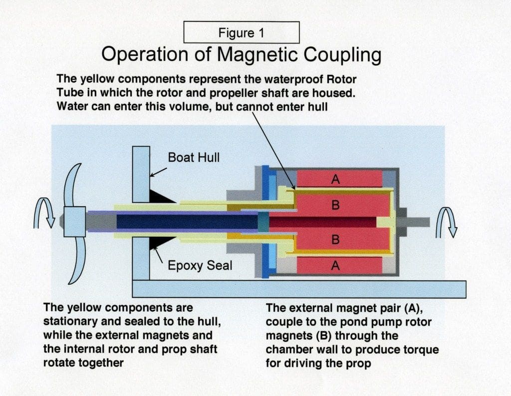
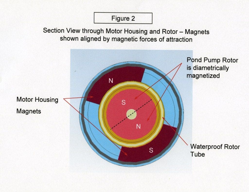
In this design, the driving magnets are supported by bearings on the outside of a thin tube of non-magnetic material and the driven magnets are supported by another bearing system on the inside of the thin tube and inside the vacuum (or water) environment. The thin tube maintains the seal while allowing magnetic coupling across the seal. There can be two or more sets of magnets depending on the size and torque required. The magnets are arranged so that there are alternating north and south poles on the outer set as well as on the internal set, or rotor. When the unit is assembled, the north poles of the external magnets line up with the south poles of the rotor, and vice versa, see Figure 1 for the general idea. Torque is developed when there is a load on the rotor and the stator is rotated. As the north and south alignment is displaced, the forces of magnetic attraction try to restore alignment and create useful torque, Figure 2.
This design seemed very promising to me for several reasons:
1) There is no leakage of water across the coupling.
2) There is less friction or drag than the greased stuffing tube approach.
3) Maintenance is infrequent or eliminated completely.
Further Investigation
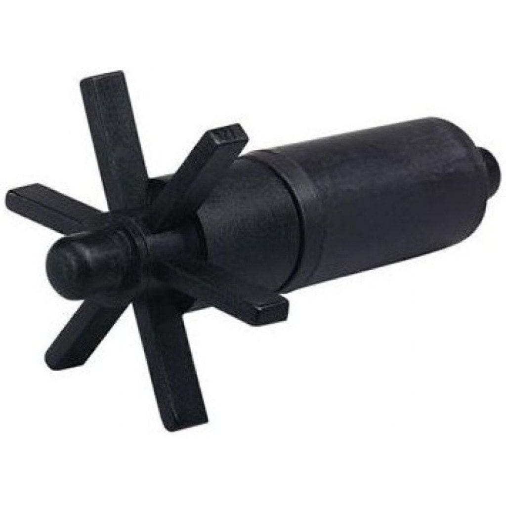
To investigate this solution further, I created a ‘proof of concept’ model. The major challenge here was what to use for the rotor. I needed a small diameter, cylindrical magnet that was diametrically magnetised. That is, the magnetic field varies from one side of the cylinder to the other, as opposed to axially magnetised, where the north and south poles are at opposite ends of the cylinder. I found several sources of suitable cylindrical magnets by searching on line, but finally settled on a pond pump rotor, available as a replacement part for a small pond pump, Figure 3. This was ideal because it came with features that could be used for support bearings and the magnets are epoxy coated for constant use in a water environment.
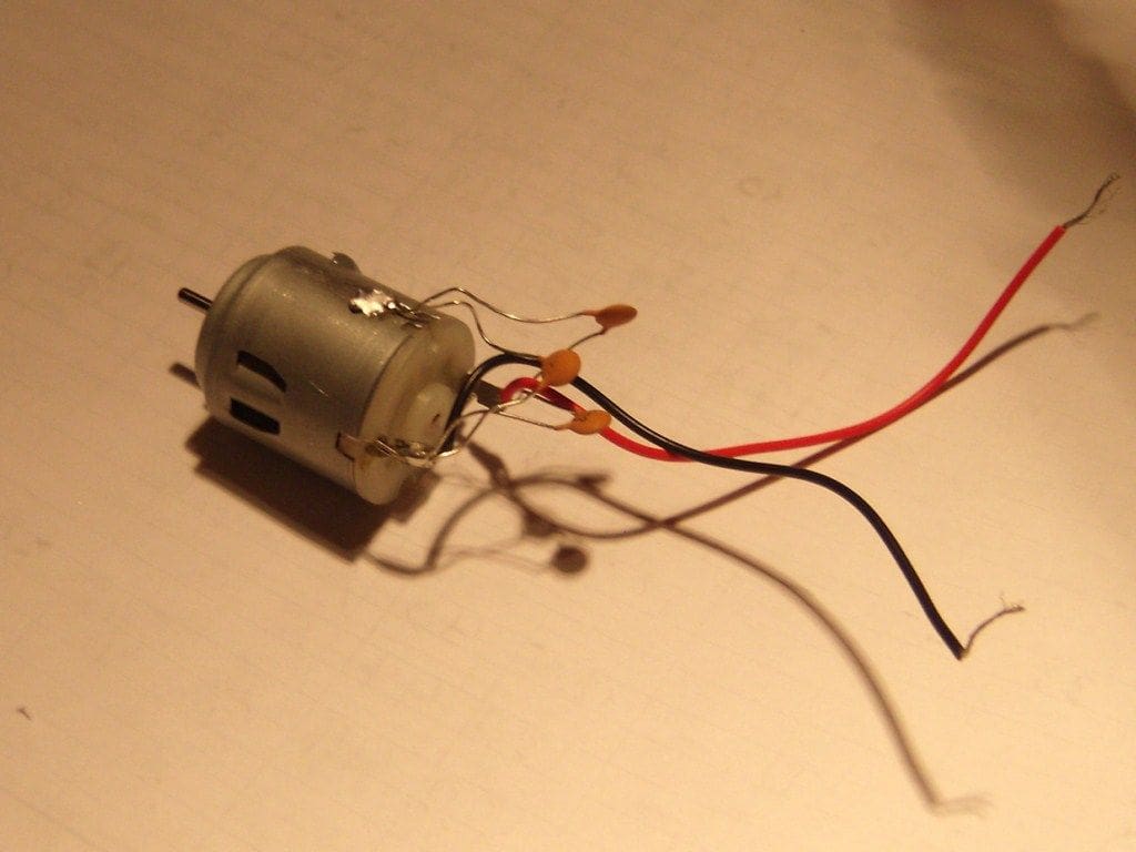
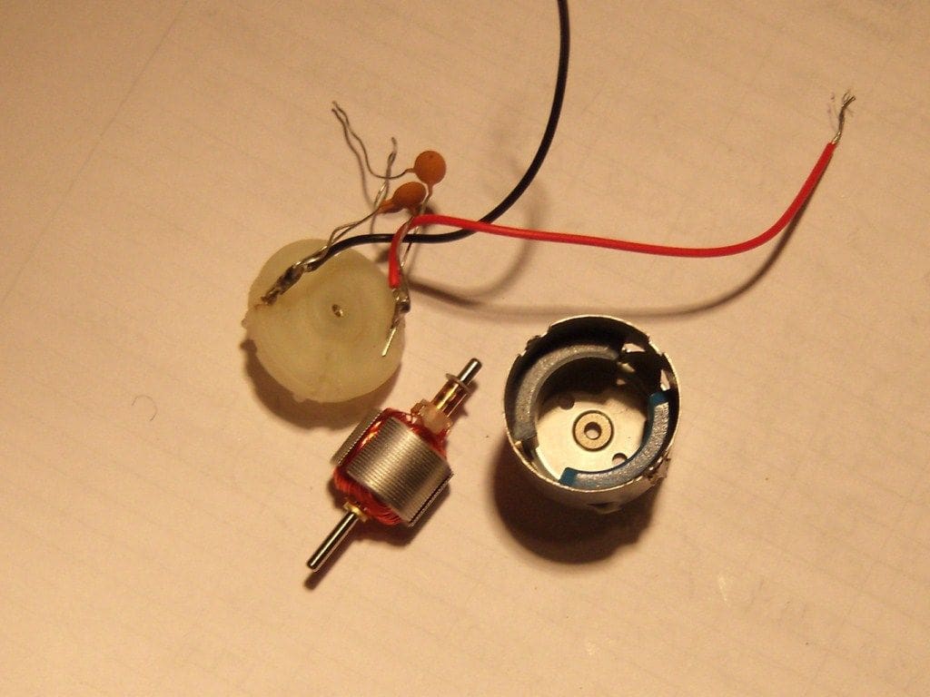
With a good representation of the rotor in hand, I looked for a way to provide the external magnets. Again, the on line search provided several choices, but the magnets would have to be housed in a tube of the proper diameter and supported on bearings to maintain the concentricity of the assembly. With my scrounging skills switched on, I found a permanent magnet, brushed DC motor, Figure 4, in my workshop which, when the armature was removed, had the two magnets I needed, mounted in a tube (the motor housing) with the magnet inside diameter that was just right, Figure 5. The air gap between the inside of the motor magnets and the outside of the pond pump rotor was about 0.075 inches, large enough to accommodate a thin sleeve and still maintain running clearance, yet small enough to realize a good magnetic coupling.
As a proof of concept, I decided to test the torque capacity of the assembly. After removing the pump impeller from the pond pump rotor, I positioned the rotor in the motor housing and used the motor end bearing and a steel pin to maintain the rotor in a centred position. The rotor had a slot in the exposed end (to key the impeller) that allowed me to use a screwdriver to apply torque to the rotor. While holding the motor housing stationary, I applied torque to the rotor using the screwdriver and was pleasantly surprised at how much torque was required to overcome the magnetic coupling alignment. I did not have a quantitative measurement at the time, but felt certain that the torque capacity was more than enough to drive the propeller for the tugboat.
Armed with confidence that the design was practical for my purpose, the next step was to build a working prototype complete with the necessary waterproof tube, bearings and features to allow mounting a propeller on the drive shaft and an electric motor on the input end of the stator housing.
The prototype
Since the next version was the prototype, I was interested in scrounging as many of the components as possible to minimise the cost of the coupling. Since I had a good match between the motor housing and the pond pump rotor, I kept these components and designed the rest of the assembly around them. I have a CAD system on my home computer that is excellent for designing things like this, so I began the process of laying out the 3D model of the coupling. Please see Figure 6 for a section view of the design.
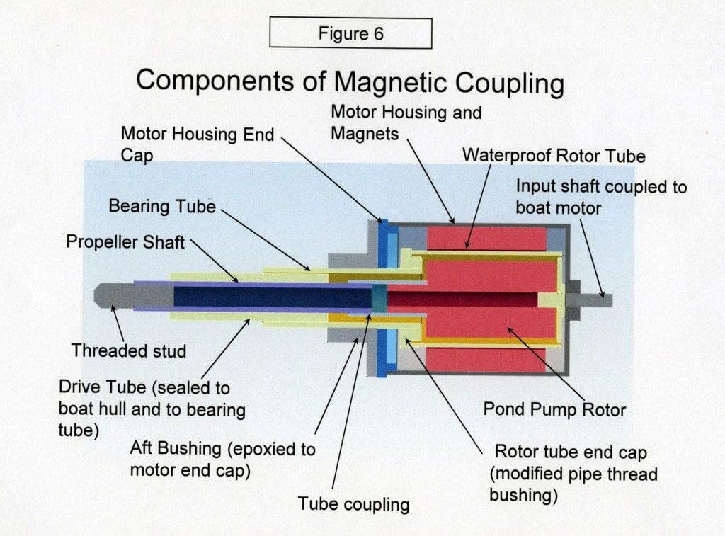
I took measurements of the motor housing and rotor using a digital Vernier Caliper that is accurate to about 0.001 inch. Next I added the thin walled rotor housing tube that would provide clearance on both the outside and the inside for the two magnets to rotate without interference. I found a standard size brass tube that came close to the ideal dimensions and established the length to enclose the rotor. The forward end of the rotor tube was closed off with a thin circular plate with the intent to epoxy this into the end of the tube. The output (aft) end was closed with a modified brass pipe thread bushing which stepped down the i.d. of the tube to a diameter that would allow me to thread the motor housing bearing tube in place. During assembly, I sealed this thread using epoxy to make it watertight. The aft bearing for the motor housing consists of a plastic flanged bearing that is epoxied to the face of the existing plastic motor end cap (after removing the brushes). After bonding the flanged bearing to the motor cap, the motor cap was drilled out to the same diameter (0.375 inches) as the bearing to allow the assembly to spin on the stainless steel bearing tube. Inside the stainless steel tube, a plastic tube is inserted and bonded in place. This plastic tube (originally a BIC ballpoint pen) is the bearing for the propshaft. In my case, it is about two inches long because the tugboat hull narrows towards its aft end and the magnetic coupling must be located far enough forward to allow it to rotate without rubbing the inside of the hull. The propshaft is another brass tube which fits very nicely in the BIC pen tube with very little free play to cause chatter when running. At the aft end of the propshaft, the tube is tapped to accept a 4mm x 0.7 metric machine screw. A stainless steel stud is threaded into this shaft and protrudes about 0.5 inches to provide an interface for the propeller. I used a locknut to secure the propeller on the shaft. The plastic BIC pen is the component which passes through the hull and is epoxied at the exit hole to make it watertight.
At the other end of the coupling, I used a steel pin, epoxied into the rotor tube end cap, to provide a second bearing. The rotor has a bore which turns on this pin, and the pin turns in the motor housing as well, ensuring that all components are maintained in concentric alignment.
I found a part from an old computer tape drive system that had a bore and set screw sized to accept a motor shaft, with a diameter suitable to epoxy to the front end of the motor housing of the magnetic coupling. With this in place, the coupling is complete and can be attached to the model propulsion motor.
During the process of designing and building the prototype, I went back and forth between design and assembly as I found parts that were close to what I needed. I then updated the CAD model to reflect what was available. For tube parts, I used the CAD system to tell me how long to make the parts and to confirm that I had the necessary clearances built into it. The thrust bearings for this system are inside the rotor tube, where thin plastic washers control the axial clearance in both forward and aft thrust conditions. I used a slow curing, flexible epoxy for this assembly for all of the bonded joints. The entire assembly was completed prior to bonding the propshaft tube into the hull. This allowed me the opportunity to test the operation and verify that the torque transmission was still adequate and that there were no binding issues before it went into the boat. For those who are interested, the detent torque (the torque required to cause the coupling to lose magnetic alignment and slip to the next aligned position) was measured at 3.0 in-oz.
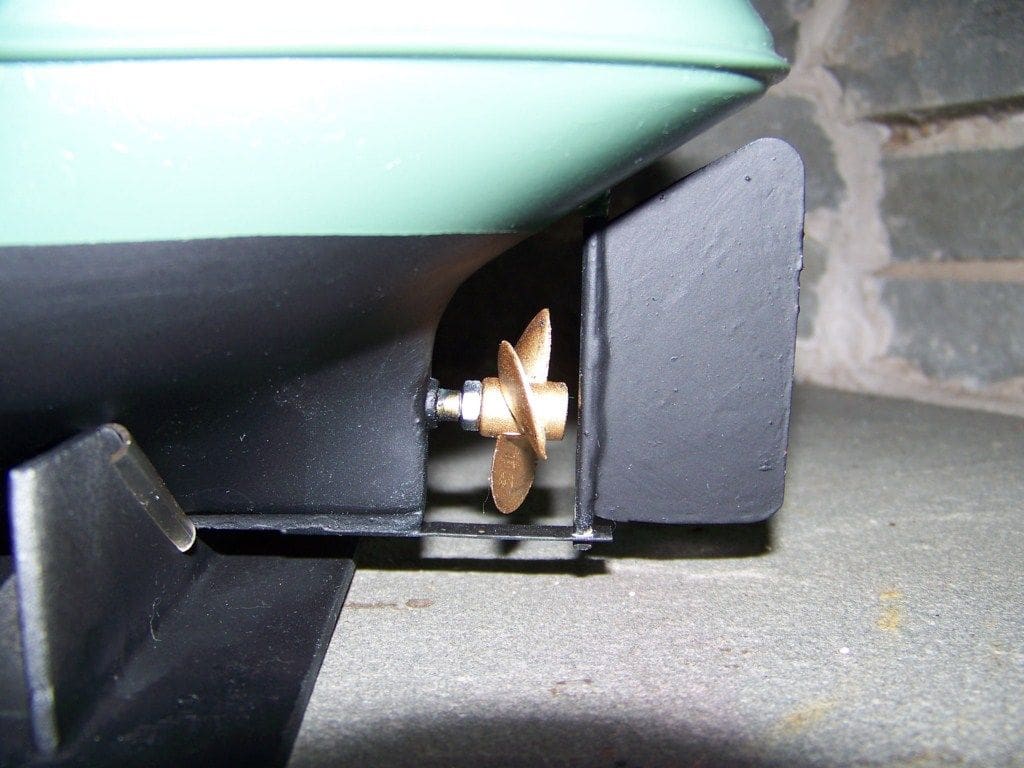
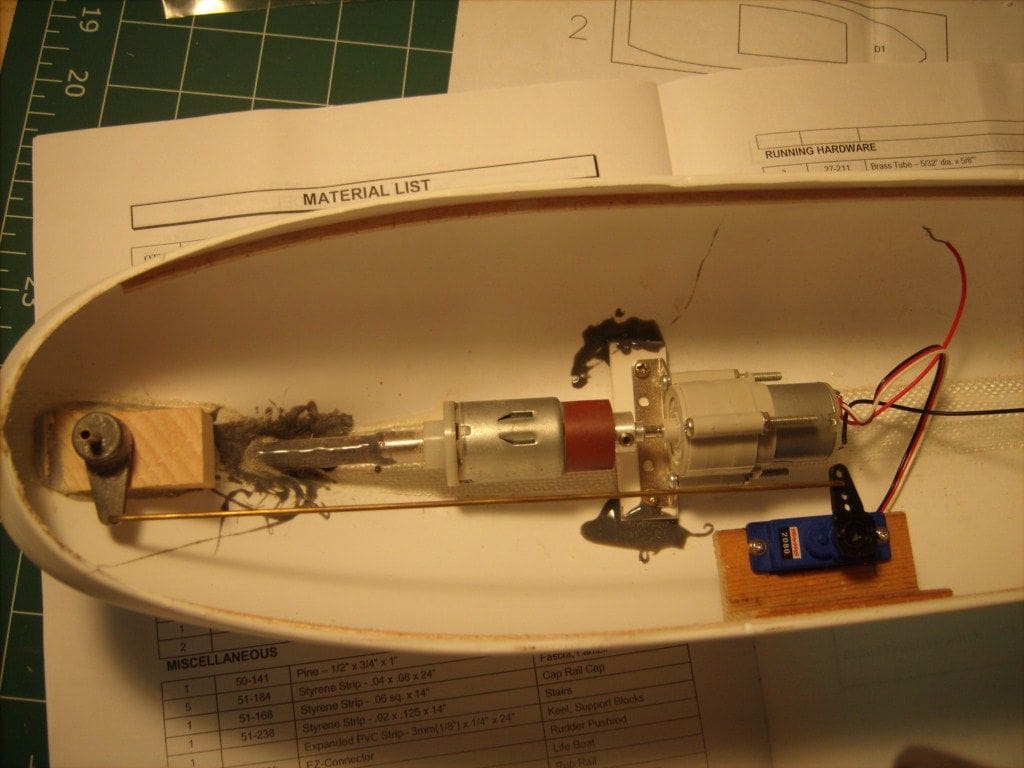
The propeller that came with the model kit was a small one inch diameter two blade plastic prop that seemed too small to represent what would actually be seen on the real tug. It probably would function very well on the model, but the appearance was an issue for me. I visited my local hobby shop and found a 1.38 inch dia. three blade propeller (Robbe model No. 1474) with a threaded insert for mounting on the 4 mm x 0.7 threaded shaft. This propeller looks like the real thing on the boat, Figure 7. However, I was concerned about driving this prop at direct motor speed and either having the boat run too fast or overheating the motor, or indeed perhaps both. A reduction gear seemed to be indicated and I found a nice unit at the hobby shop made by Tamiya (item No. 72001). This is a planetary gearbox which can be assembled with ratios from 4:1 up to 400:1 depending on which parts are used. I elected to go with a 5:1 ratio and introduced this unit between the motor and the magnetic coupling. Please see Figure 8 for components assembled in the hull. I used a 12 volt DC brush motor from an aftermarket automotive window washer pump as my drive motor. This motor mounts conveniently to the gearbox and its inbuilt fasteners are used to attach the assembly to a right angle bracket which is epoxied to the hull for support. The battery pack is a 7.2 volt unit. At full speed, this drives the motor at plenty of speed for tug operation and guarantees long life for the 12 volt motor. The reduction gears also make a very nice tug engine sound!
Testing?
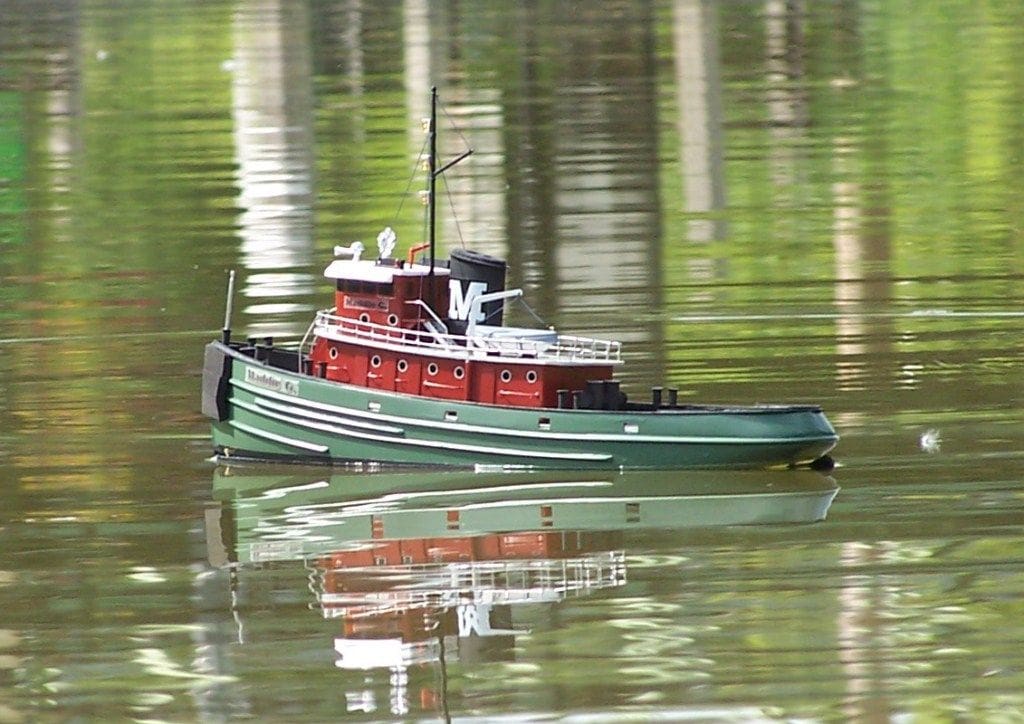
As of this date, the tug has been completely assembled and tested on the water with no leaks. In addition, the motor can be run at full power in the water without any coupling slippage, Photo 9. I am very satisfied with the prototype coupling and the knowledge that I will never have to take the drive apart to inject grease into the tube or clean up grease or water from the inside of the hull.
With this experience behind me, I am looking forward to another build and improving the magnetic coupling design to a next generation stage. There are a few things I would do differently on a subsequent build and I will briefly mention these in case anyone is interested in taking this route for their own projects.
Materials
The materials used for the prototype coupling are generally suitable for long life in a water environment. The metal tubes are either brass or stainless steel and are fastened using a high strength epoxy. I am concerned that the brass parts may oxidize over time and would substitute stainless steel or plastic for these parts on the next build.
Parts fabrication
A number of parts were used because they were close to the form of the design, as opposed to exactly what the design required. For example, the brass pipe fitting that closes the aft end of the rotor tube could have been a lathe turned part that had the precise diameters needed for the design. Not having a lathe, I used the pipe fitting to get by. Next time I may invest in a small metal lathe for the bench top and make these parts myself.
Disassembly options
The prototype coupling is pretty much assembled permanently as it is epoxied in place and many of the components are also epoxied together. It is unlikely that I will ever need to disassemble this unit as long as the model lasts, however it would be a good thing to be able to remove the coupling as well as disassemble it if it were to be reused in another model, or to replace a component. If space in the model existed, the drive shaft tube could have a flanged joint with gaskets and a flange nut to hold it in place in the hull. In this case, the flange nut could be removed and the entire assembly could be taken out of the boat. Similarly, the rotor tube could have o-ring seals at the aft end to allow the rotor to be removed in case of contamination or for inspection. These changes would be fairly easy to make and I will pursue these next time.
Front rotor bearing
This is food for thought. The front rotor bearing in the prototype consists of a pin that is epoxy sealed to the rotor tube cap and extends inward to provide a bearing shaft for the rotor on the front end. Given the length of the propeller shaft bearing and the small weight of the rotor, I am wondering if the design would be better without the front rotor bearing, allowing the rotor to be cantilevered in the rotor tube. The position of the rotor would be less constrained and the design would be simplified by eliminating the pin. The speed of the system may come into play here, as the front bearing does tend to control any resonances due to imbalance of the rotor.
Design documentation
Although I have a CAD design and photos with which to duplicate this coupling, I have not made real drawings that could be used by any shop to make the parts for this assembly. It is my intention to make these drawings for the next version so that the parts can be easily fabricated by any local machine shop, as well as for my own records. Documentation of the performance (torque transmission capability, size, weight, etc) is also important and will be recorded on the next build.
Gear ratio
The gear ratio I selected as mentioned above, was 5:1. Although this is fine for easing the load on the motor and preventing overheating, it seems too fast for a scale tug drive. Next time I will opt for a 10:1 ratio. Of course, if the application is a high speed boat, this comment would not apply.
Conclusion
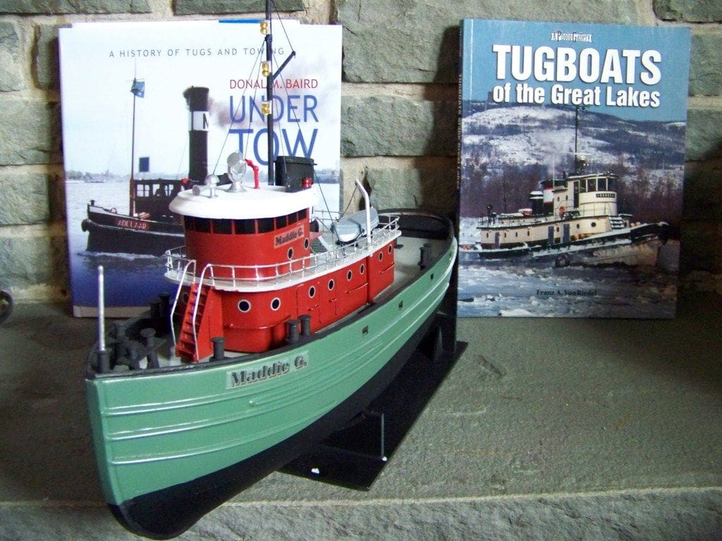
Building the Carol Moran, which I renamed Maddie G after my granddaughter, was a good experience for me. Although this is not intended to be a model review, I must say that the kit was an excellent project for my skill level and I was impressed with the tips and advice offered in the instructions.
I am very pleased with the results of this foray into an alternative to the stuffing tube and would recommend it to anyone building a tug or ship model. The prototype is probably not well suited to high speed racing boat drives, but a future version with a well balanced rotor, supported by good ball bearings, could provide the advantages of this approach (especially reduced friction) for high speed applications.

Carl A. Lloyd
Carl is a recently retired mechanical engineer and part-time artist. He lives in the Finger Lakes region of New York State and is fortunate to be close to the Erie Canal, which traverses the state from east to west, connecting Lake Erie and New York City via the Hudson River. He is relatively new to model boating, but has enjoyed his building experiences so far. As his name indicates, he has roots in Great Britain and would love to visit some day and participate in some of the model meets that take place there. He enjoys reading Model Boats magazine and eagerly anticipates the articles in each issue.