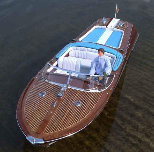
Jet-Riva Aquarama
BRIAN JOHNSON builds and modifies the Amati kit
Enjoy more Model Boats Magazine reading in the monthly magazine.
Click here to subscribe & save.
This is a 1:10 scale runabout, overall length 860mm and beam of 260mm intended for normal twin propeller propulsion, but because of my interest in water jets, I decided to modify it to this form of propulsion.
After the series of eight scratch built experimental airboats and water jet boats, the luxury of a quality kit allied to very attractive looks and the challenge of giving it a deep gloss finish led to this Riva Aquarama model. I was able to look at a neighbour’s standard Riva kit along with its twin-screw power pack accessory kit, but the thought of my sailing water with its vagaries of wandering weeds subject to wind and current made the model unfeasible. After much mulling, a flash of inspiration provided an ideal solution; why not modify the hull and fit a water jet unit to get the best of both worlds? So a phone call to Westbourne Models produced the kit and a Graupner Unit 6 water jet with a JP brushless motor identical to the previous work boat model. A leisurely look at the kit contents showed many hundreds of laser cut plywood items, lengths of mahogany and lime planking and chrome on brass fittings plus lots more. All very impressive and rather daunting, but the plans and a well illustrated 40 page instruction book with its 92 steps helped to allay any fears. To get the feel of the project and before any assembly or gluing, the conversion to jet drive had to be carefully considered, as space, strength, flotation level and performance were prime considerations; if these were generally resolved then it could hopefully be a clear run to a completed successful model.
Space and strength
The basic hull design has a deep full length keel pre-slotted to take eleven bulkheads and a long portion of its rear end would require total removal to allow for the centrally mounted jet unit on its base plate. New longitudinal members each side of the jet unit would replace the original keel to put strength and alignment back in to the hull. The only safe way, was to build the hull as per the plans and carry out the conversion later whilst trying to think of anything which could help, or hinder, the conversion. An EVO 14.8v 5350mAh LiPo battery would fit laterally between the rear of the motor and the raised seating area as this was the only available space for it, so the C of G would also require looking at later.
Flotation level
As there is no indication of this on the plans, the assumption was that the model would float approximately on the division line between the white wrap round underside of the hull and the vertical mahogany side finish. This was taken as about 40mm from the bottom of the vee hull which happily was similar to the physical height of the jet outlet centre line. This common static water line and outlet centre line was found to be the optimum on my previous water jet boats so luck was possibly in! Any great difference in weight would obviously affect this level, but the kit drive line comprising of twin MFA/Como Drills 3 to 9 volt motors with reduction gears, propshafts, tubes and rudder items totalled 495 grams. The assembled water jet weighed 425 grams and equivalent capacity battery weights appeared to be little different, so overall the weight factor was not important.
Performance
It is assumed that the kit drives were designed and supplied to produce a scale speed for this runabout type craft. Any gain, or otherwise, was impossible to calculate, but very rough assumptions of Amps and Volts showed an over 50% increase which may not be desirable, but then it is easy to throttle back if need be and yet also tempting to find the operating limits of the model.
Framework and conversion
The laser cut parts were broken out from the 3mm thick plywood sheets; the tiny nibs sanded level and it has to be said that all the parts fitted perfectly together. One lesson soon learnt, was that any poor fitting item was down to the builder and not the kit or the instructions. The kit is in the ‘Advanced Class’ of building, but painting by numbers is no more difficult as long as the plans, illustrations and sequence of operations are well studied and followed, or at so at least goes the theory. By securing the base area of the keel in a vice mid-way along the hull and at the rear end, all the bulkheads were glued in vertical and parallel using Evo-Stik Weatherproof Wood Adhesive throughout, plus five minute epoxy for other small but vital joints. This gave an accurate basic hull ready for the easy addition of more items. The 270mm x 80mm x 3mm jet unit base plate, similar to my previous models, was just long enough to enable the motor to be removed from its mount if an obstruction was behind it. One end had a vertical stern plate for sealing purposes and a laminated plywood tunnel to run through the sloping stern of the kit with a flange at the other end for mounting to any convenient hull member. Before cutting out the base plate, eight new side members were made from spare plywood and well glued into the framework. Laying the base plate alongside the hull showed 330mm of the keel and three bulkheads required removal which was quickly done by using a junior saw from underneath. The base plate end flange was secured to No. 7 bulkhead by M3 screws and the stern plate glued to the rear bulkhead. The steering nozzle projected through the sloping stern and was thus vulnerable to damage, so one of the 3mm propshafts and tubes supplied with the static kit was converted into a hoop with long tubes through the hull to provide protection and also be a useful carrying handle without unduly spoiling the appearance of the rear end. This completed the conversion which was far easier than anticipated and which enabled the standard kit construction to re-commence. These was mainly the top front deck members and internal items including the veneer linings, so it was back to gluing by numbers.
Planking
On page 25 of the instructions, Step 51, the dreaded word ‘Planking’ first appears. Now was the time to regret not reading or absorbing the magazine articles by experienced builders who have produced such masterpieces as seen in these pages. This model system is based on 7mm x 1.5mm Lime planks followed by a second layer of 8mm x 1.5mm Mahogany planks plus smaller sizes for the deck giving a total of around 180 planks. The instruction book shows the use of pins to secure the first layer of planks to the bulkheads. These high quality pins are 0.8mm diameter with fine ground points, but they do not enter the bulkheads easily. The instruction book also states: ‘As this is the first planking, great precision is not important’ which cheered me up no end, but to my amazement the first layer went on albeit slowly, but in good order. Thus in spite of the convex to concave hull lines very little sanding was required to provide an even surface for the outer mahogany layer. A piece of good advice in the book was to let the planks run free, i.e. no forcing them sideways. Any gaps towards the bow were filled in later with wedge shaped offcuts. The bow has a sharp point and the springy ends of the planks with a minimal gluing area were held in place with an adjustable height and angle vee jig mounted in a vice. Wood filler pumped into the nose void then helped to consolidate the area. The prow has to take a full height metal nose piece, so the offcut portion of the keel laser cut sheet was used as a template to obtain the correct profile. After the triumph of the first layer, the mahogany top layer looked to provide its own problems as the whole 850mm length for each plank had to have glue applied to its base area and along one edge to ensure good contact and water sealing. Some flat portions needed only masking tape to trap them down and level with the previous plank, but pins were needed for most curved lengths and all this was going on while the glue was gradually setting and my patience rapidly diminishing! Inserting pins through the fairly hard mahogany whilst trying to hold the plank in position was not easy and one alternative tried was to lay the dry plank in position, place small pieces of masking tape where pins would be used, remove the plank and drill 0.7mm holes at an angle at each masking tape.
After the plank was fitted, pinned and glue had set, the pins were pulled out and the holes filled with plastic wood as the tapes were removed, which ensured no holes were missed. A further attempt at direct pinning proved the mahogany could be pierced with a good push and without splitting the wood, so this method was then used. The Amati pin punch with its spring action was invaluable for this and speeded the whole operation. The euphoric feeling of actually finishing all the planking partly disappeared when I examined the finished hull which showed evidence of some planks proud of their neighbours, small gaps at tapered joints needing filling and the pointed bow was a mess where it met the deck edges.
The kit is at the difficult level for making and has been named ‘Model of the Year 2007’ in the past. It can be finished to museum quality, so my early assessment of a ‘painting by numbers’ level was shattered when planking was commenced.
Painting and initial fitting out
My recipe for a good finish has basically four maxims.
1) Fine sanding of all the planking and joints, so that only the plank graining defines the edges.
2) The use of best quality varnish (Le Tonkinois Marine No. 1 varnish self levels and leaves no brush marks).
3) A good quality brush somewhere between normal decorating and the finest artist’s types (Daler-Rowney System 3 acrylic brushes at medium prices are ideal, being soft and flexible).
4) Eliminate dust pimples, which are almost impossible to avoid unless painting in a sealed room and are impossible to remove, short of fine sanding right back to the previous coat. Only the builder can decide what is acceptable and my leaning towards general use as against static display helped the ‘opting out’ decision for this.
Fitting out
So, after a head transplant, homemade tunic and trousers, removal of the too small cap and some flat brown paint to cover the bald patch, all this completed the transformation into Gino!
Bath test
A final test was needed to settle the flotation height and level. This showed a slightly bow down attitude and the outlet nozzle centre line at 10mm above the water line level so ballast was definitely required. This was the penalty of fitting the battery in the only position available, thus altering the design C of G. The undersides of the two rear hatches were available to hide the cut sheets of 3mm lead and a total of 636 grams satisfied all requirements.
Sea trials
The high speed turns were positive and safe but Gino (the driver) was thrown side to side during these, so I suspected that scale speed had been exceeded. After quite a while of full and part throttle running the model was brought in and checked. Some water had once again collected inside the stern area for no apparent reason, but turning it upside down to drain and leaving the rear hatches off allowed it to dry out on its own. The motor was fairly hot, but not unduly so, and the controller was not even warm, so the model was accepted as being ready for the projected shoot-out with the standard kit version. The post-trial charge showed 859mAh remained, i.e. less than 20% of the battery capacity was in hand, so my liking for the larger, but heavier, battery seemed sensible at the time of buying, but not absolutely necessary.
Conclusion
The comparison of the standard Amati Riva Aquarama and this modified version will appear in this magazine in due course.