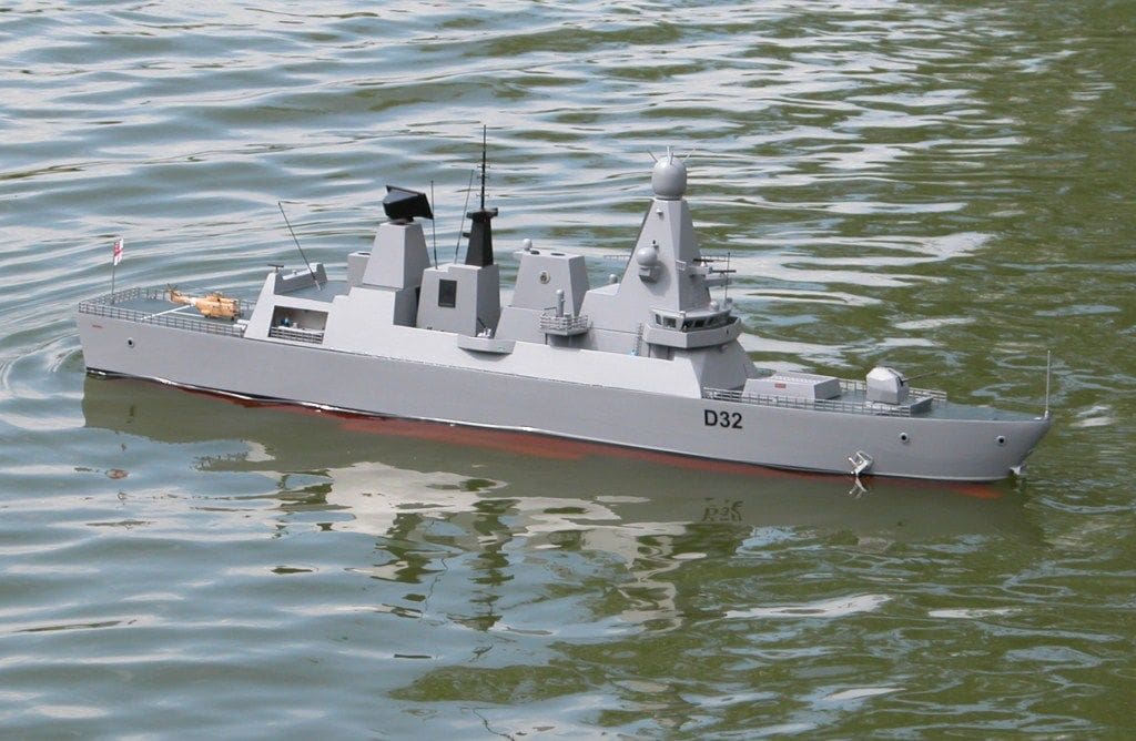
Tony Dalton describes his semi-scale model
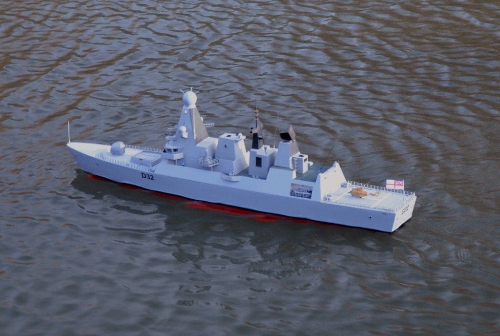
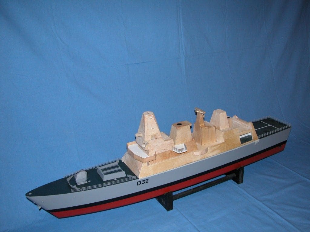
On my retirement, like most people I reverted to gardening and doing jobs around the house, including decorating. It did not take me long to get bored with that, to which end I re-kindled an interest in my old hobby of model making. I retrieved the old models from the loft, started taking Model Boats magazine and joined my local club, the Luton and District MBC. Thus, I had found an interest to keep me happy in my retirement years. Having completed all the cleaning up of my old models, my thoughts moved towards what new projects I could undertake. I had seen a model of a frigate (Paladin by Glynn Guest) built by a fellow club member Peter Carmen, the plans being published in MB October 2005. Not being one to copy another member’s model I considered what similar models I could build. At that time a lot of media time was being given to the new toy the Royal Navy was getting, namely HMS Daring, for which I duly searched the internet and found the BAE Systems website with all the information I could ask for in the form of artist’s impression of the vessel. I then set about drawing the model that I intended to build from these artist’s impressions. The scale chosen was 1:128 which produced a vessel about 1.2 metres long. The following article is not just a story of building the model of HMS Daring but also of the problems encountered and its ensuing development.
During my investigation into HMS Daring and in particular the methods of propulsion the BAE website referred to ‘Wartsila’ and that engine manufacturer’s website described a system of propulsion pods under a vessel with no conventional propeller shafts, thus my thoughts moved to using a jet drive system. I should mention that the actual vessel had not been launched and until it was, I did not discover that it had in fact got conventional shafts and propellers. Unfortunately by this time I had completed the hull and was well on to completing the superstructure and therefore decided to leave the build of the vessel as it was. So, a jet drive HMS Daring it was, and a big lesson learnt from incomplete research!
Enjoy more Model Boats Magazine reading.
Click here to subscribe & save.
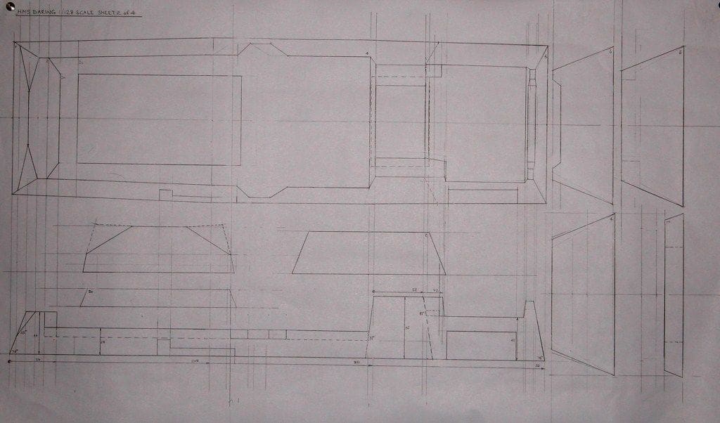
Plans and basic work
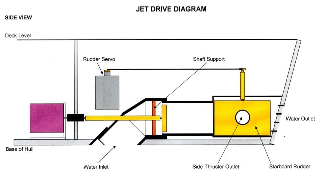
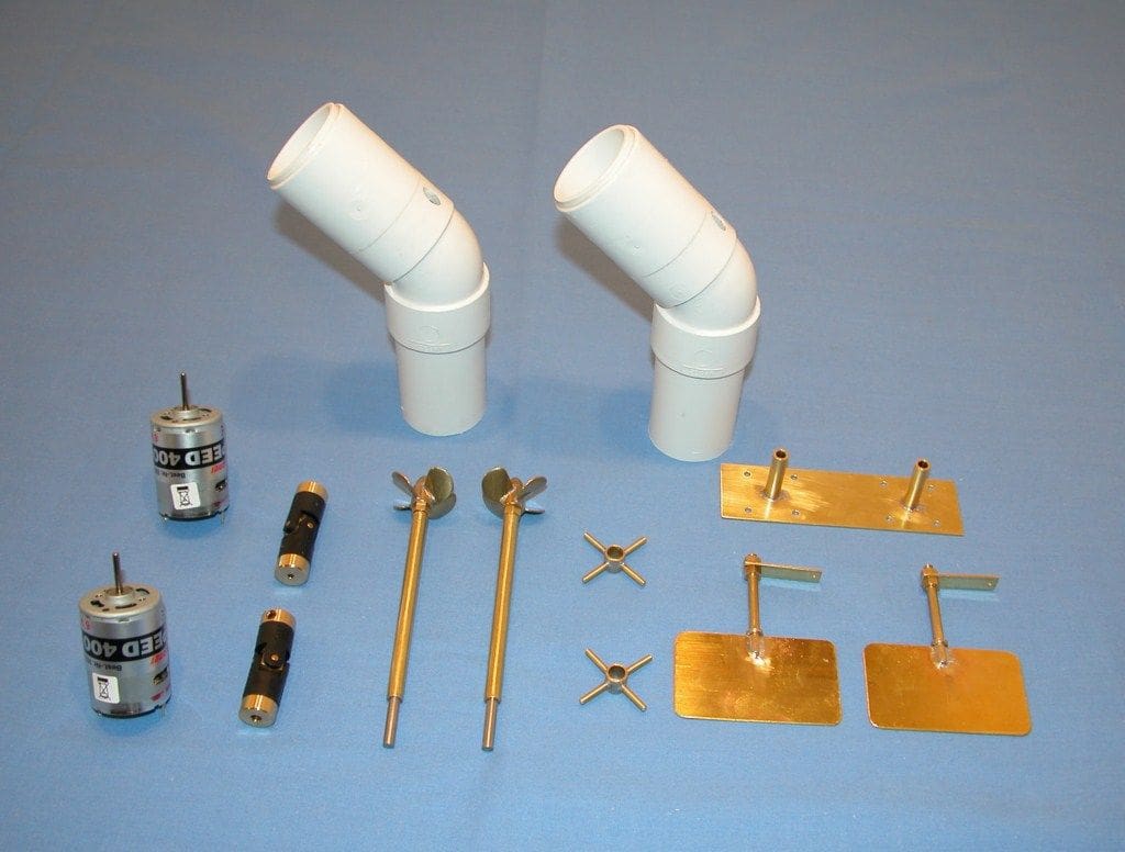
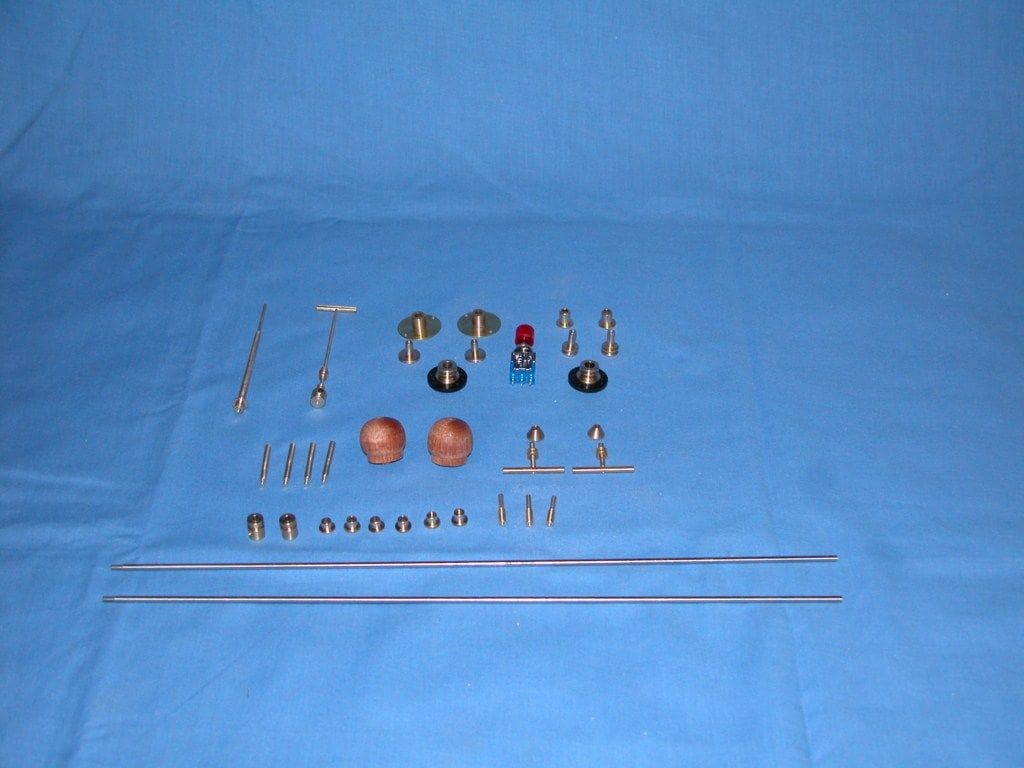
As mentioned earlier I drew up my own plans for the hull, superstructure and jet drive propulsion system, an example of which is Photo 1. The design concept for the jet drives is in Photo 2. You will notice in this drawing that there is a hole in each side of the propulsion boxes, which house the rudders. When a rudder is at its extreme of angle, some of the water thrust from the jet drive is channelled through these holes which act as side thrusters thus aiding the steering of the vessel. Photo 3 is of the prepared jet drive parts.
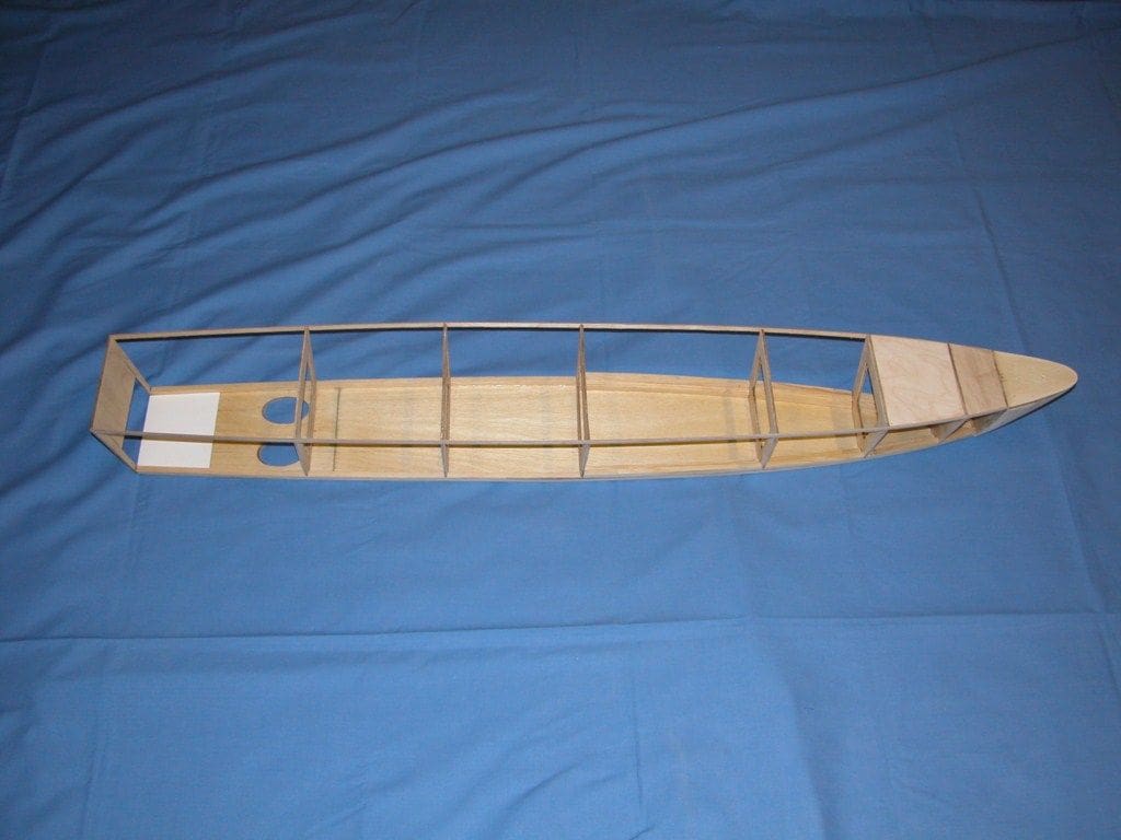
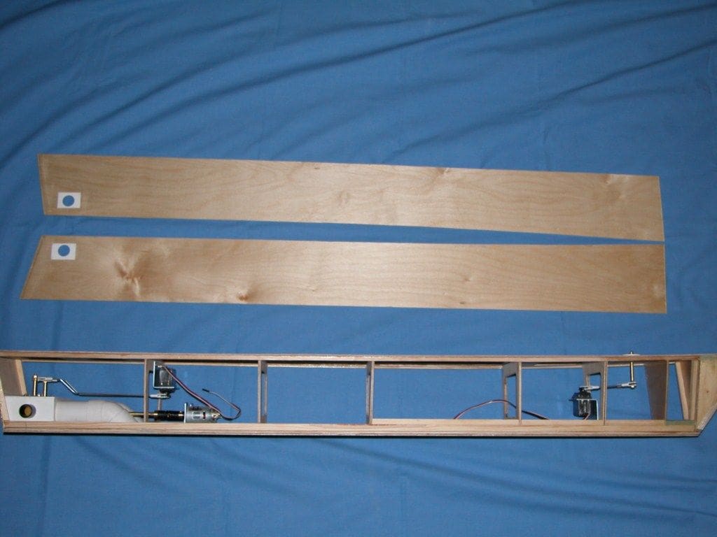
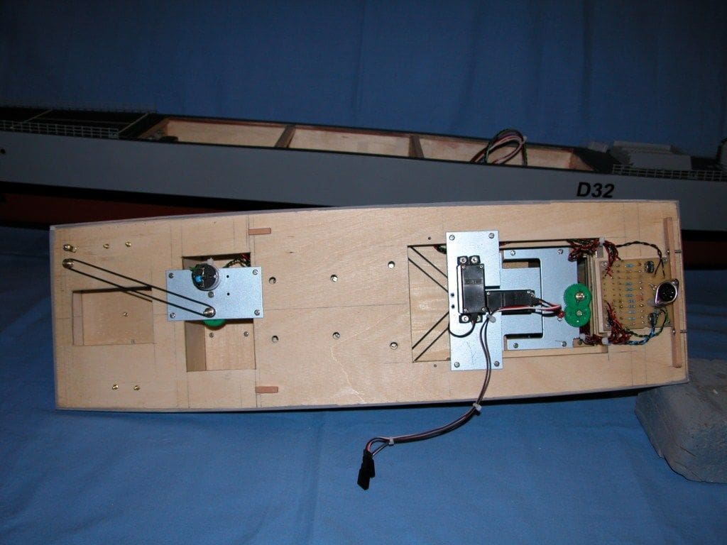
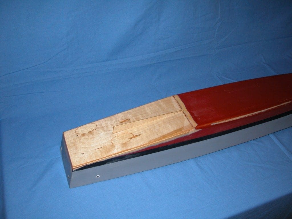
The assembled hull framework can be seen in Photo 4 and the two large holes in the bottom of the hull are for the jet drive intakes. Photo 5 shows the hull with the sides ready for bonding into position. At this stage, the propulsion system, rudders and gun rotation servo have been installed, which is much easier before the hull sides are added.
Photo 6 shows the hull in the process of being painted after the deck had been fitted.
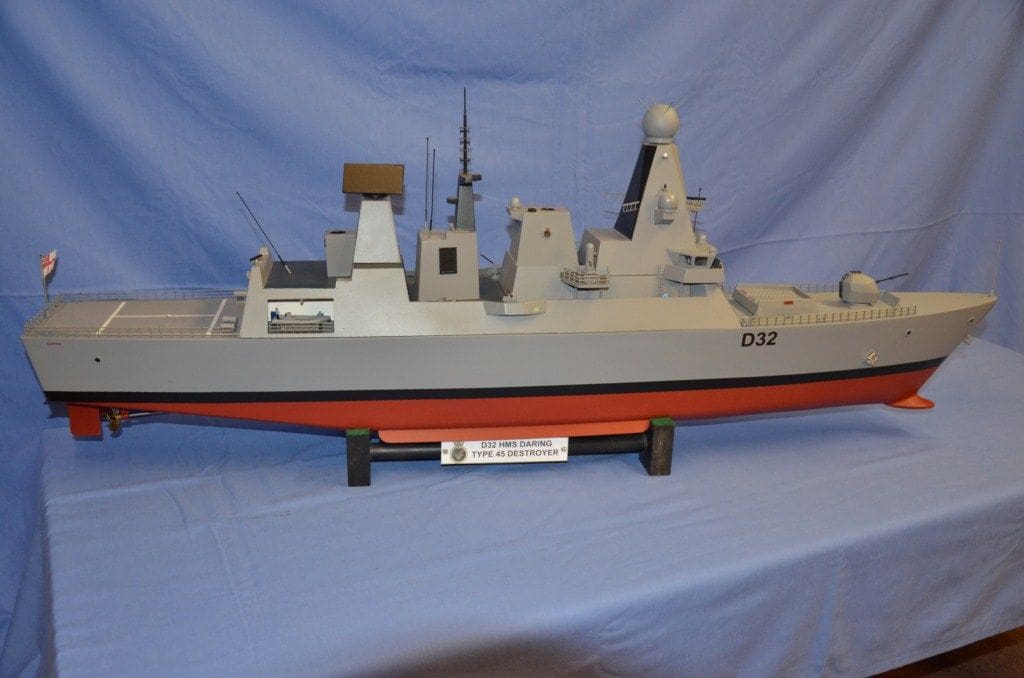
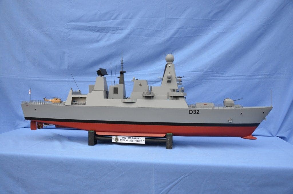
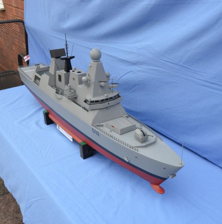
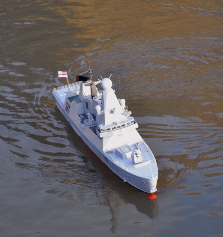
All this was straightforward work. The model was only intended to be semi-scale, hence simplified wherever possible, but maintaining the appearance of a reasonable Type 45 destroyer representation.
Superstructure
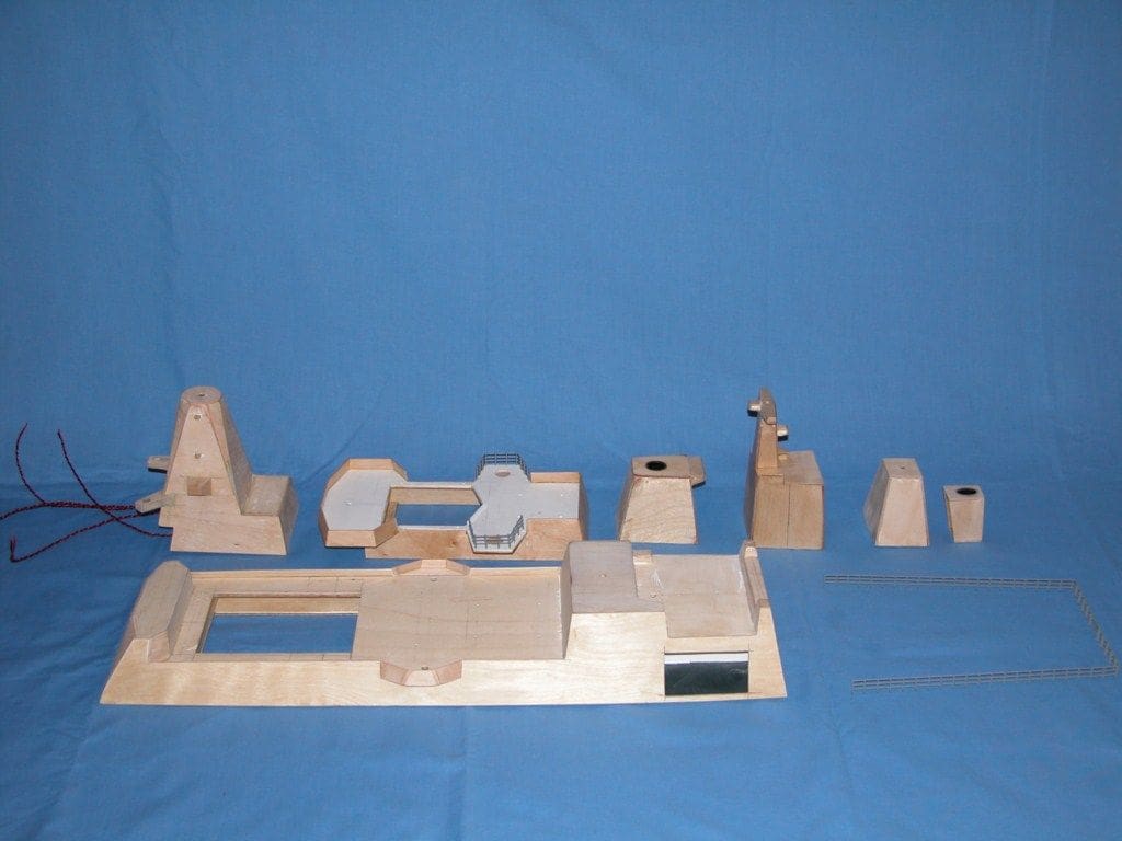
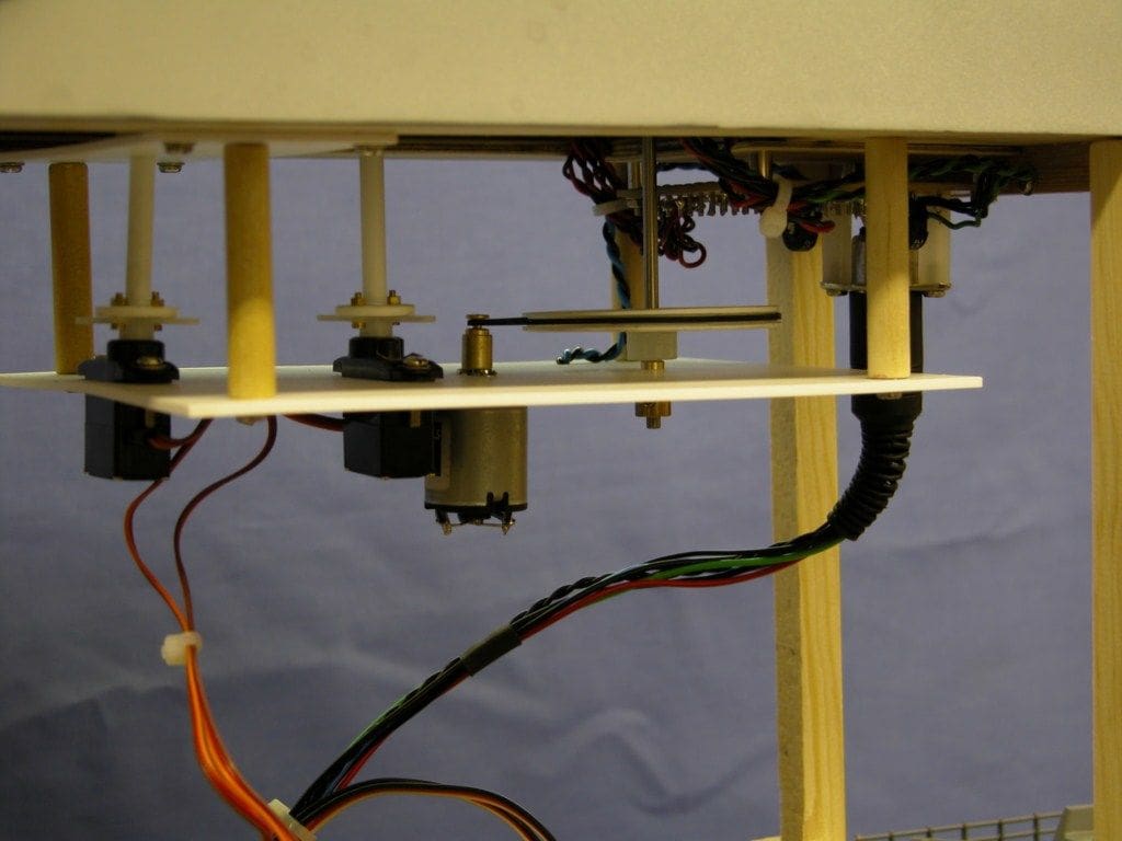
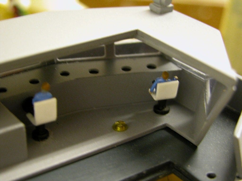
Having now completed the hull, my building efforts turned to this part of the model. I wanted the radar antennae to rotate and the guns to sweep in an arc. The Phalanx CIWS guns are mounted on platforms that protrude beyond the main superstructure and this posed something of a problem in getting a drive system to them. The way this was solved was to make the upper deck a sandwich comprising a centre core of 2.5mm plywood between two thin sheets of 0.5mm ABS styrene card forming the outer covering. Part of the inner core was then cut away to allow for a belt drive which would rotate the guns. Some of the pulleys and associated radar parts can be seen in Photo 7.
The superstructure was made from mixture of plywood and ABS styrene sheet and Photo 8 is of part of the completed, but unpainted superstructure. Some of the navigation light wiring can be seen protruding from the forward part. Photo 9 is of the complete superstructure unit in place.
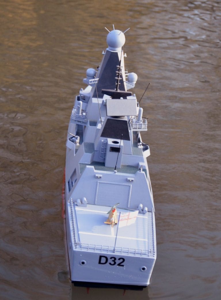
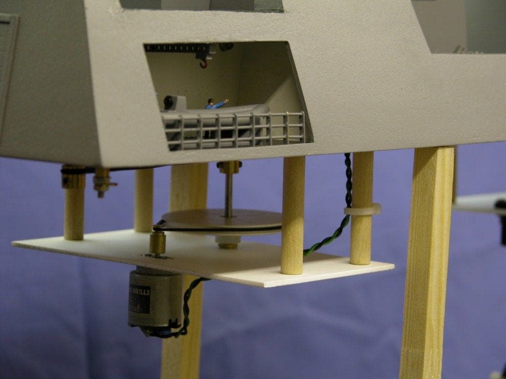
The first design of the Sampson radar drive system comprised a small electric motor driving the rotating ball via an all plastic gearbox housed in the upper superstructure, Photo 10. This in fact proved to be far too noisy and heavy, its weight making the model unstable because of its position high above the waterline.
The solution was to lower the drive system well below the main deck line on what could be called a sub-chassis mounted on pillars beneath the deck and also changing the system to belt drive. These belts came from some old tape recording systems and are still available from radio repair and component retailers. The new completed belt drive system for the Sampson radar and forward gun is shown in Photo 11 and Photo 12 is of the after radar rotation system.
Further detailing
Having built the main parts of the superstructure, I decided more fine detail was required. For the bridge, Photo 13, I built a control console with LED lighting installed to illuminate the instrument panels together with interior general lighting. Crew members were also installed on small seats in front of the consoles.
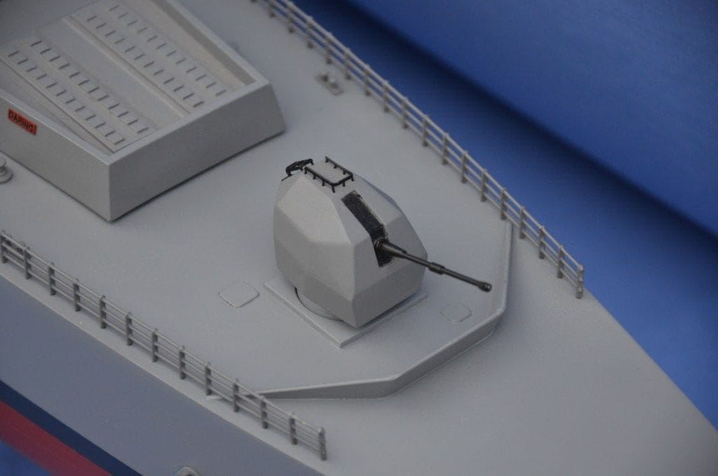
The construction of the 4.5 inch gun, Photo 14, was more difficult. Initially I tried to build it by creating a working plan, printing it all out on card and then cutting and folding it into shape, but this failed miserably!
So, it was back to a block of balsa wood as a former, roughly cut and shaped to match the working drawing. A shaped 0.5mm styrene base was cut and bonded to the bottom of the balsa block after which the wood was sanded to the required shape. As each face of the block was sanded to shape, a new piece of styrene was cut to size and bonded to the block, eventually completing the turret. The base was drilled and a boss inserted to take a shaft which would protrude down into the hull and connect to a servo. The barrel was made from brass tubing and the handrails added, these being made from a small section brass ladder cut in half, Photo 14.
The other two types of gun are fitted to the upper decks and can be seen in Photo 15. These were constructed using styrene, brass tube and wooden dowel. As mentioned earlier the CIWS Phalanx guns traverse, operated by servos mounted below the deck.
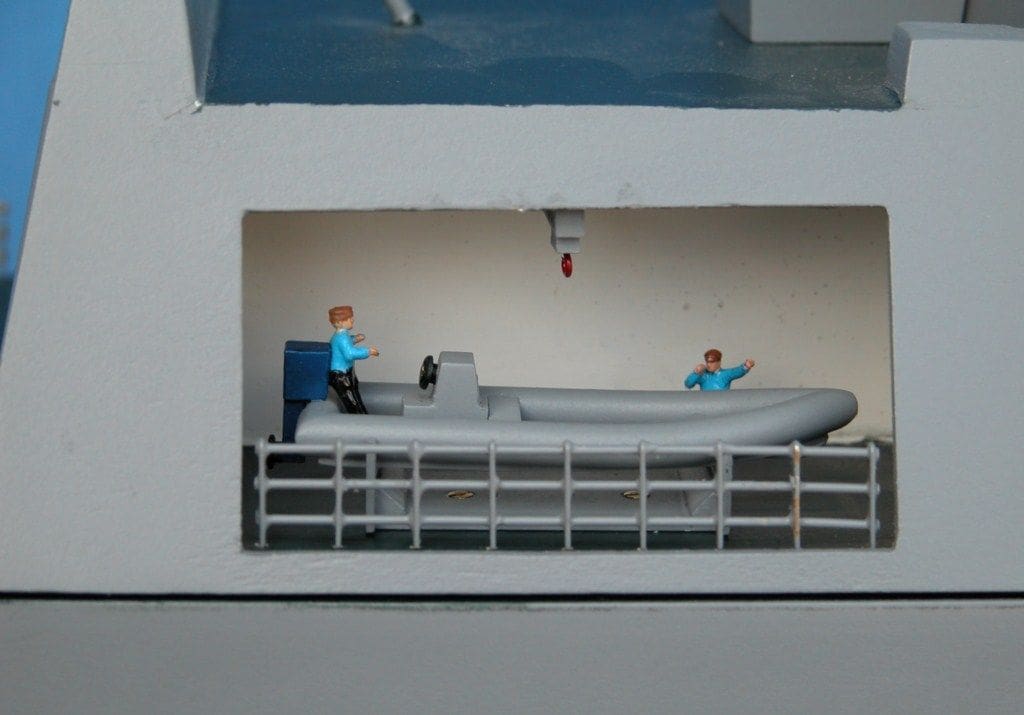
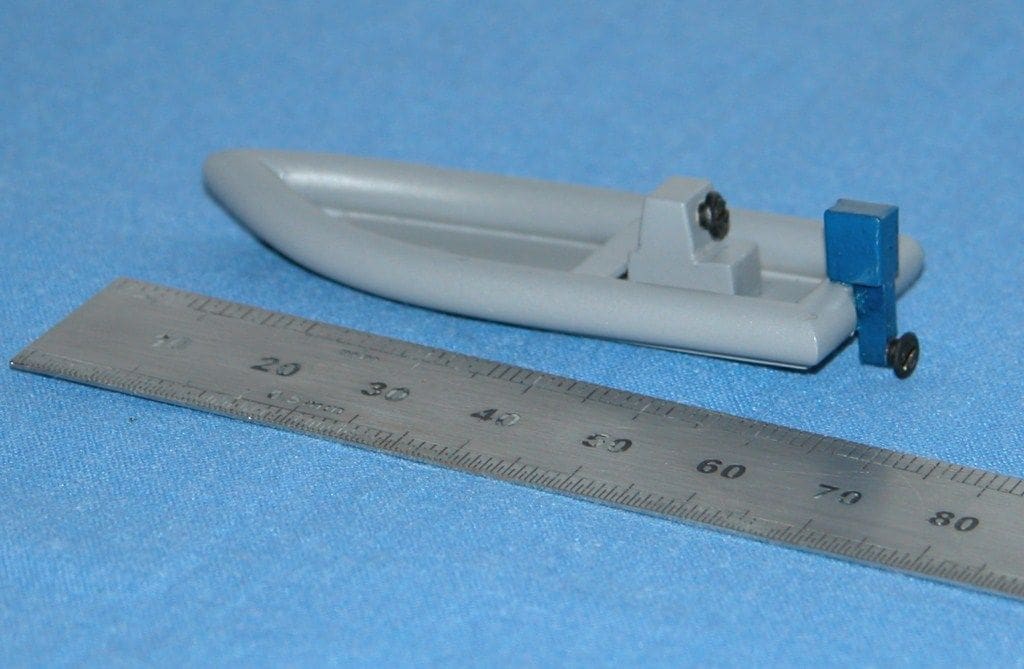
Both the recesses either side of the hangar have RIB’s (Rigid Inflatable Boats) installed, Photos 16 and 17. These RIB’s were made from ABS styrene tubing bonded together using a piece of 0.5mm Plasticard (styrene) for the hull bottom and blocks of styrene cut to form the control console and outboard motors.
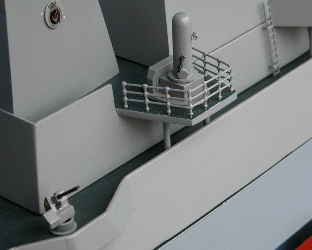
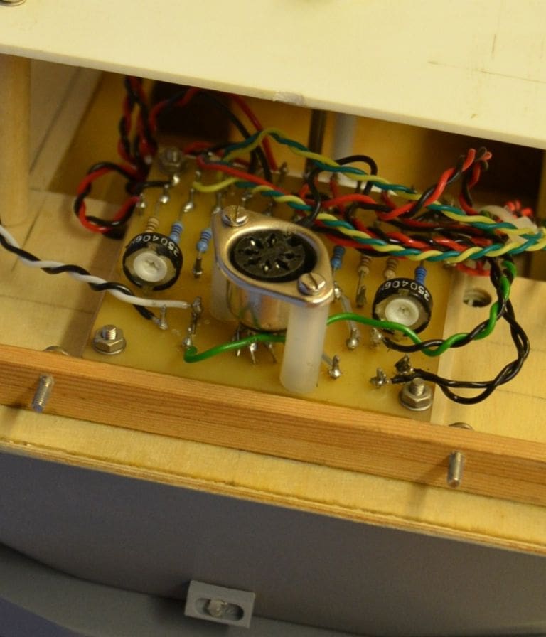
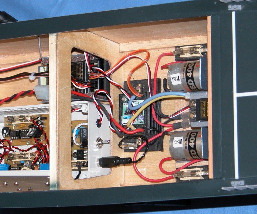
Lighting is provided using 3mm LED’s and the series resistors for the LED’s are all mounted on a central printed board mounted just below the bridge. Photo 18. Power for the lights and radar motors is fed from the control system via a multi-way cable up to this central printed board. A three stage electronic switch was constructed to sequentially switch on the lights by radio control: First; the navigation and bridge console lights; then the cabin and hangar lights; and finally the foredeck and helicopter deck lights.
The rotational speed of the radar is not only controlled by reduction gearboxes, but in addition there are two home built speed controllers to reduce the speed of the two motors driving the two radars.
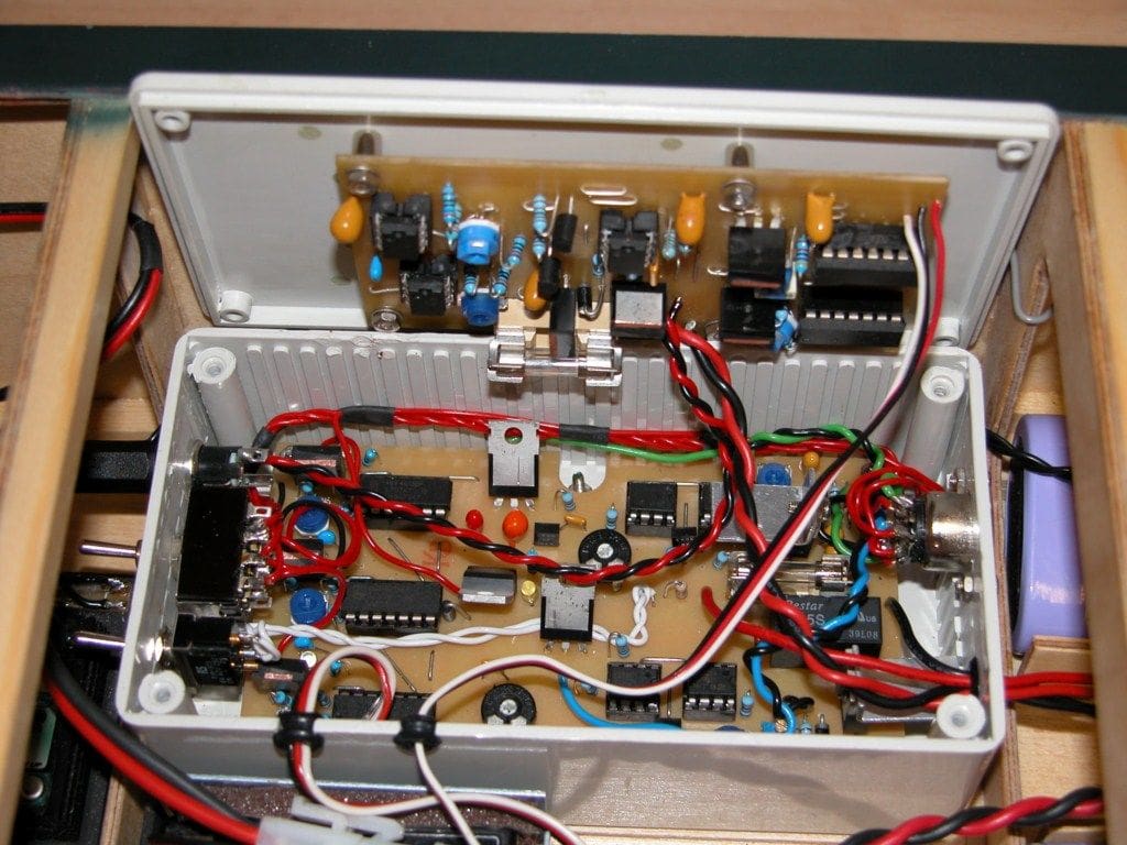
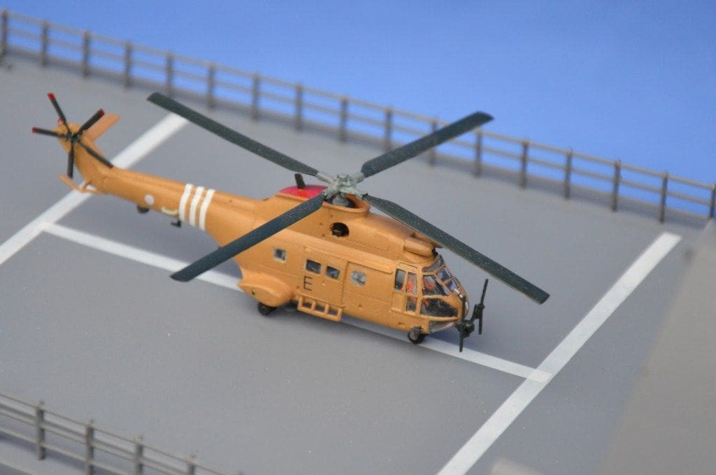
There is a home built sound system which produces a ship’s horn sound and the famous ‘whoop, whoop‘ destroyer siren all controlled by r/c. Photo 19 shows the electronics box with its three way switch, the radar motor speed controllers and the sound card. A 1:144 scale Puma helicopter painted in army ‘desert’ colours, Photo 20, provided the airborne interest since a 1:144 scale RN Lynx is hard too come by. This model was modified by installing a small motor to rotate the main rotor blades and very small LED’s for its lights. Two small pins protrude from beneath the fuselage and plug into sockets fitted into the flight deck to connect everything together.
Running gear
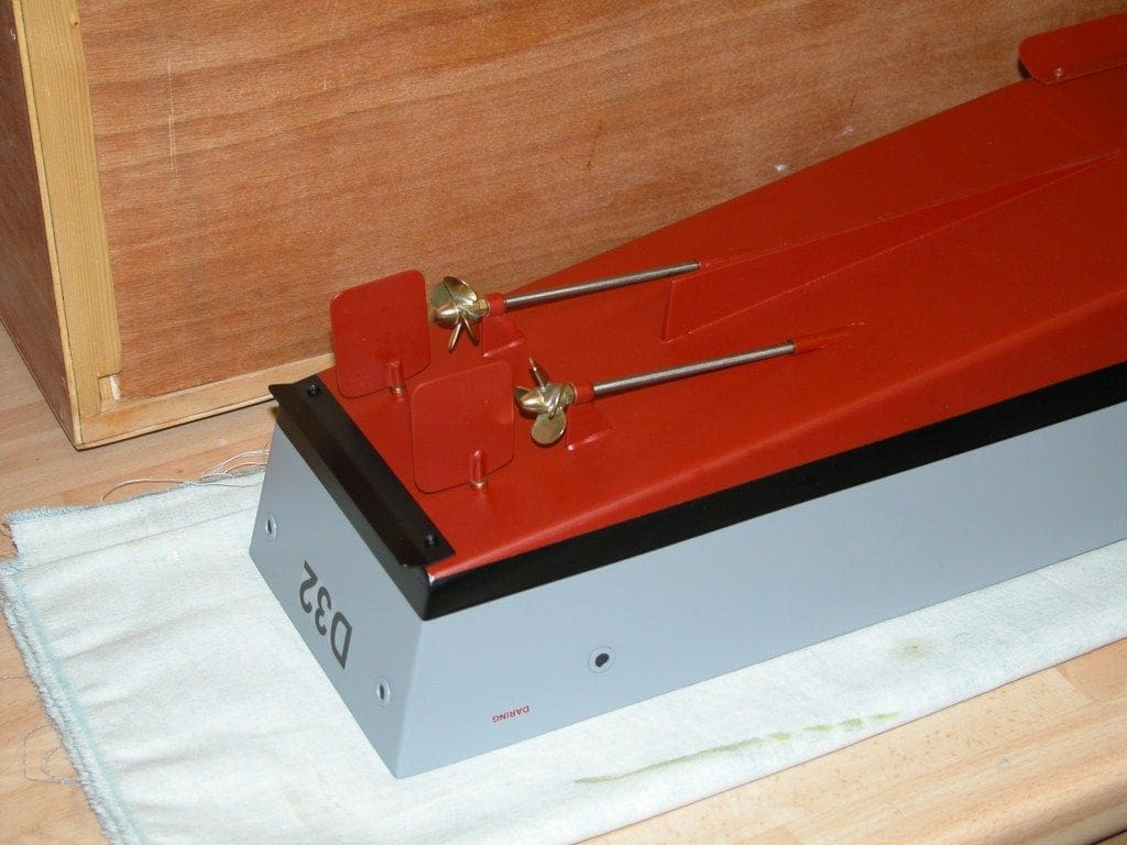
The jet drives were powered by Graupner Speed 400 motors controlled by a single Mtroniks 20 amp esc driving 30mm four bladed brass propellers housed within the jet tubes, Photo 21. Radio control is with Futaba equipment.
First sea trials and modifications
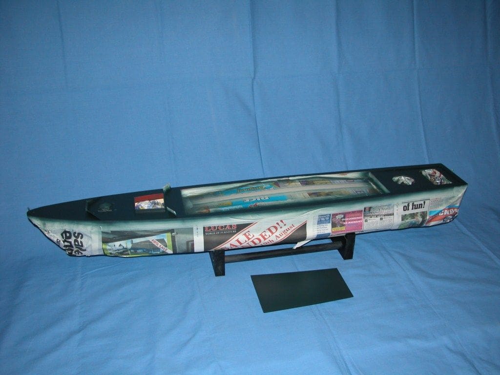
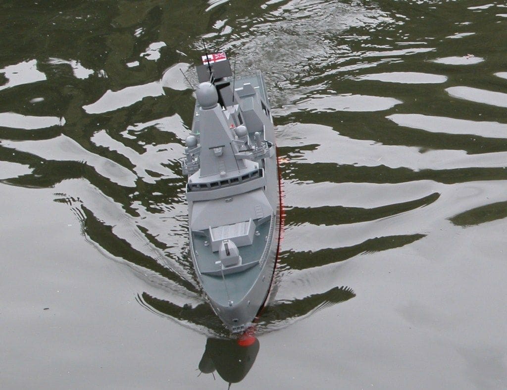
Performance turned out to be quite satisfactory with the side thrust jet drive system functioning extremely well, Photos 22 and 23. You may be forgiven into thinking that the project was now completed, but I am sorry as you are mistaken. The error about the propulsion system naggingly annoyed me, so after a time spent thinking about it, I finally decided to modify the model and fit two conventional propeller shafts.
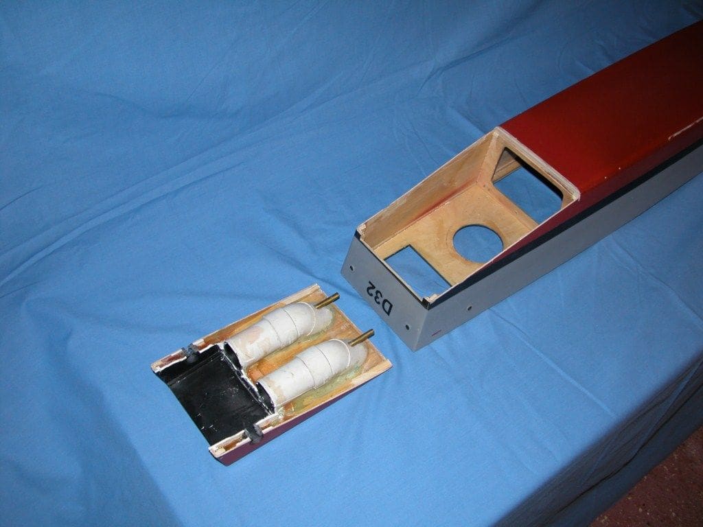
The first step was to remove the superstructure plus the small fittings on the main deck and then to remove the motors and r/c electronics. The hull was then inverted and the lower aft section cut away complete with the old jet drive system as in Photo 24. All rather drastic, there now being no return!
The next step was to cover the opening in the hull with plywood and add guide blocks for the rudders and the propshafts, Photo 25. New rudders and propshafts were then fitted and bonded into position and the hull repainted. Photo 26.
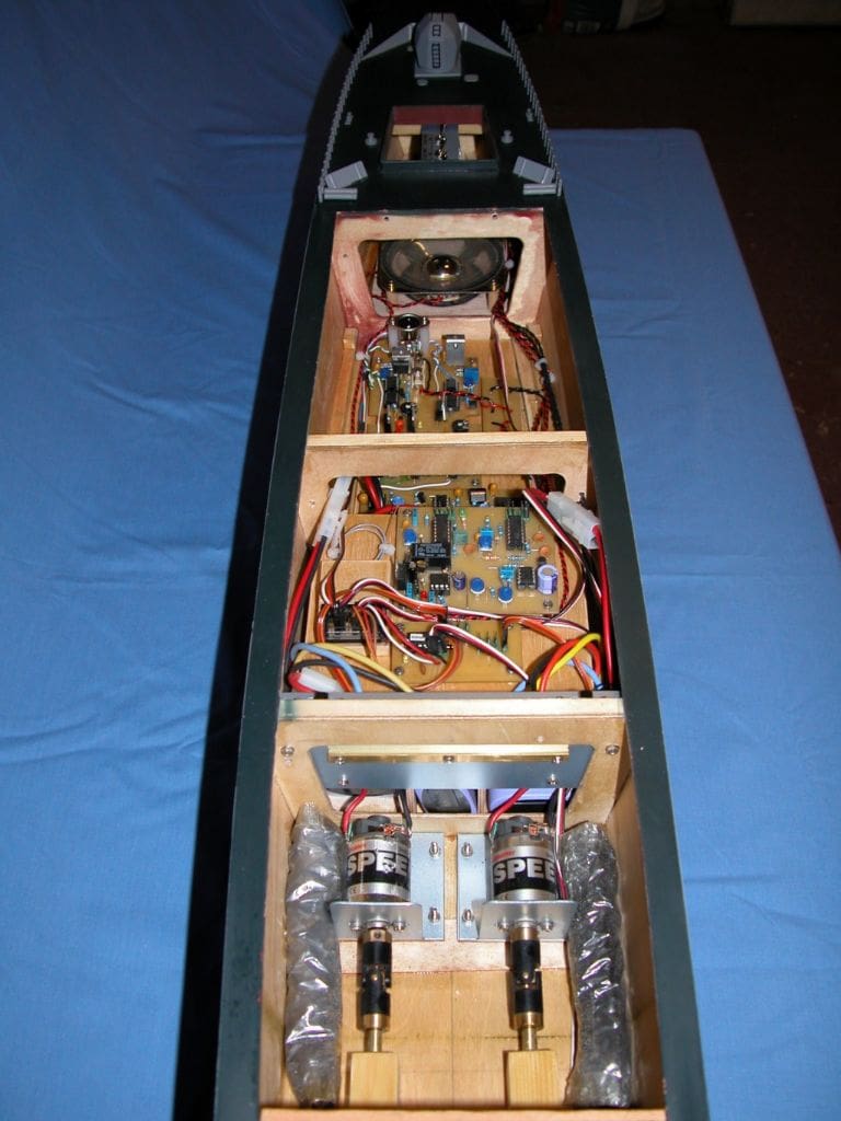
Two motors and esc’s were then installed and the opportunity also taken to revise the layout of the electronics system. A new electronic circuit was added to provide a slow traverse for the guns, with an option to automatically traverse every 30 seconds or control the movement by r/c. The revised hull internals can be seen in Photo 27.
Another problem!
The model was then bath tested, but by cutting away the box-like bottom rear section of the hull, the model was now somewhat unstable. Increasing the ballast helped, but then the hull was sitting in the water well below the marked waterline. So that was my day ruined!
The short term answer was to fit a small keel under the hull and this did function and it corrected the instability issue, but I was not happy and consequently this HMS Daring model was restricted to non-sailing duties for a time.
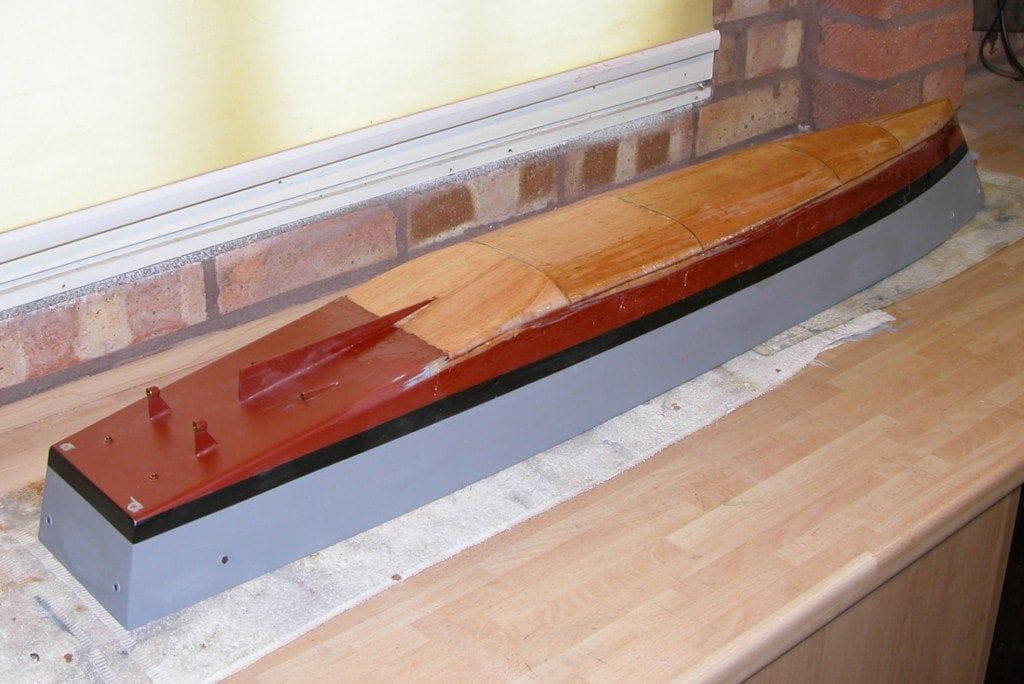
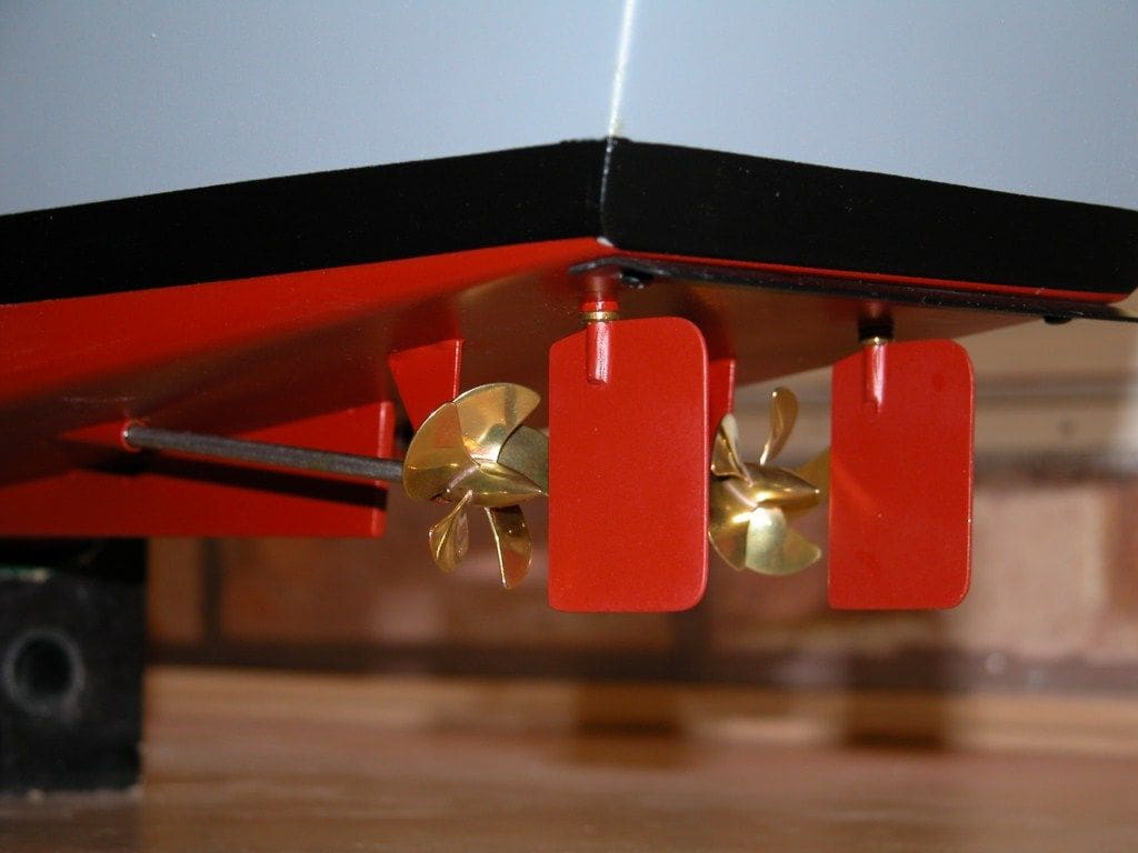
After a delay of another 12 months or so and giving the design flaws some serious consideration, the only answer was to increase the depth of the hull by about 20mm thus allowing an internal increase of ballast. So yes, yet again, off came everything and the hull was upturned for more butchery. Using a micro mill the underside of the hull was machined away between the bulkheads. Some extension bulkheads were made and bonded into position on the hull bottom below the existing bulkheads, and covered with a mixture of ply and balsa planking, Photo 28 which was then sealed with a lightweight cloth and GRP resin.
Yet again the hull was repainted and new five bladed propellers fitted, Photo 29. As a result of increasing the hull depth and therefore its overall height, the stand also had to be modified to allow the vessel to be fitted into its box. The list went on and on!
Other modifications included making a lighter Samson radome from a table tennis ball covered in GRP resin and cloth and the r/c installation was further lowered in the hull to improve stability.
Conclusion
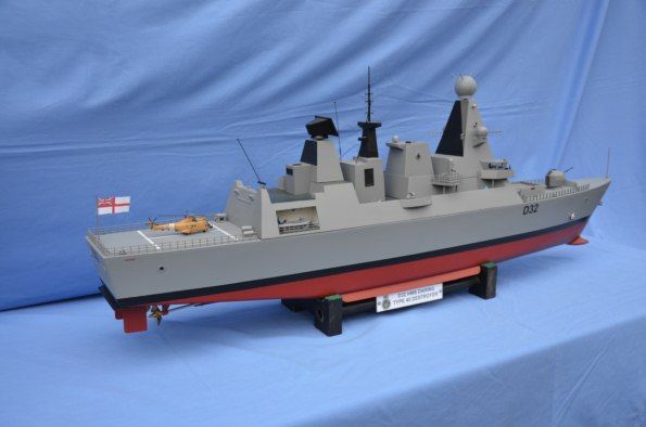
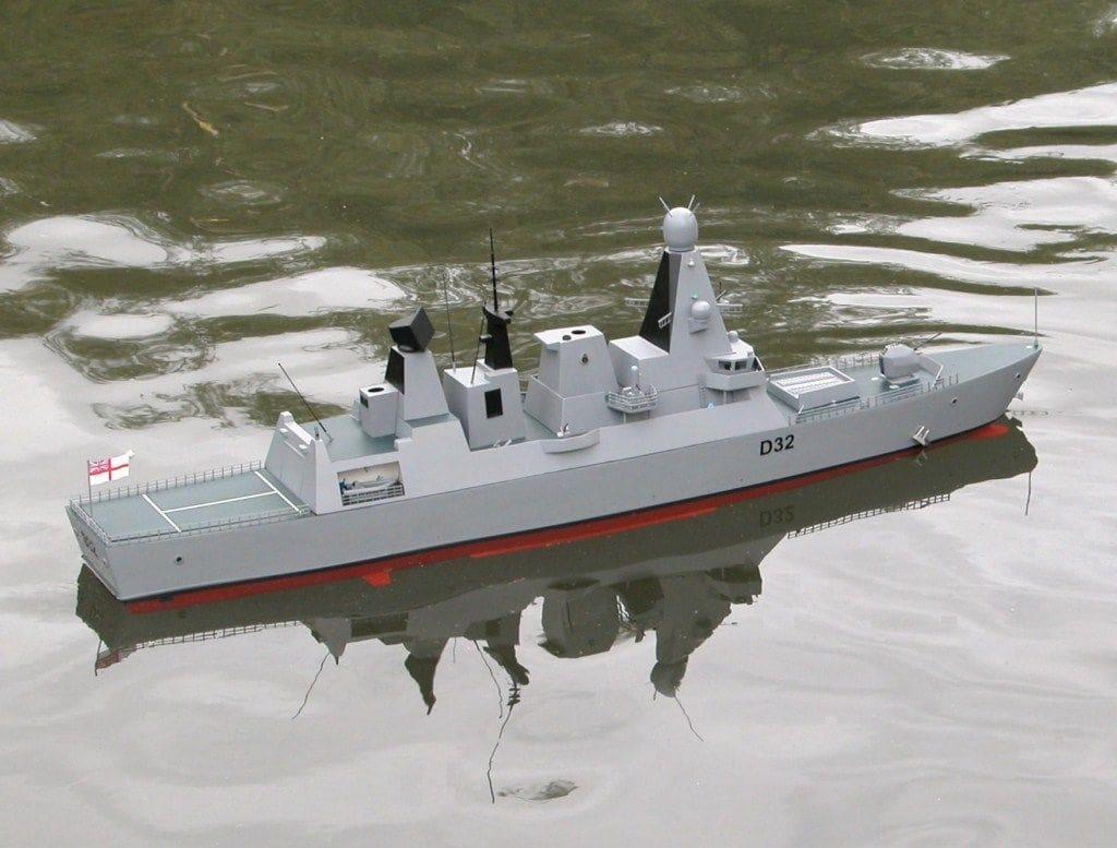
The result was finally a nice stable model with proper conventional pro-typical propulsion, Photo 30. Yes, it is not true scale, but I am happy with it and have learnt much about model design and theory along the way.
The moral of this story is do not take anything for granted when doing research and when modifying, bear in mind that any modification, although on the face of it straightforward, can itself cause more problems. We all live and learn by our mistakes, but much good has come out of them.
Happy model making……..!