RAY OLIVER converts the Deans Marine HMS Solebay kit.
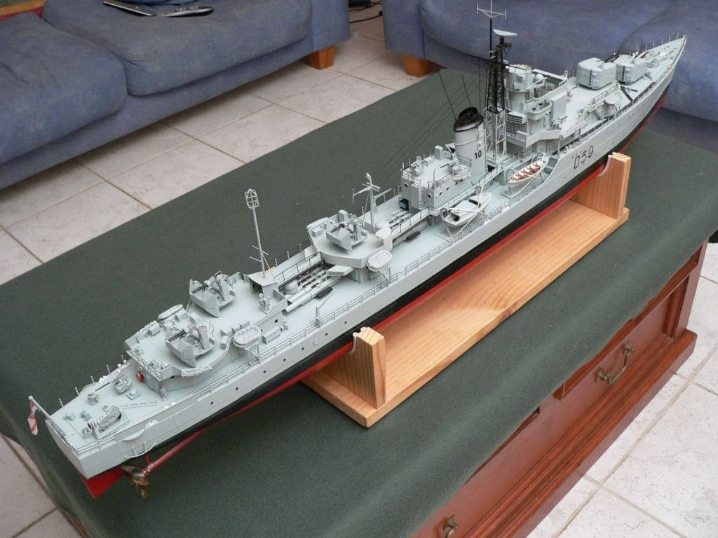
This is not a ‘blow by blow’ photographic record of my building this model (if only because I didn’t take very many during construction), but I hope the pictures of the painted and complete model will provide inspiration to readers who wish to create something a bit different from the standard ex-box kit.
History
Enjoy more Model Boats Magazine reading.
Click here to subscribe & save.
My interest in the Australian Battle class destroyers and HMAS Anzac in particular dates back to my Navy days. I served in big ships, notably the aircraft carrier HMAS Melbourne and the tender HMAS Stalwart, but I have always had a fascination for destroyers. During long nights at sea I would relax by reading books. One of my shipmates introduced me to Australian author and ex-naval gunnery officer, J.E. MacDonnell. His stories detailed life aboard ‘the boats’. I served on HMAS Melbourne for three and a half years and was on deck for most of the flying operations, so I had the opportunity to watch the escorting and plane guard destroyers as they manoeuvred round us.
The next ship I served in was HMAS Stalwart and as it was our job to provide support workshop facilities to the fleet when they were away from home, I was lucky enough to get to visit quite a few other ships, including destroyers. After I left the navy and moved to civilian life I didn’t think too much about Mr MacDonald and his collected works until many years later when sorting out my bookshelf. I rediscovered his books and delved once more into the world of Dutchy Holland, Captain Sainsbury and their colleagues. Dutchy Holland, one of the main characters, captained a fictitious Australian Battle class destroyer called HMAS Jackal.
Out of curiosity I started looking up images of their various ships on the internet and discovered that Australia had actually had two Battle class destroyers, HMAS Anzac and HMAS Tobruk. I know what you are thinking? Ex-navy and he didn’t know that, but I served mid-70s to the early 80s, so they were before my time. I loved the look of these destroyers and after seeing pictures of them they quickly become my favourite and I decided I had to have one. I had owned a radio controlled yacht since the late 1980s, but it was not until early in 2005 I ordered the 1:96 scale HMS Solebay kit from Deans Marine through R2 Model Marine. It took about eight weeks to arrive from the United Kingdom and when I collected it I was like a kid with a new toy.
The kit
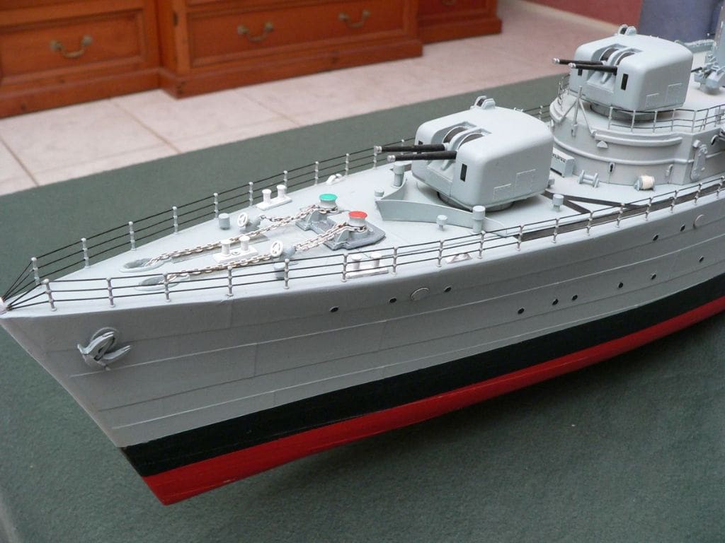
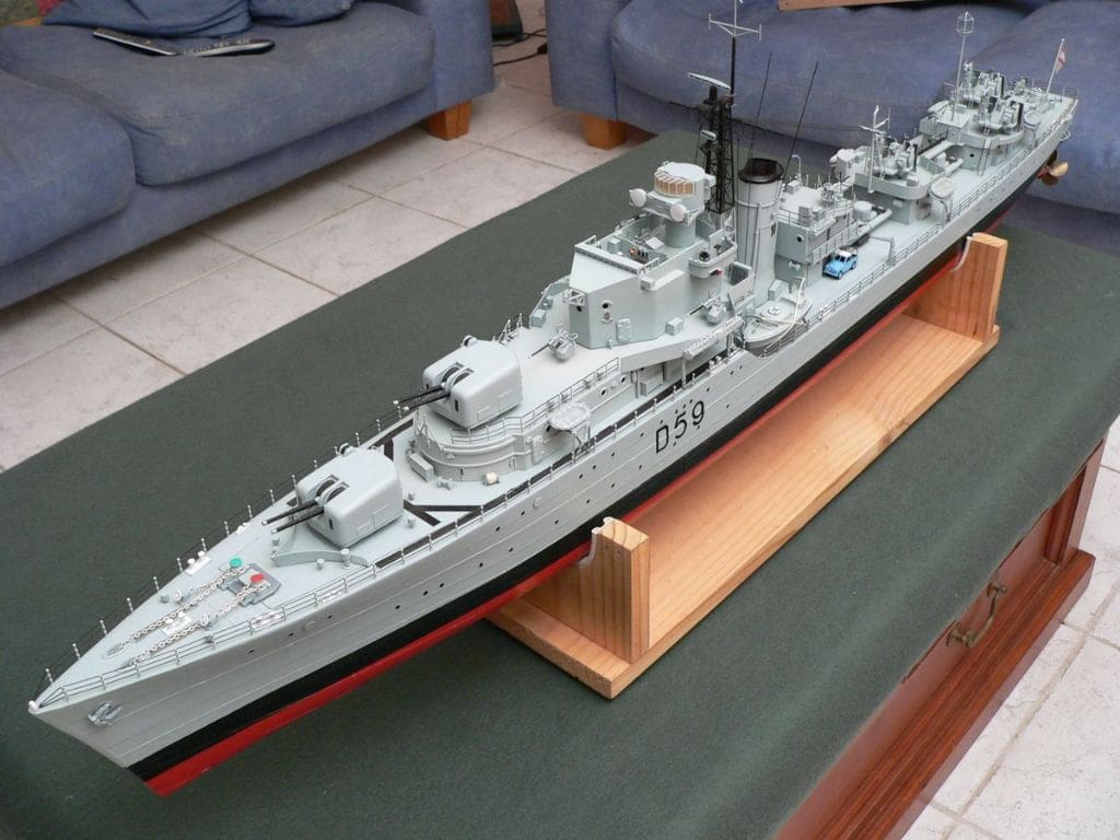
When I removed the packing to reveal the GRP hull, the first thing that caught my attention was the detailed hull plating. In spite of the journey there was little damage, just a small crack on the starboard side at deck level that was easily repaired. The positions of the holes for the propeller shafts were clearly marked, as were the bilge keels. The model is 120cm long by 13.5cm beam. The only preparation I had to do was to sand the top edge to the correct level and give it a wash to remove any residual release agent.
The parts trays were only covered by tape so I decided to put all the parts in to plastic segmented boxes with lids on them so I wouldn’t loose anything, I also made a new parts lists that corresponded with the new trays. I then took the instructions together with the reference material I had collected and placed it all in a plastic sleeve folder and I was ready to start.
Getting started
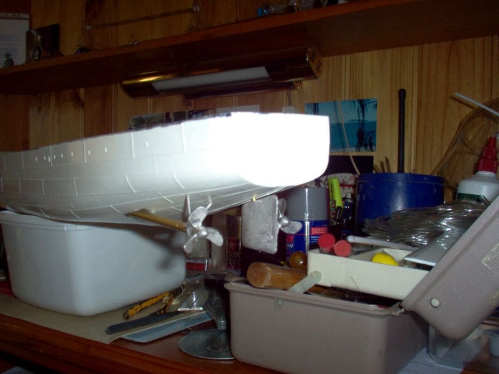
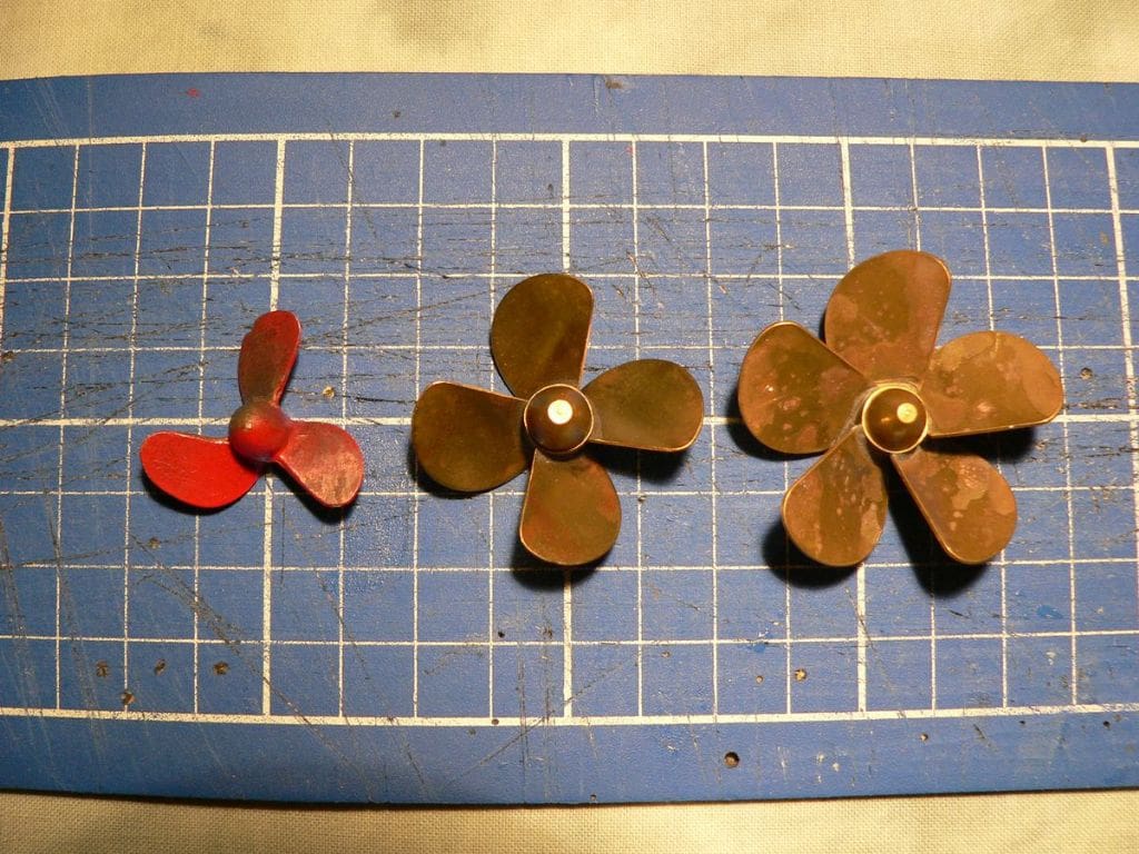
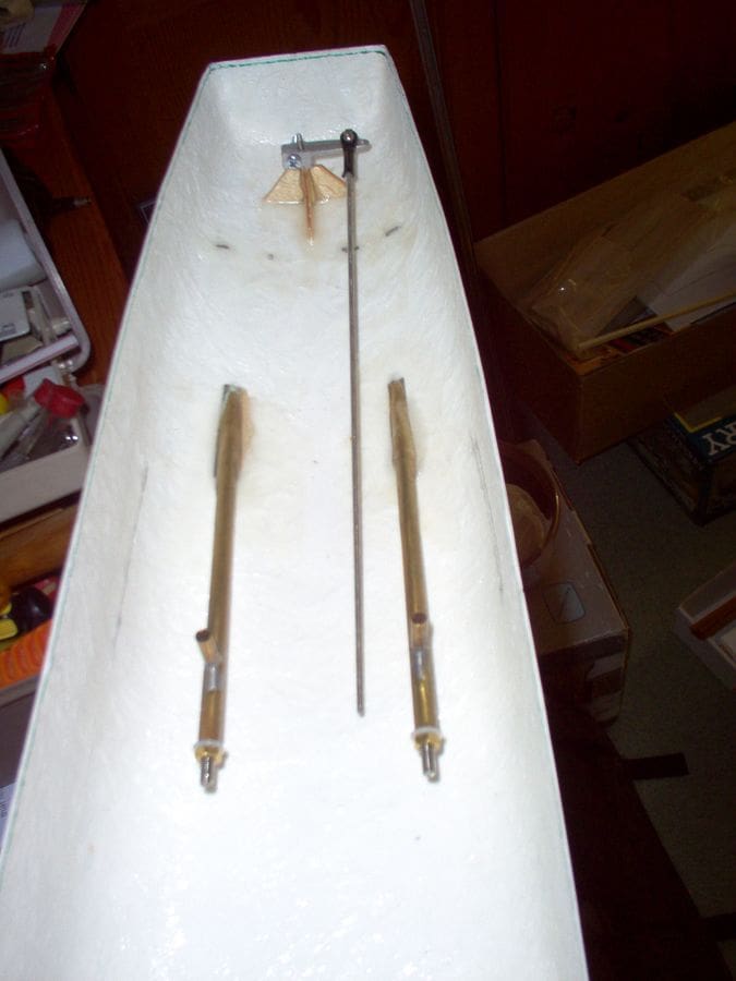
The first task was to install the propeller shafts and rudder post. This was easier than I expected. The holes for the propeller shafts were drilled and opened out and the tubes lined up with the A frames. Everything was then secured with masking tape and spot glued in place. Once satisfied, all the joints were reinforced with fibreglass resin. The white metal propellers had rather thick blades and they were thinned and reshaped. The white metal rudder also received some attention before painting.
With the propshafts and rudderpost in place I turned my attention to the supporting structures and framework inside the hull. The instructions were a little confusing at first but the more they were studied then the more sense they made. All the internal woodwork was soon completed ready for the deck, but some of the working parts were installed before the deck was fitted as access was going to be limited once it was in place.
The deck was cut slightly oversize then trimmed until it was a near perfect fit. The cut-out sections for access were simply easily removed. With the deck installed and the entire model painted in grey primer I moved to the test tank (swimming pool) for buoyancy and ballast tests. This went well and established that the model needed an all up weight of almost 4kg to float at the waterline. Most of this would be the batteries with some pieces of lead that I could move around for trim purposes.
Disaster!
That first test day was bright and sunny with a temperature of about 26 degrees C and within a couple of minutes the deck that I had so carefully cut out and fitted had buckled in the heat. This was obviously unacceptable and I concluded that the best plan would be to replace the deck with 3mm plywood. This produced a light strong deck and also allowed the access holes into the hull to be a little larger. The task of removing the old buckled deck was a slow and tedious business, but I was able to save the breakwater from the forecastle by carefully cutting round the front edges and straight across the back. This left a triangle of plastic to which the breakwater was attached. but when installed on the new forecastle with ‘A’ turret and other deck fittings in place, the step behind the breakwater is almost invisible.
It took a couple of weeks to complete the plywood deck before I was ready to return to the test tank and have another go. This would also be the first test under power.
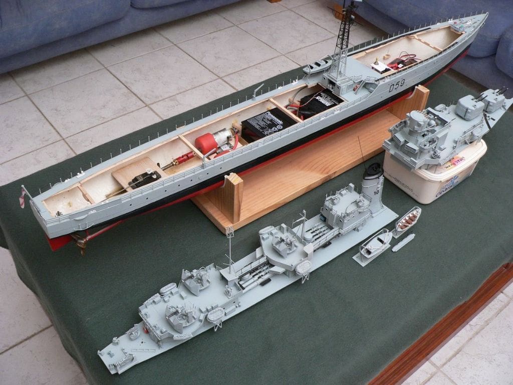
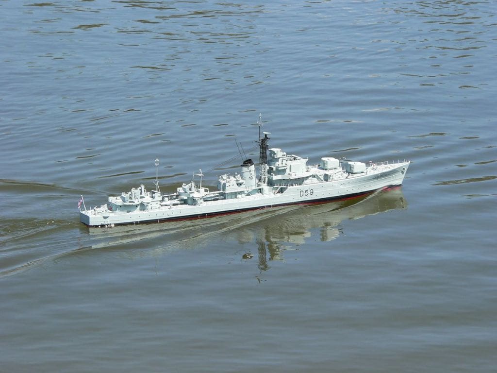
Two Robbe 6v electronic speed controllers each control a 950D 15v motor fitted with a 2.5:1 reduction gearbox and radio control is by a four channel system. The model moved reasonably well in the limited space of the swimming pool and sat on the water line. So far so good, although I did have to remove some lead later once the model was complete.
Superstructure
Next task was to start construction of the upper works. As I was converting this model from a British Battle class destroyer to HMAS Anzac, I had to scratch build most of the upper deck structures as they are differently shaped. I had done as much research on the internet and from books as I could and I was able to acquire a set of model makers’ drawings on CD from the Australian Navy Historical Society. These proved invaluable, especially when I printed them on my home computer at 1/96 scale.
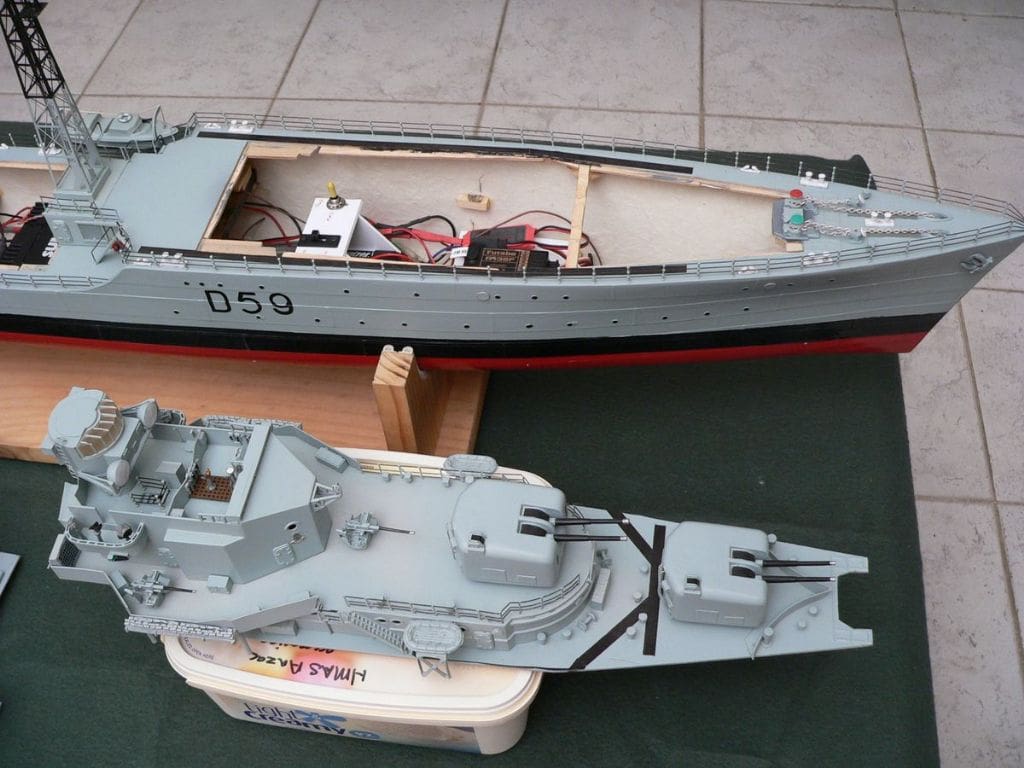
In order to complete the transformation I had to source some Mark VI gun turrets from a supplier in Queensland. I also needed an extra STAAG mounting (Stabilised Tachographic Anti-Aircraft Guns) as the kit only came with two and HMAS Anzac had three and lastly, a triple barrel squid mortar for the quarterdeck.
Using the printed copy of the plan I had received on CD as a template for the superstructure, I was able to utilise most of the original printed styrene card pieces provided for HMS Solebay, only making changes where required.
For example, the forward end of B Deck is curved with short angled bulkheads at each end. I cut out and secured the small angled bulkheads first and then cut a strip of plastic card to the correct width (the height of the bulkhead) and using a combination of rolling and mild heat managed to bend it to the correct curve. It was then a simple matter to trim it to the correct length and glue it in place with some bracing pieces on the inside. Once the glue had set I was able to trim off the excess deck. The bridge structure was wider at the forward end and was also higher, but this did not present too many problems. Paper templates for any sections that had difficult angles or curves made the task easier. The Q gun deck was a double level structure on HMS Anzac so I had to scratch build the top section complete with walkways and ladders and the lower half also required some changes. The amidships and X gun deck houses required varying levels of scratch building.
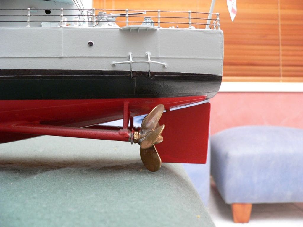
With most of the superstructure complete, secured to the deck by screws from underneath and sprayed with an undercoat of grey, it was time to venture down to my local lake for some more serious trials. The model moved okay, but the speed and manoeuvrability were not what I was expecting. I concluded the white metal propellers and rudder were inadequate for the job, so I fitted two 40mm diameter four bladed brass propellers and fitted a new rudder from styrene card and brass tube. The consequent improvement in speed was apparent and closer to what I considered to be a scale maximum speed and the manoeuvrability was also greatly improved, although steering astern was still not as good as I wanted. I added an extension to the bottom of the rudder and this made a significant difference, but I still felt it needed something more. So, I made another rudder with the same size blade, but moved the rudder post forward approx 5mm, which improved the astern handling.
With the superstructure completed I began to think about how much extra detail I could add. It was then I realised I had an almost endless supply of ideas sitting in Sydney Harbour. Tied up to the Sydney Maritime Museum’s wharf is HMAS Vampire, a Daring Class destroyer that is open to the public. The Daring’s were a descendant of the Battle Class so there are a lot of similarities. A couple of visits and many photos later I had a good idea of what I wanted to achieve.
Detail work
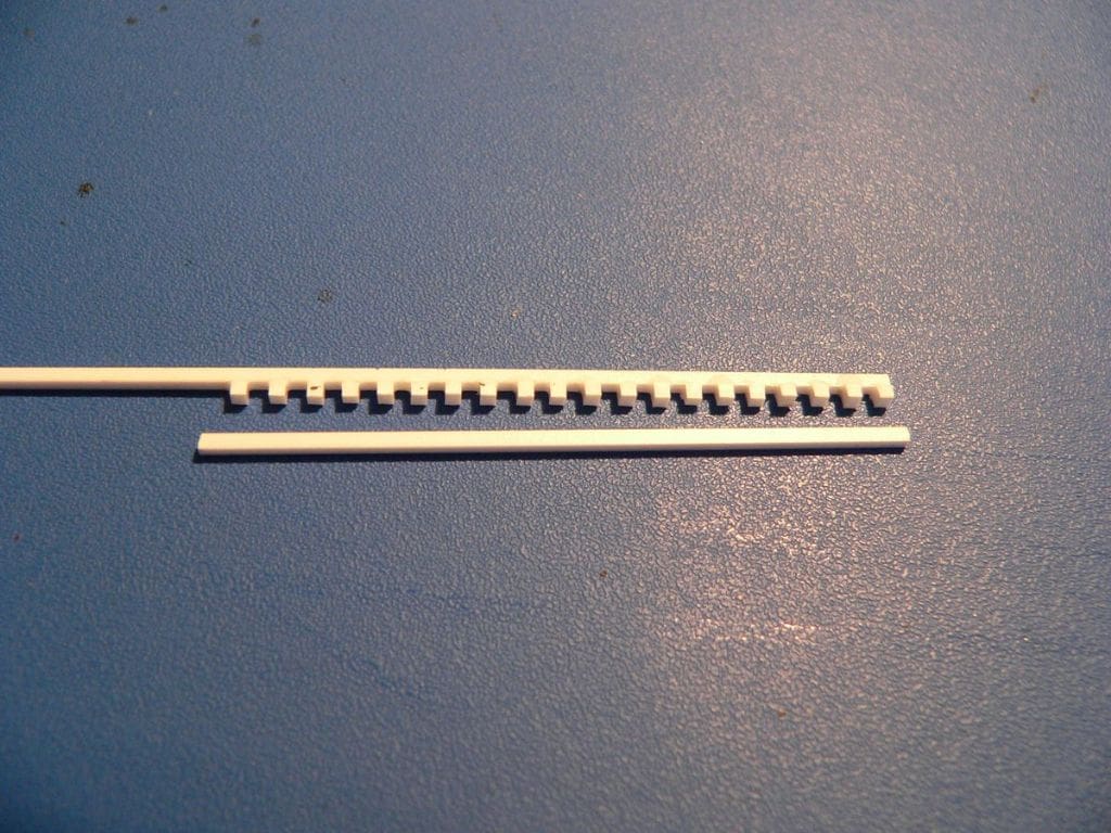
Starting on the forecastle, I wanted to simulate steel strips welded to the deck. I marked out where I wanted to place the strips using a pencil then cut fine plastic strips to length and superglued them in place. When it was painted it looked quite good. I also needed a lot more mushroom vents than were supplied with the original kit and I wanted to add more detail to the bridge in the form of voice pipes, phones and a wooden grating on the deck. So with some ingenuity, a sharp knife, some styrene card and liquid latex I was able to make moulds for a number of small items. I could now produce as many phones, vents, upper deck lights and watertight doors as I wanted. The resin, which I got from a craft shop near home had no odour whatsoever.
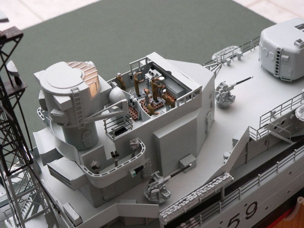
To make the wooden gratings I laid a length of 1mm square plastic strip on my small portable flat glass work top. Short sections were cut from another piece of 1mm square strip and glued at right angles across the long strip at 1mm spacing to the length required and then another long strip was glued to the small pieces parallel with the first long strip. This was repeated until I had a section that was big enough and when painted brown looked reasonable. This was installed on the bridge deck with telephone hand sets and voice tubes. The tubes were made from copper wire stripped from co-axial cable, bent and filed to shape. Cables attached to bulkheads were made from fine brass wire, bent to shape and stuck on with superglue. The radio direction finder attached to the front of the bridge was entirely scratch built from plastic strip and brass wire. The bridge details were gleaned from photos of a mock up Battle Class bridge on the CD from the National Archives.
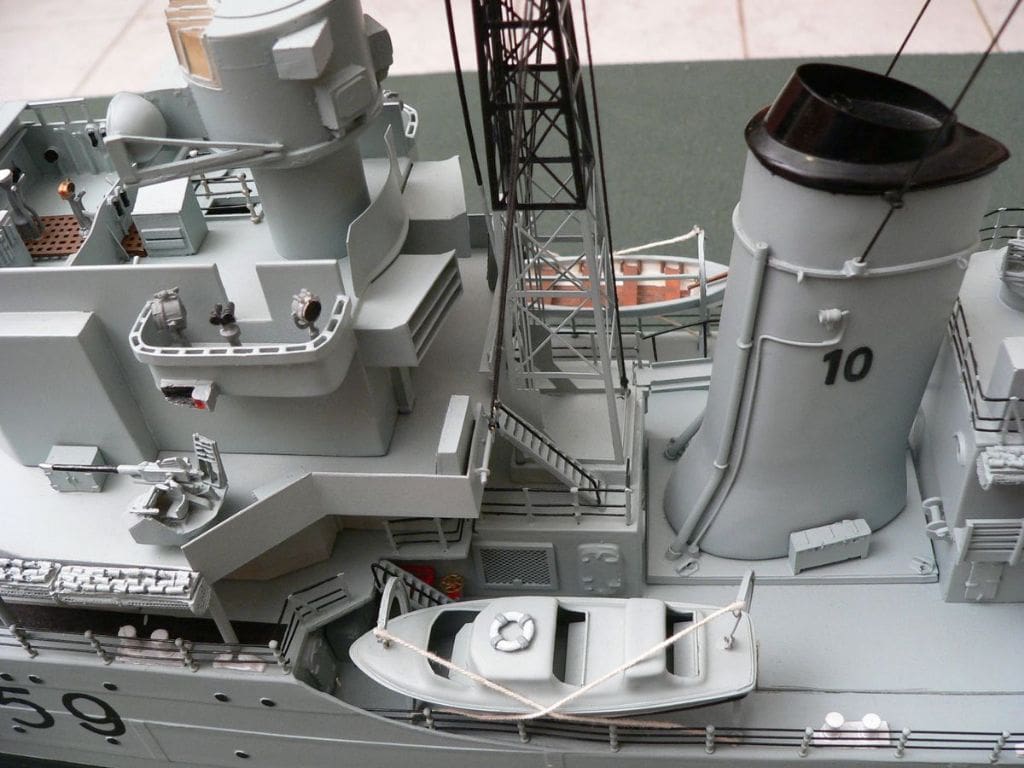
The etched brass mast supplied by Deans Marine went together quite well. A simple jig of a piece of a 25mm square timber screwed to a flat piece of board enabled two sections to be soldered at right angles to one another by laying the first up against the block. The cross pieces were made from a strip of flat brass and brass wire together with some brass tube for the mast truck. The antenna on top was made from flat plastic strip cut to size, laid out on the glass worktop and then glued together.
Type 294 Radar
This was motorised using a zoom motor from an old video camera. It was already fitted with a reduction gearbox and using a 3.5v battery the rotation speed is perfect. The motor is inside the galley under the mast with a piece of 1mm round plastic as a flexible coupling. Some silicone grease provides lubrication to the round strip where it touches the mast. An alternative would be to use a micro servo motor.
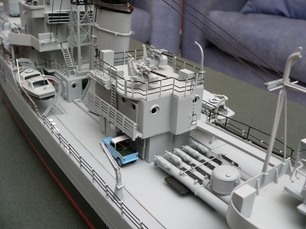
Torpedo tubes and turrets
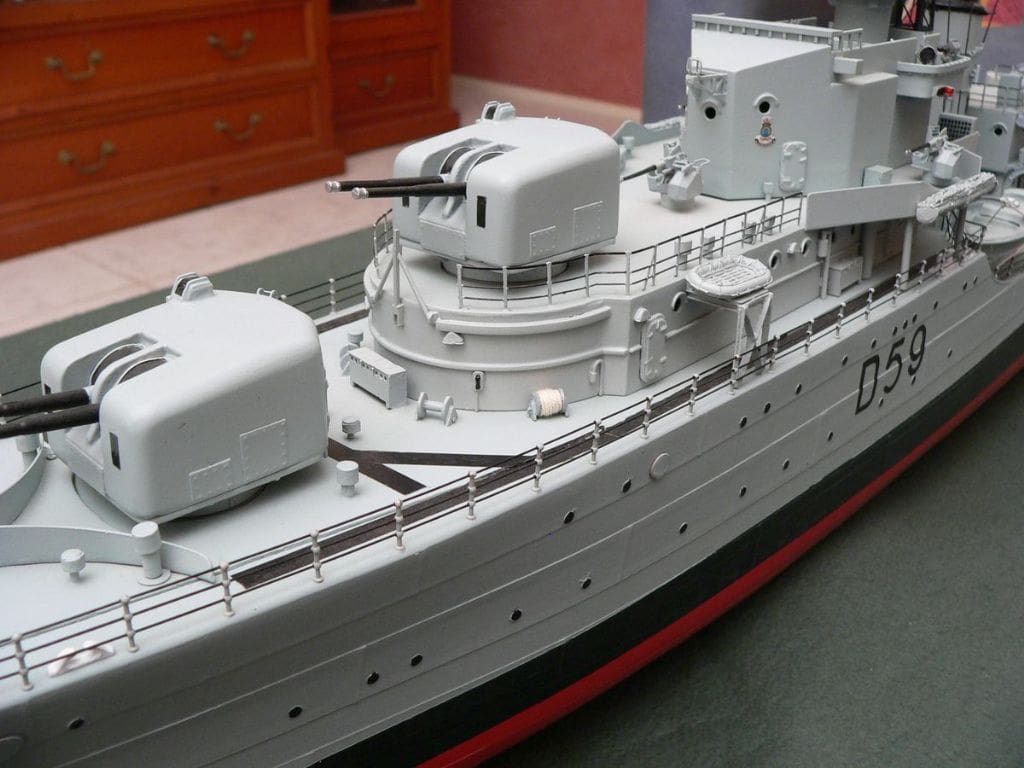
The tubes are supplied as solid resin castings but I decided to scratchbuild my own. Plastic tube was used for these, cut and sanded to the required shape, glued to the supplied base and utilising the original Deans Marine white metal fittings. The torpedoes are from black 4mm plastic knitting needles. Both ships were fitted with two Mark VI turrets each with two 4.5 inch guns. A local manufacturer in Queensland was able to provide me with the two turrets, the quality of which was excellent and assembly simple. Some plates with simulated rivets were added to the exterior as per the reference photos.
The third STAAG and Bofors mountings
After building the two STAAG weapons that came with the kit I decided I would try my hand at making the third from scratch. The splinter shield and base I could make from styrene card but the main body of the mounting was going to be a problem. I solved this by making a one off mould from one of those supplied using liquid latex. I successfully cast the piece I needed in resin although the mould itself did not survive. There wasn’t too much of a description of the construction of the Bofors mountings. So back to the internet for more information and after that, construction was relatively easy.
Other fittings
The fire hydrant points were made using 2mm plastic tube and some small hand wheels I obtained from the local model railway shop. 2mm wide flat plastic strip was used to make the metal fire hose holders. These were rather tricky being so small but a scrap piece of resin moulding from one of the STAAG mountings was the perfect size to use as a frame to support the plastic card strip until the glue dried. Once the glue was dry the fire hose holder was easily removed from the former, painted and stuck to the bulkhead next to a hydrant point. The triangular shaped upper deck lights were cast in resin and stuck wherever looked appropriate.
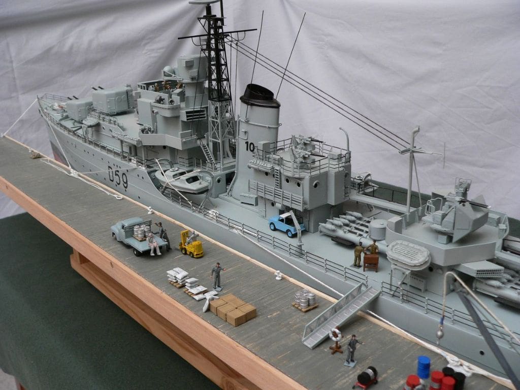
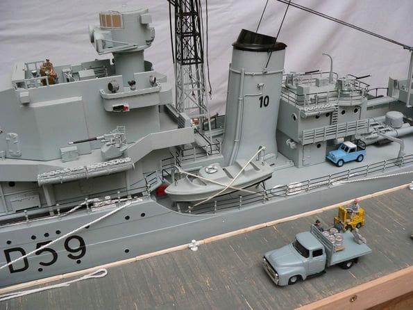
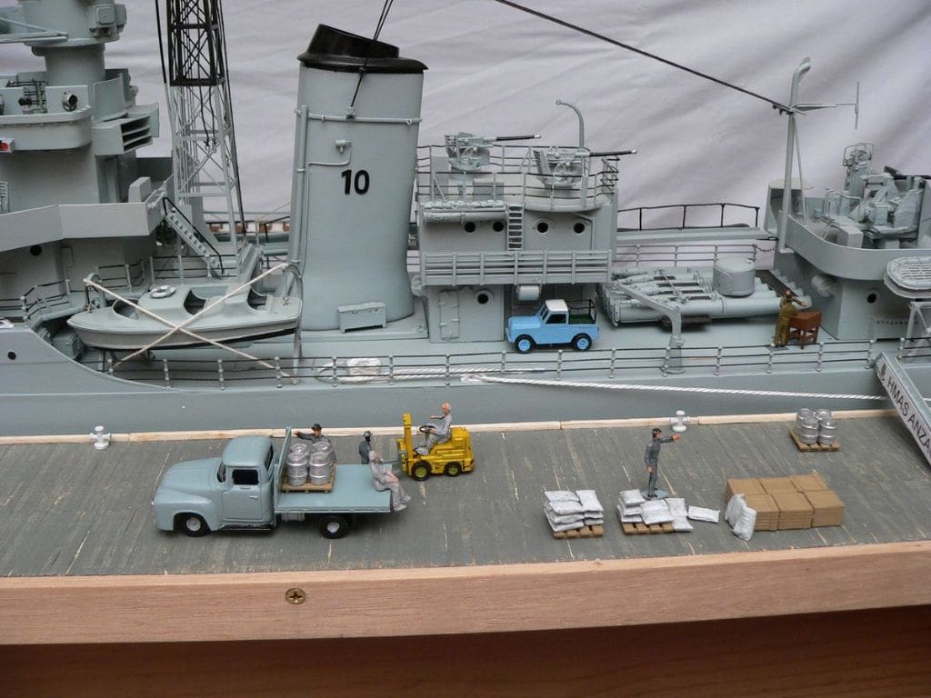
On the internet I discovered three photos of HMAS Tobruk taken in 1952. The photos were taken from an American destroyer while she was steaming alongside. The thing that stood out the most was a Series One short wheelbase Land Rover secured to the deck on the port side adjacent to the Q gun deckhouse. The picture clearly showed a sailor working on the motor with the bonnet open and leaning back against the windscreen. There is another crewman sitting on a towel on the back while a mate is leaning against the rear guard talking to him. This was a detail that had to be added, but nowhere could a 1:96 Land Rover be located.. The only solution was to make one, so back to the internet for research material. Trial and error by holding the drawings thus obtained against the side of the model resulted in the right size being determined. The wheels of a small toy Ferrari were a perfect match and the bucket seats although not quite true scale look better than nothing.
The ship’s boats were made up as per the kit drawings supplemented with those from the National Archive.
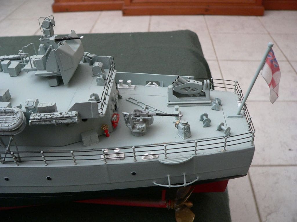
The triple barrel Squid mortar on the quarterdeck was made using templates from pictures found on the internet and on the CD. A small brake wheel from the model railway shop added detail.
The flag was made by sticking a small piece of fake (polyester) silk to a piece of paper with double sided tape and printing onto the silk the flag itself using an HP DeskJet colour printer. The ink shows through both sides and the edges were sealed with superglue before cutting. The flag staff is plastic tube with a slot in the end for the flag. The flag was shaped and then soaked in thin superglue to retain its shape.
Most of the supplied etched brass guardrails were replaced with 10mm three hole brass stanchions and fine plastic coated trace wire for the guardrails.
The crew are model railway HO scale. Yes, a bit oversize but not horribly so.
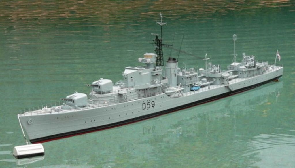
Painting
The hull was painted before attaching any of the superstructure. Red car touch up paint was used for the bottom and satin black for the boot topping. The main warship grey was actually Tamiya Light Blue (Luftwaffe). To simulate the portholes, a similar sized hole to those on the hull was cut in a thin piece of scrap plastic card then this was then held over the raised mouldings and the indentation filled using a permanent black marker pen.
Conclusion
Overall I was more than happy with the quality of the kit. A few more illustrations of the Bofors and STAAG mountings would have been helpful as I found the description in the instructions to be rather brief and difficult to follow. The conversion was certainly a challenge and there were times when I thought I had bitten off more than I could chew.
I have since changed the propellers yet again and fitted 45mm 5 blade brass propellers. They look oversize and incorrect out of the water, but I have finally achieved what I consider to be true scale speed. Unfortunately the ‘thrust cone’ from the propellers pushes the stern up and the bow down slightly, but HMAS Anzac still looks good on the water. In 2007 I joined the Hubertus MBC, Luddenham, website: http://sites.google.com/site/hubertusmbc/ who are closely associated with the Hubertus Country Club and use their lake and some of their other facilities south west of Sydney, New South Wales.
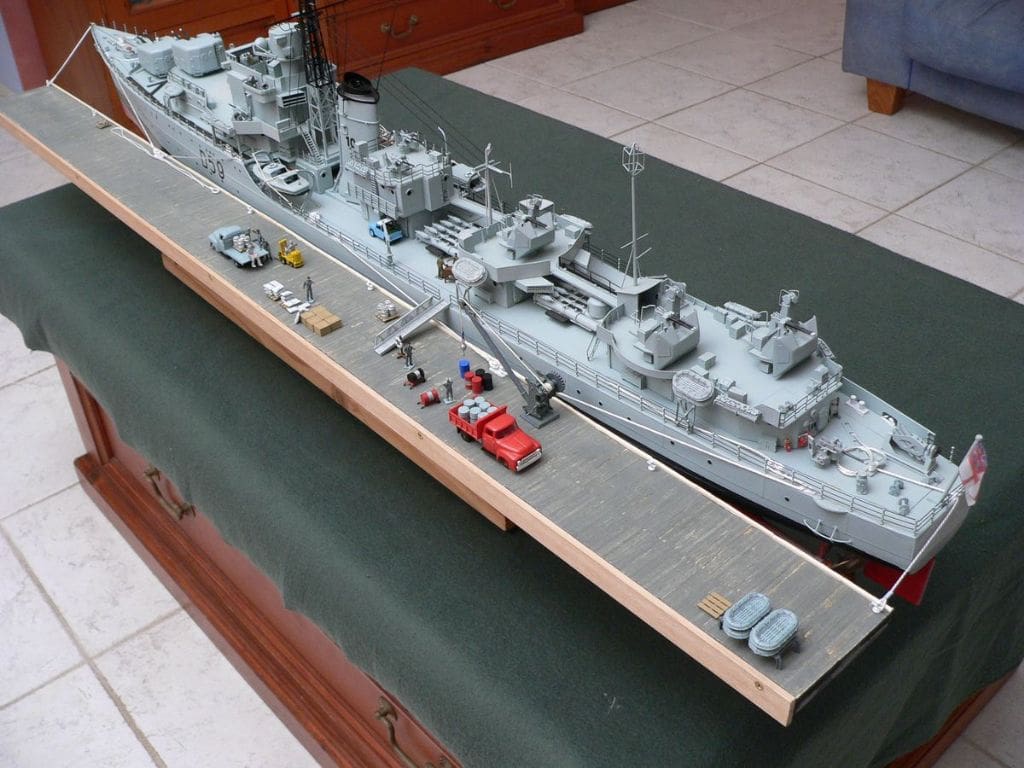
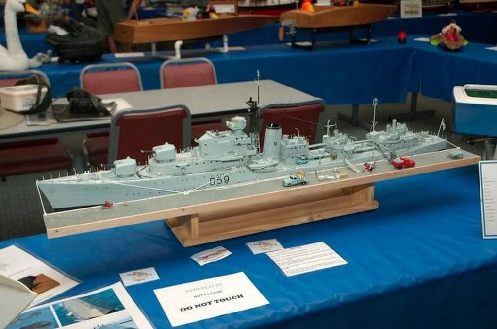
In 2008 our club hosted the Sydney Model Boat Show and just to be different HMAS Anzac was exhibited tied up alongside a wharf taking on stores.
Thanks to my wife for putting up with the use of the coffee table and now the dinning table with the next project, a replica of the stealth boat Sea Shadow designed by the Skunk Works in the USA. At over a metre long and half a metre wide it takes up quite a bit of space! I would welcome any comments about HMAS Anzac and can be contacted by email: [email protected]
References
Hobby shops
R2 Model Marine: Kit, propellers and stanchions. Web site: www.r2modelmarine.com
Casula Hobbies (model railways): Plastic card, crew, small brake wheels. Web site: www.casulahobbies.com.au
Kelletts Hobbies: Paint, styrene card and glue. Web site: www.kellettshobbies.com.au
Adhesives
Revell polystyrene glue for the styrene card
Aquader waterproof wood glue for the wood frame and deck.
Fibreglass resin to attach frame work to the hull, make repairs and secure and seal propeller shafts, A frames and rudder post.
Reference material
The Australian Naval Historical Society
The National Maritime Museum
The National Archives
The Australian Navy Heritage Society

