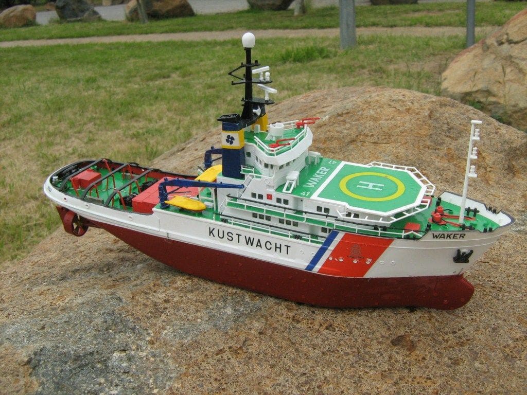
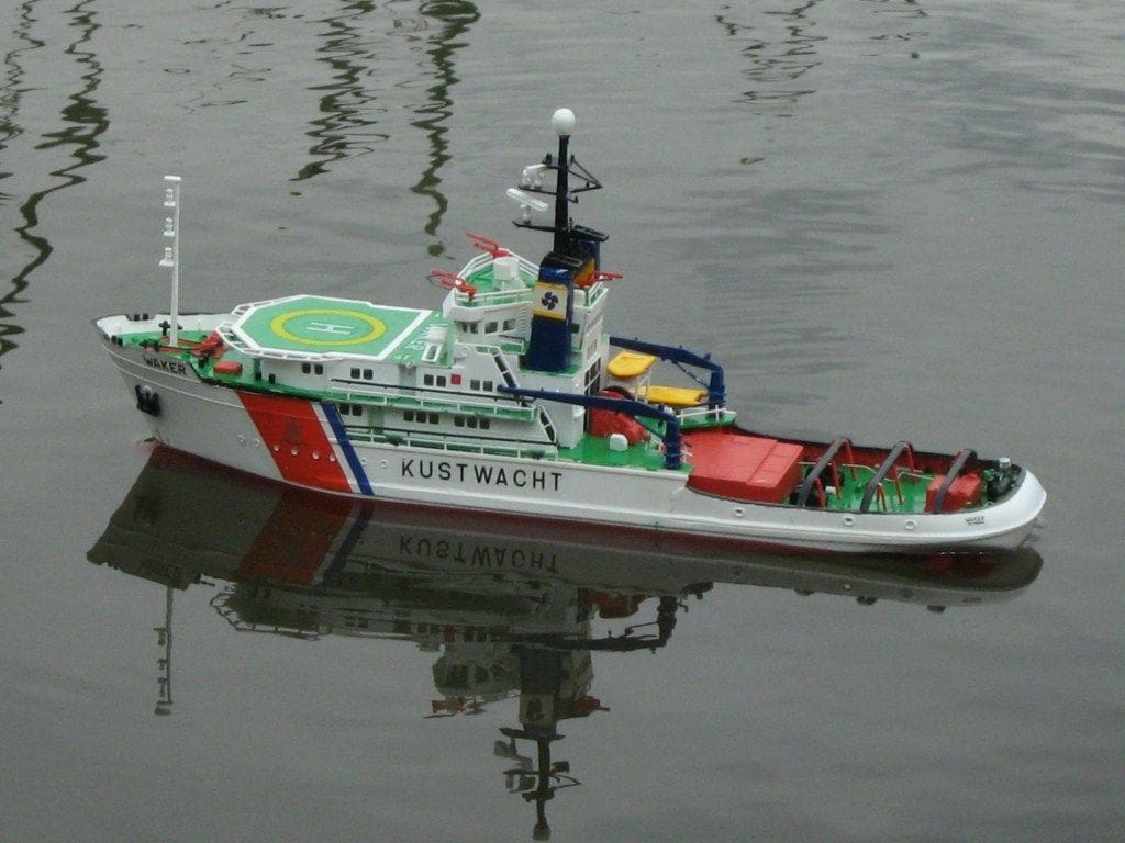
Eris Kennedy converted this Revell kit to radio control

My father used to say that the best type of boat for a working model is a tug and ETV Waker, despite being sold as a static model, does seem to support this theory. However, why would one build any working model tug or otherwise at this scale of 1/200?
Well, for me there are several reasons. First our club holds an annual event on an indoor swimming pool which lends itself to smaller models. So far I have built several models for these occasions and all are plastic kits converted to working models. Also, I find plastic kits to be economical, relatively quick to build and low impact in terms of the household. Being able to build inside the house is an advantage during winter. Finally I have found that powering these models by means of breaking down a servo to its constituent parts is cheap, effective and relatively straightforward.
Enjoy more Model Boats Magazine reading.
Click here to subscribe & save.
Of course not all plastic kits are suitable for this treatment. One has to be certain that the hull has sufficient draft and displacement to float on its correct waterline and be adequately stable as well. With a little experience you can judge what will probably work and what won’t.
I spied the ETV Waker in the shelf at a local hobby store and identified it as a suitable candidate for motorising and it had another attraction because unlike my previous undertakings, this model was twin screw. How intriguing I thought it would be, to build a diminutive model tug with full rudder control and independent propeller control.
The kit
The kit is generally of excellent quality. Parts are nicely made and fit well and the only issue was the plastic used. Though generally adequate it seemed to have a slightly soft and chalky quality about it that was not typical of the material normally encountered with injection moulded plastic kits. As a consequence, some breakages occurred whilst removing smaller pieces from the sprues, but otherwise this kit was pleasant to construct.
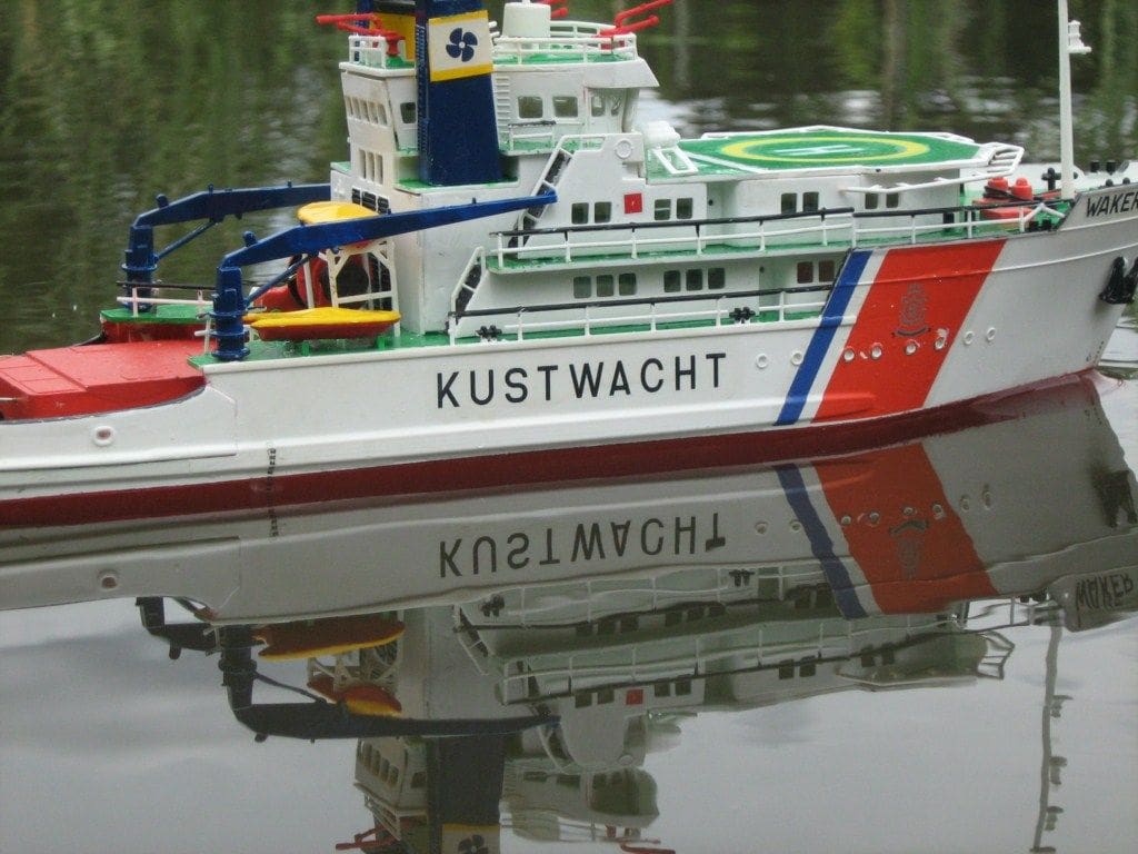
The set of decals is excellent and one particularly pleasing aspect was the propellers which are handed and thus can be installed as contra-rotating units. This is significant because to have both propellers turning in the same direction would offset the handling advantages offered by the twin prop installation, so: ‘Good one Revell’!
As this article concerns the creation of a working model I will not go into detail about kit construction. If you would like to attempt the conversion yourself here’s how to go about it.
Drive train
The initial task is to acquire some hardware for the working parts. The stern tubes are from stock brass tube of 1/8 inch diameter. The shafts are from a smaller diameter brass tube (or rod) that was selected because it telescoped nicely inside the tube stock. This same material is used to make up the rudder stocks and tubes.
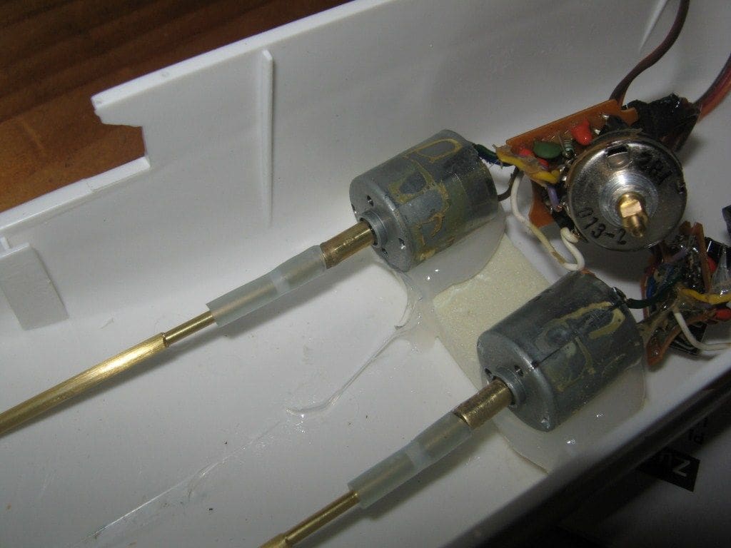
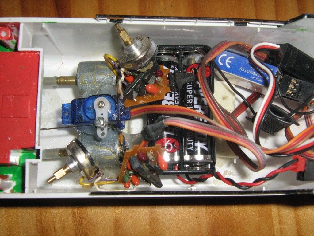
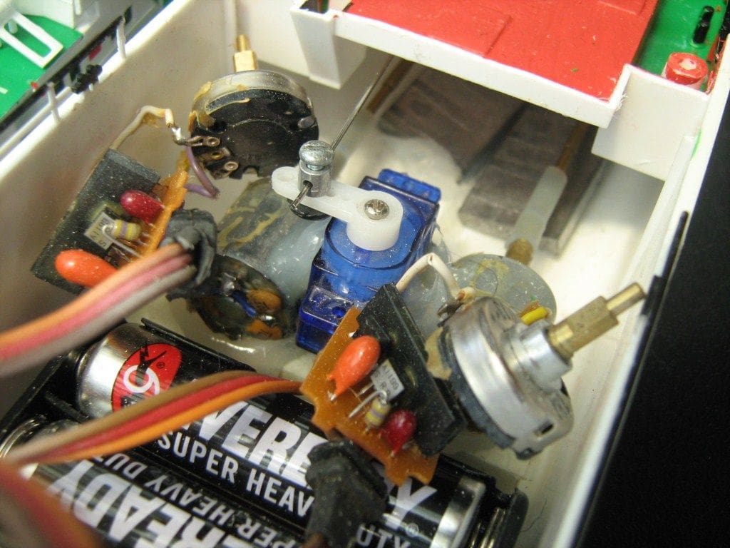
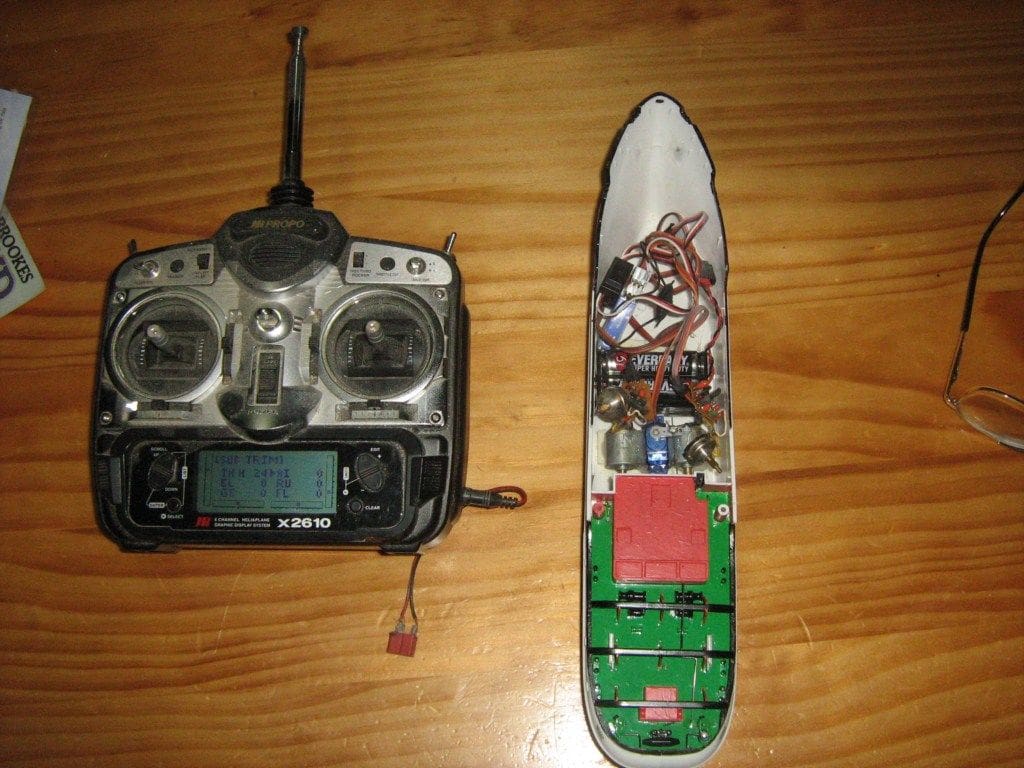
At this point you also need to create your power plants with their integrated speed controllers. Do this by acquiring two standard size model aircraft servos and judiciously chopping them open! The objective is to extract the motor, the IC circuit board and the potentiometer intact whilst ditching the remains of the case and the associated gears. This job can require some ingenuity and care and the exact procedure will depend on the brand of servo you use.
You will find that you can plug the servo into your receiver and get proportional power output as well as a neutral point and both forward and reverse thrust. Note that the neutral point for each motor can be set by adjusting the spindle on the potentiometer until the propeller comes to a stop.
You will need to extend the output shafts on the motors so they can take the silicone tube couplings. I did this by cutting three telescoping diameters of brass tube into lengths and gluing them together. By this means it is possible to epoxy the adapter to the pinion gear on the motor end while the diameter is reduced at the other end sufficiently to take the silicone tube coupling. Gluing these adapters nice and straight onto the pinion gears is very important though for obvious reasons.
The hull
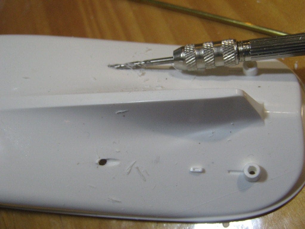
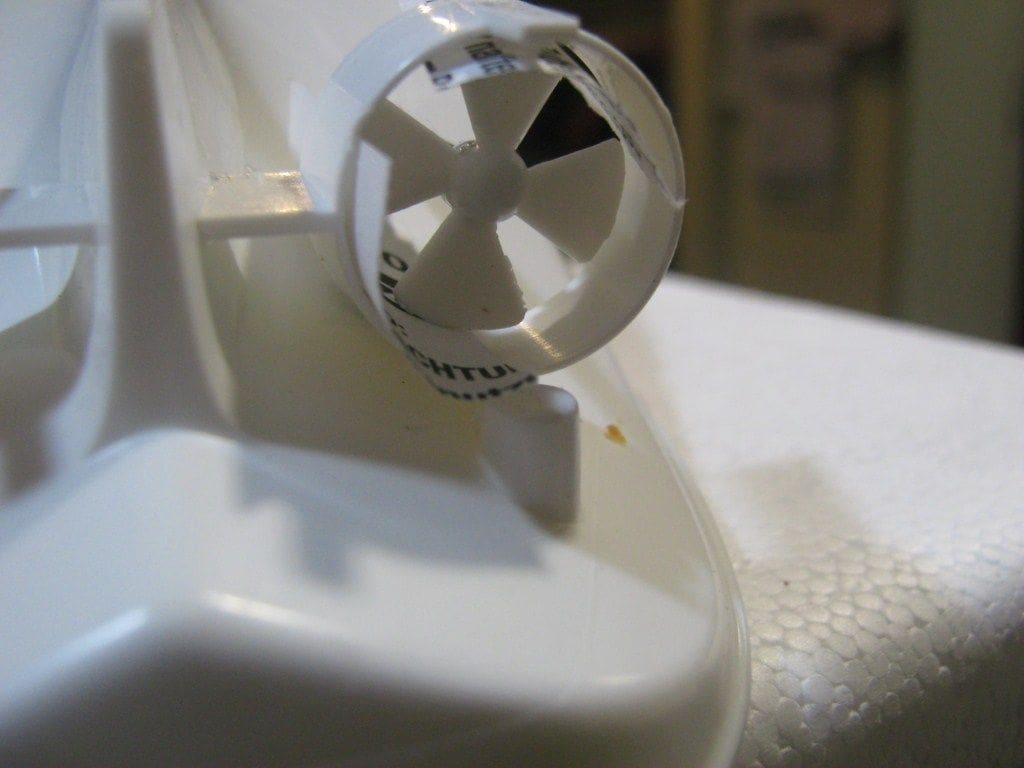
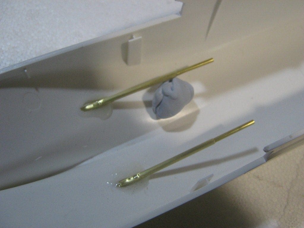
Next, we need to modify the one piece hull to convert it to a working model. Start by locating and drilling out slightly oversize, the holes for the stern tubes. Then drill out the propellers and glue them to the ends of the propshafts. The shafts can be left over long at this time. Now we install the fixed Kort nozzles and then, install without gluing, the stern tubes and the propshafts into the hull. Line up the propellers inside the Kort nozzles so there is adequate clearance and then put a blob of five minute epoxy on to the point where the stern tube exits the hull. With everything set up carefully, just leave this glue to set. It is a good idea to use paper rolled into a tube inside the nozzles to ensure proper clearance is maintained right round the props whilst the glue sets. The end result should be secure stern tubes aligned such that the propellers spin clear of the inner surfaces of the nozzles.
Motor installation
I won’t be prescriptive about shaft and tube lengths, but be mindful that the quarter deck will be glued in place. Should it be necessary to have any chance of replacing a coupling, the motors need to located no further aft than amidships.
The motors can be mounted by ‘floating’ them on blobs of silicone sealant, however because of the angle of the propshafts and the desire to have the motors well forward in the hull, there is a substantial gap underneath each motor. To close this gap, shape and glue inside the hull (with silicone) a piece of dense foam plastic packing at a location directly under the motors. Size the foam block so that there is 5mm to 8mm of space under each motor. Now you can put generous blobs of silicone on the foam packing at the points beneath the motors and install and align them to their respective shafts with the couplings. The couplings will keep the motors aligned while the silicone sets. Be careful with this task as a badly aligned motor is hard to fix later.
Note that it is possible to hold a motor with the coupling fitted, in approximately the correct position, with your fingers while inserting the shaft into the stern tube and the pushing it into the end of the coupling. Even though the coupling is pliable, silicone tube it is rigid enough in short lengths to allow this procedure to work.
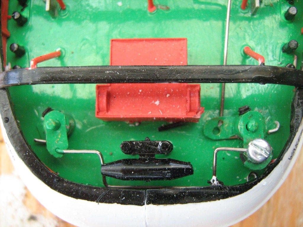
Rudders
I agonised over whether or not to conceal the rudder linkages below deck or run them above as I was concerned that visible linkages would detract from the aesthetics. However if I did conceal the mechanism and something went wrong there would be no way of accessing the tiller area without destroying the model. Pragmatism eventually won the day and I opted for the external option. As it happens, the wire linkage and tiller arms melt into the other deck clutter so that they are not really noticeable.
The after deck was installed first and then the holes for the rudder stocks were drilled from underneath prior to the rudder tubes being installable with epoxy and it was possible to use the kit supplied rudder blades. The plastic stocks were cut off and the rudders carefully drilled to take a thin brass tube stock instead. Experience has taught me that you must on any model boat be able to remove the rudders so that should the need arise you can withdraw the propshafts out of the model. Model aircraft wheel retaining collars prevent the rudders from dropping out of the model. These collars have grub screws that can be gently tightened on the rudder stocks.
Two tiller arms were soldered at right angles to the starboard rudder collar and just one onto the port collar. This enabled the wire rudder linkage to be brought aft from the servo to the lower arm on the starboard collar. The movement is then transmitted across to the port collar via a linking wire. Note that the linking wire needs to be shaped so that it can pass around the aft towing bitts.
The rudder micro-servo is located between the drive motors and is installed on its own blob of silicone.
Access
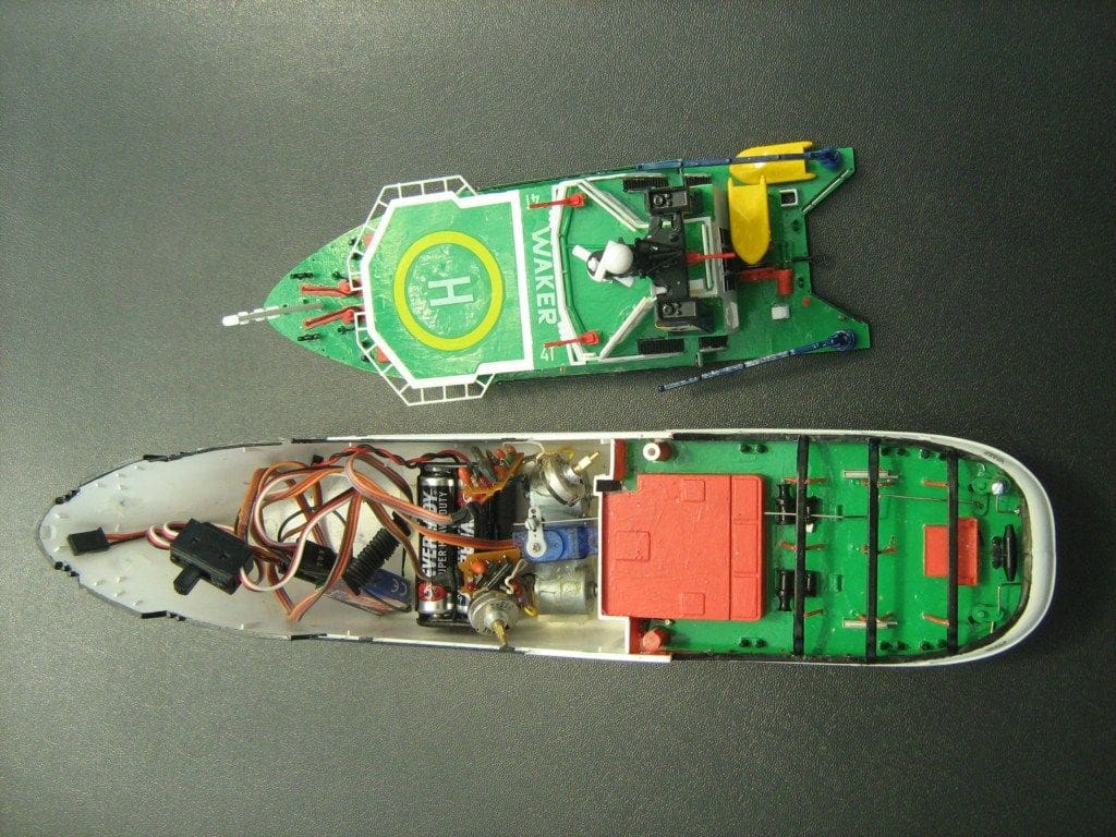
With this sort of project one of the most important questions is how will the interior of the hull be accessed? In the case of Waker I found that while the after deck needed to be glued in place, the forward deck section could be left unsecured such that it can be lifted of the model as required. Of course it is not watertight, but water should rarely get high enough for this to be an issue – hopefully!
Trimming
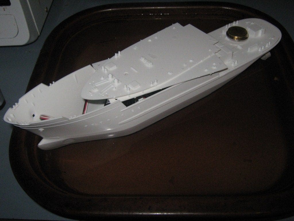
This is always a critical step with converted plastic kits. Some preliminary assessments prior to construction indicated that the model should float okay when finished but one can never be certain of the end result. As it so happened, it all worked out just fine.
The final trimming session was conducted in a tub when the model was complete. A few grammes of lead were required aft to get the model down to its marks and on an even keel and the best way to secure the ballast is once again with silicone sealant. With the superstructure in place the model seemed sufficiently stable though I resolved not to attempt towing operations because an inadvertent sideways pull could easily result in a capsize.
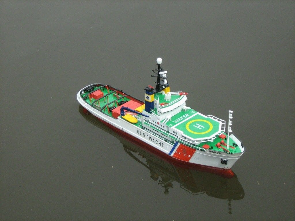
On the water
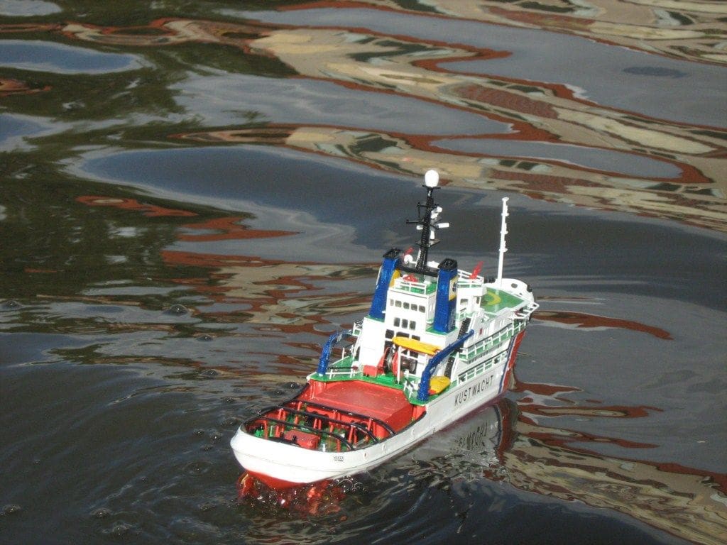
The ETV Waker has now had two sea trials, both of which have been very successful. Despite reservations about stability which arose during the initial trimming process I was pleasantly surprised. The model is tender, but only to an extent that is probably realistic.
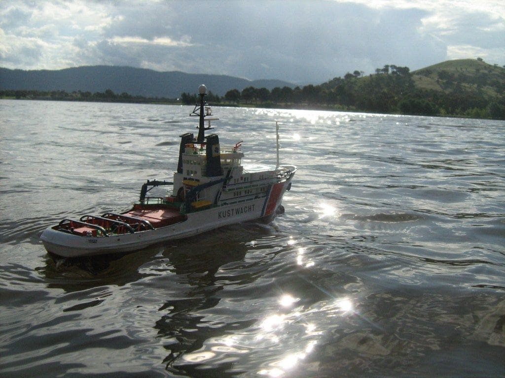
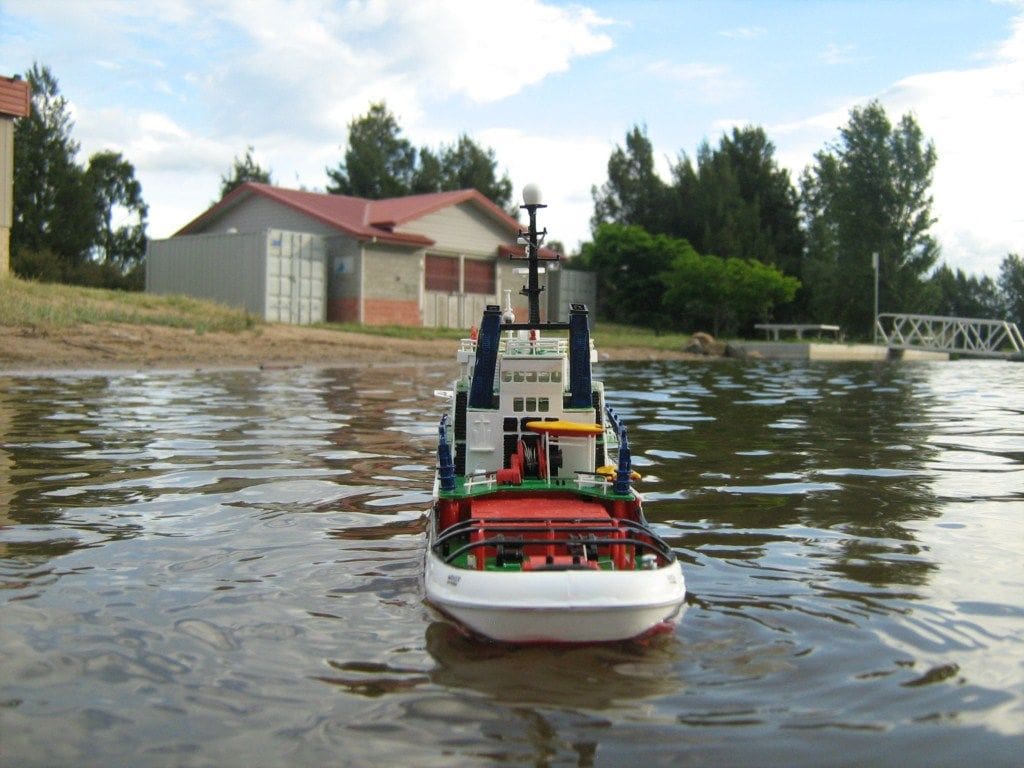
On the first trial the model was deployed on a local lake in a sheltered location when the water was dead flat with minimal wind effect. It was immediately apparent that the independently powered screws provided excellent manoeuvrability.
Steaming ahead was a little awkward because the left hand throttle stick, on the transmitter currently being used, has spring centre loading and the other does not. I thought of disconnecting the spring, however previous experience has taught me that this can involve major surgery. After a little practice, the best technique was to advance the right hand stick, i.e. the one without spring loading and then bring the other stick up until the model was steering a straight course. Perhaps in time I’ll set up a more appropriate system. but for the time being it’s okay.
The rudder response is quite good, although it is largely incidental given that one can both manoeuvre and hold a heading with the motors, but top speed was not as expected. I had thought the motors would, if anything, be too powerful for the model. However they have proved to be just about adequate and possibly slightly insufficient to allow the model to achieve the speed that permits a scale wave form. This could be caused by inadequate voltage to the motors or it may be the standard kit scale plastic propellers. However, the model moves along at close to walking pace which is adequate for our purposes.
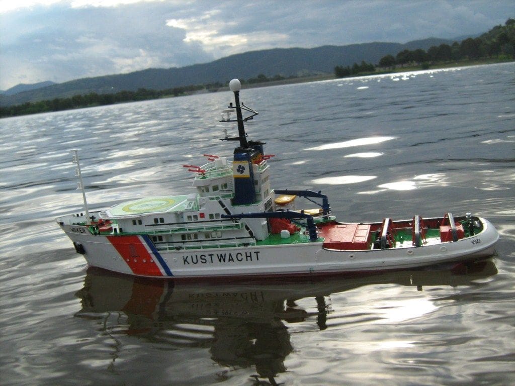
On the second sea trial some days later, the tug was sailed on the main lake. The wind was towards the shore at 10 to 15 km/hr and the wavelets were perhaps 4 to 6 centimetres high, but not breaking. ETV Waker handled these conditions with aplomb and even lying at right angles to the direction of the wind and waves the model demonstrated a safe amount of reserve buoyancy and stability. My heart missed a beat a couple of time when a gust of wind caused her to heel over, but she recovered and I suspect the real ship would heel in a wind of the same scale magnitude.
Conclusion
ETV Waker was built as a swimming pool model. After an enjoyable build I have a model that is quite versatile in terms of different sailing conditions and fun to handle due to the independent motor control, plus it looks good too! Perhaps a scratch built version, but a bit larger, would be a nice future project.
Happy sailing!
Revell ETV Waker Netherlands Coast Guard Tug
Model details
This is a 1:200 scale plastic kit supplied with a one piece hull and 140 parts in total. It makes up into a model that is 338mm long with a height of 162mm. A full set of Netherlands Coastguard decals is included and the UK retail price varies between £14 and £20 as of February 2011.
Ship’s history
She was built in 1976 as Smit Houston, but by 1995 she had been renamed Waker. She was still stationed in 2010 at Den Helder as part of the Dutch Coastguard Service.
The ship, chartered by Svitzer, has a length of 67.50m with a draught of 6.23m. She is driven by two six cylinder Stork Werkspoor diesel engines with a capacity of 2 x 4.600 HP (2 x 3.380 kW) and has an operational maximum speed of 14 knots

